EP0816036A2 - Procédé et appareil pour ramollir et écraser les bouteilles en matériau thermoplastique - Google Patents
Procédé et appareil pour ramollir et écraser les bouteilles en matériau thermoplastique Download PDFInfo
- Publication number
- EP0816036A2 EP0816036A2 EP97810405A EP97810405A EP0816036A2 EP 0816036 A2 EP0816036 A2 EP 0816036A2 EP 97810405 A EP97810405 A EP 97810405A EP 97810405 A EP97810405 A EP 97810405A EP 0816036 A2 EP0816036 A2 EP 0816036A2
- Authority
- EP
- European Patent Office
- Prior art keywords
- bottle
- neck
- tube
- deflector
- hot air
- Prior art date
- Legal status (The legal status is an assumption and is not a legal conclusion. Google has not performed a legal analysis and makes no representation as to the accuracy of the status listed.)
- Granted
Links
Images

Classifications
-
- B—PERFORMING OPERATIONS; TRANSPORTING
- B29—WORKING OF PLASTICS; WORKING OF SUBSTANCES IN A PLASTIC STATE IN GENERAL
- B29B—PREPARATION OR PRETREATMENT OF THE MATERIAL TO BE SHAPED; MAKING GRANULES OR PREFORMS; RECOVERY OF PLASTICS OR OTHER CONSTITUENTS OF WASTE MATERIAL CONTAINING PLASTICS
- B29B17/00—Recovery of plastics or other constituents of waste material containing plastics
- B29B17/0026—Recovery of plastics or other constituents of waste material containing plastics by agglomeration or compacting
- B29B17/0047—Compacting complete waste articles
- B29B17/0052—Hollow articles, e.g. bottles
-
- B—PERFORMING OPERATIONS; TRANSPORTING
- B30—PRESSES
- B30B—PRESSES IN GENERAL
- B30B9/00—Presses specially adapted for particular purposes
- B30B9/32—Presses specially adapted for particular purposes for consolidating scrap metal or for compacting used cars
- B30B9/321—Presses specially adapted for particular purposes for consolidating scrap metal or for compacting used cars for consolidating empty containers, e.g. cans
- B30B9/325—Presses specially adapted for particular purposes for consolidating scrap metal or for compacting used cars for consolidating empty containers, e.g. cans between rotary pressing members, e.g. rollers, discs
-
- B—PERFORMING OPERATIONS; TRANSPORTING
- B29—WORKING OF PLASTICS; WORKING OF SUBSTANCES IN A PLASTIC STATE IN GENERAL
- B29B—PREPARATION OR PRETREATMENT OF THE MATERIAL TO BE SHAPED; MAKING GRANULES OR PREFORMS; RECOVERY OF PLASTICS OR OTHER CONSTITUENTS OF WASTE MATERIAL CONTAINING PLASTICS
- B29B17/00—Recovery of plastics or other constituents of waste material containing plastics
- B29B17/0026—Recovery of plastics or other constituents of waste material containing plastics by agglomeration or compacting
- B29B17/0047—Compacting complete waste articles
- B29B17/0052—Hollow articles, e.g. bottles
- B29B2017/0057—Externally powered deformation tools, e.g. tools being part of relatively big non domestic installations, powered by motors
-
- B—PERFORMING OPERATIONS; TRANSPORTING
- B29—WORKING OF PLASTICS; WORKING OF SUBSTANCES IN A PLASTIC STATE IN GENERAL
- B29B—PREPARATION OR PRETREATMENT OF THE MATERIAL TO BE SHAPED; MAKING GRANULES OR PREFORMS; RECOVERY OF PLASTICS OR OTHER CONSTITUENTS OF WASTE MATERIAL CONTAINING PLASTICS
- B29B17/00—Recovery of plastics or other constituents of waste material containing plastics
- B29B17/0026—Recovery of plastics or other constituents of waste material containing plastics by agglomeration or compacting
- B29B17/0047—Compacting complete waste articles
- B29B17/0052—Hollow articles, e.g. bottles
- B29B2017/0068—Softening the hollow articles by heat and causing permanent deformation
-
- Y—GENERAL TAGGING OF NEW TECHNOLOGICAL DEVELOPMENTS; GENERAL TAGGING OF CROSS-SECTIONAL TECHNOLOGIES SPANNING OVER SEVERAL SECTIONS OF THE IPC; TECHNICAL SUBJECTS COVERED BY FORMER USPC CROSS-REFERENCE ART COLLECTIONS [XRACs] AND DIGESTS
- Y02—TECHNOLOGIES OR APPLICATIONS FOR MITIGATION OR ADAPTATION AGAINST CLIMATE CHANGE
- Y02W—CLIMATE CHANGE MITIGATION TECHNOLOGIES RELATED TO WASTEWATER TREATMENT OR WASTE MANAGEMENT
- Y02W30/00—Technologies for solid waste management
- Y02W30/50—Reuse, recycling or recovery technologies
- Y02W30/62—Plastics recycling; Rubber recycling
Definitions
- patents such as patent F - 9206448 - Levasseur / describe processes and devices using hot water vapor which is injected by its neck in the interior volume of the bottle to soften it.
- the object of the present invention is firstly a method for distributing a high calorific energy modulated according to the thickness of each of the three parts of the bottle to soften, i.e. to supply at the same time a greater amount of energy in the thicker parts and less important in the fine parts, the aim being that all the parts of the bottle, body, base and neck reach the softening point relatively at the same time.
- This modulation of the energy distribution makes it possible to work with a gas flow whose temperature is much higher than the softening temperature bottle material, so very quickly.
- the other object of the invention is achieve the aforementioned goal with a minimum of energy loss, i.e. by ensuring that the majority of the energy distributed will be captured by the bottle and not by elements surrounding it.
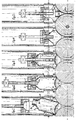
- Figures 1. to 5. show, very schematically, a possible variant of the process used.
- Fig. 1 The bottle 1. is first placed vertically, base down, on horseback between 2 rotary crushing drums 6. whose axes are horizontal and parallel. It is held in place by the lower part of the cylinder 12. or by any other appropriate means.
- the centering jaws 7. position the bottle 1. in the axis of the cylinder 12.
- the assembly consisting of the tube 2 for supplying hot air and the deflector 3. begins to descend.
- the deflector 3. is placed on the neck 1b. It thus ensures a additional centering of the bottle and exerts at the contact points 8. between the pellet there. and the rotary drums 6. a pressure helping to drive the bottle between the rotating drums.
- the flow of hot air emitted by tube 2. can be activated already before the deflector 3. lands on the neck as only a certain time is required for the heating element 10. for it to supply air to the desired temperature.
- Fig. 3. The tube 2. goes deep into the bottle and goes into the face position basically there. from the bottle.
- the flow of hot air which can reach several hundreds of degrees, is projected directly on the base la. from the bottle and this to relatively high speed.
- This flow velocity of the air flow slows down notably when it rises in the body of the bottle, given the large section available, to then accelerate notably in the constriction that constitutes the neck 1b ..
- the section available for the exhaust of the hot air is further reduced by the presence of the tube 2. which is there.
- the deflector 3. pressing on the neck at two points at the minimum, returns the hot air which escapes from the neck towards the external flanks thereof and along the neck 1c. of the bottle.
- the thickness of the walls of a plastic bottle is, in a relative way, inversely proportional to the distance of these walls from the axis of the bottle.
- the process subject of this invention puts the walls of the bottle in contact with a flow of hot air whose flow speed along these walls is itself relatively proportional to the different thicknesses thereof.
- the transfer of energy between the hot air flow and the walls of the bottle also being relatively proportional to the speed of this flow it follows that we transmit more of energy in the thick parts of the bottle and less in the thin parts. We can so use an air flow whose temperature greatly exceeds the temperature softening of the bottle material without running the risk of seeing the fine parts reach the melting point before the thick parts are softened.
- Fig. 5 When the whole part of the bottle below the neck is already crushed between the two rotary drums 6.and that only the neck 1b. and possibly part of the neck 1c.de the bottle is still above the crush point 6a. the hot air supply pipe 2. is outside the bottle and the hot air flow coming out of it is projected directly from the front on the neck 1b .. The deflector 3. is retained in advance so that it does not enter not in contact with the rotary drums 6.by stops not shown in the figure 5 ..
- the neck is usually the thickest part of a bottle is there even the part of the bottle that needs the most energy and time to get soften. It can be seen in FIGS. 4 and 5 that the process subject of the invention ensures at the neck 1b. of the bottle 1. the greatest distribution of energy and also the most long. It is indeed at the level of the neck 1b. that the air flow speed heat will be the highest and therefore also the energy transfer. It will be as at the level of the neck as the hot air, through the deflector 3. will act on the face inside and outside of the walls, thus doubling the contact surface with the hot fluid.
- the neck 1b. being crushed last by the rotating drums 6. will also be the part of the bottle that is the longest subjected to the hot gas flow.
- the hot gas flow being emitted by the mouth 2a. of the hose 2. inside and at the bottom of the bottle 1. it follows that all the thermal energy released cannot first be absorbed only by the bottle 1. itself, hence use optimal heat energy supplied.
- the tube 2. and the deflector 3. are already shown there in the "low” position, ie with the mouth 2a. of the tube 2. in close proximity to the base 1a. from bottle 1. so that the flow of hot air which escapes therefrom directly reaches this base. and the deflector 3. already resting on the neck 1b. from bottle 1.
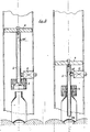
- Both Fig. 7. show, in two operating positions and schematically an alternative embodiment of the hot air flow supply tube characterized in that this tube is made of two elements sliding one inside the other telescopically.
- the fixed upper tube 2b. comprises the air flow heating element 10 .. In the variant described, it is secured to the cylinder 12. by means of the disc 22..
- the lower tube 2a. is axially movable and is integral, in this same variant, with the piston 4.
- This piston 4. can move in the cylinder 12. under the combined effect of the pressure of the air flow in the cavity 13. on the one hand and return springs 14. on the other hand.
- Each of these tubes can be made of suitable materials or combinations of materials suitable for their mechanical, insulating and non-stick qualities.
- the heating element 10. can, as a variant, be integrated inside the tube 2. or the tube 2a. or 2b.
- Fig. 9 schematically represents a variant where the heating element 10. is fixed and located between the piston 4. and the deflector 3. The air passes through this element of heating to be brought to working temperature.
- Tube 2. Presents, in its section located between the piston 4. and the deflector 3., one or more openings 2d. allowing, when the tube 2. is in position in the bottle, the admission of air hot supplied through the heating element 10. The passage of hot air from the heating element 10. to the tube 2. can be produced in different ways known per se.
- the deflector 3. can be designed as well as while resting on the neck 1b. of the bottle 1. in 20. and while centering the bottle to allow a correct insertion of tube 2. or 2a. it allows to divert the hot air flow leaving the bottle and directing it towards the outside flank of the neck 1b. and the along the neck of the bottle.
- the inner surface of the deflector can present, in this variant, several conical bridges 20. used for centering of the bottle, the space 21. between these bridges leaving a passage for the air flow coming out of the neck of the bottle.
- the surface of the deflector or its very material must advantageously have thermally insulating and non-stick qualities.
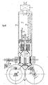
- Fig. 6. shows on the other hand, always as possible, various variants elements of which we indicate below possible modes of operation.
- One at least of the rotary drums 6. must be equipped with known training means. These can ensure a continuous or discontinuous rotation, at constant speed or at variable speeds.
- a version may provide a relationship between the speed of rotation of the rotary drums and the modification, during the crushing of the bottle, of the distance between the two rotary drums.
- One at least of the rotary drums 6. should advantageously be equipped to allow it to move parallel to its axis of rotation.
- a lever arm 15. centered at 16. can allow such displacement and also produce, by the weight of the assembly, the pressure necessary for crushing the bottle.
- Other means known per se, can be used to ensure the crushing of the bottle.
- a cam 17. mounted on the axis 18. of one of the rotary drums 6. can, in a possible variant, by a set of levers 19. shown very schematically in the Fig. 6., activate a centering mechanism acting on the centering jaws 7 ..
- This centering mechanism can be designed to accept different sizes and bottle shapes.
- the device which is the subject of the invention can also be produced in a version simplified or only some of the claims are applied.
Landscapes
- Engineering & Computer Science (AREA)
- Mechanical Engineering (AREA)
- Environmental & Geological Engineering (AREA)
- Processing And Handling Of Plastics And Other Materials For Molding In General (AREA)
Abstract
Description
Chacun de ces tubes peut être réalisé dans des matériaux adéquats ou des combinaisons de matériaux adéquats quant à leurs qualités mécaniques, isolantes et antiadhésives.
L'élément de chauffage 10. peut, comme variante, être intégré à l'intérieur du tube 2. ou du tube 2a. ou 2b.
L'un au moin des tambours rotatifs 6. devrait avantageusement être équippé pour lui permette de se déplacer parallèlement à son axe de rotation. Un bras de levier 15. centré en 16. peut permettre un tel déplacement et produire en plus, par le poid de l'ensemble, la pression nescessaire à l'écrasement de la bouteille. D'autres moyens, connus en soit, peuvent être utilisés pour assurer l'écrasement de la bouteille.
- Dispositif empêchant d'introduire des bouteilles mal orientées, encore bouchées ou contenant encore le contenu.
- Dispositif permettant d'accumuler une pluralité de bouteilles que la machine traitera une à une automatiquement.
- Dispositif triant les bouteilles selon les matériaux qui les constituent et /ou rêglant les paramètres de fonctionnement de la machine en fonction de ces matériaux.
- Dispositif distribuant à l'utilisateur un remboursement ou un bonus, sous quelque forme que ce soit, en contrepartie des bouteilles remises.
- Dispositif permettant une visualisation, par l'utilisateur, de certains des processus effectués par la machine.
Claims (13)
- Procédé pour réduire, par ramollissement thermique et écrasement mécanique, le volume occupé par une bouteille, vide, en matériau thermoplastique, caractérisé en ceci qu'un rapide flux d'air chaud est projeté directement contre la face intérieure du culot (la) de la bouteille (1), que ce flux d'air chaud est introduit dans la bouteille (1), au travers de son goulot (1b), par un tube (2) partiellement et profondément positionné dans la bouteille (1), que l'embouchure (2a) du tube (2), d'ou le flux d'air est éjecté, est positionné de préférence entre 4 et 20 mm., au maximum 50 mm. de distance de la face interne du culot (1a) de la bouteille (1), que la température du flux d'air chaud au sortir de l'embouchure (2a) du tube (2) est égale ou supérieure à la température de fusion du matériau thermoplastique, et que le flux d'air chaud ainsi introduit dans la bouteille (1) s'échappe de celle-ci par son goulot (1b) en utilisant l'espace laissé libre entre le flanc intérieur du goulot (1b) et la surface extérieure du tube (2) qui s'y trouve introduit.
- Procédé selon la revendication 1. caractérisé en ce que le flux d'air chaud qui s'échappe du goulot (1b) de la bouteille (1) par l'espace laissé libre entre le flanc intérieur du goulot (1b) et la surface extérieure du tube (2) est repris par un déflecteur (3) qui l'oriente de manière à ce qu'il s'écoule le long du flanc extérieur du goulot (1b) et du col (1c) de la bouteille.
- Procédé selon les revendications 1. et 2. caractérisé en ceci qu'alors que la bouteille (1) est progressivement écrasée, par son culot (1a) dabord, entre deux tambours rotatifs (6), le déflecteur (3) suit la bouteille (1) sur le parcours disponible.
- Procédé selon les revendications 1. à 3. caractérisé en ce que, alors que seul une partie du col (1c) de la bouteille (1) et le goulot (1b) de celle-ci n'ont pas encore été écrasé entre les deux tambours rotatifs (6), le flux d'air chaud sortant de l'embouchure (2a) du tube (2) est projeté frontalement contre le goulot (1b) de la bouteille (1), le tube (2) et son embouchure (2a) se trouvant alors hors de la cavité de la bouteille (1).
- Procédé selon les revendications 1. à 4. caractérisé en ce que le flux d'air chaud peut être interrompu à un moment déterminé au cours ou après l'écrasement de chaque bouteille.
- Appareil pour la mise en oeuvre du procédé selon les revendications 1. à 5. caractérisé en ce que le mouvement positionnant le tube (2) dans la bouteille (1) peut avoir pour élément moteur la pression qu'exerce, dans un cylindre (12), le flux d'air lui-même, non encore chauffé, sur un piston (4) solidaire du tube (2), la remise en position initiale du tube (2) étant assurée par des ressorts (14) ou tout autre moyen connu en soit.
- Appareil selon la revendication 6. caractérisé en ce que le déflecteur (3) est lié au piston (4) par un système de tringles et de butées.
- Appareil selon les revendications 6. à 7. caractérisé en ce que le déflecteur (3), dont l'axe coincide avec l'axe de la bouteille (1) et qui est mobile le long de cet axe, peut se poser en appui sur le goulot (1b) de la bouteille (1) pour en assurer le centrage par des moyens connus en soi et ce aussi pendant le déplacement axial de la bouteille (1) lorsque le fond (1a) de celle-ci puis le corps lui-même de la bouteille (1) est progressivement écrasé entre les deux tambours rotatifs (6), hormis évidemment dans la dernière portion de cette opération d'écrasement, des butées (9) empêchant alors que l'avance du déflecteur (3) ne le mette en contact avec les tambours rotatifs (6).
- Appareil selon les revendications 6. à 8. caractérisé en ce que le déflecteur (3), par la pression qu'il exerce axialement sur le col (1b) de la bouteille (1). permet aux deux tambours rotatifs (6) , contre lesquels le fond (1a) de la bouteille (1) repose aux points de contact (8), de mieux entrainer la bouteille pour son écrasement.
- Appareil selon les revendications 6. à 9. caractérisé en ce que la surface des tambours rotatifs (6) peut être molletée ou posséder un relief ou être equipée de pointes escamotables ou non, ou encore posséder un revêtement assurant une meilleure adhérence avec toutes les surfaces extérieures de la bouteille lors de l'entrainement et l'écrasement de celle-ci.
- Appareil selon les revendications 6. à 10. caractérisé en ce que les deux tambours rotatifs (6), dont l'un au moin est entrainé en rotation par des moyens connus en soi, sont pressés l'un contre l'autre par des moyens connus en soi et que l'un au moin des tambours rotatifs peut être déplaçé perpandiculairement à son axe de rotation de manière à permettre une variation de l'entraxe des deux tambours.
- Appareil selon les revendications 6. à 11, caractérisé en ce que le mouvement de rotation des tambours rotatifs (6) peut être continu ou discontinu et que la vitesse de rotation de ces tambours rotatifs peut, si nescessaire, être variée au cours du cycle, par example en fonction de la variation de leur entraxe.
- Appareil selon les revendications 6. à 12. caractérisé en ce que certaines des opérations réalisées par l'appareil sont volontairement rendues visibles à l'utilisateur.
Applications Claiming Priority (3)
| Application Number | Priority Date | Filing Date | Title |
|---|---|---|---|
| CH1573/96 | 1996-06-25 | ||
| CH157396 | 1996-06-25 | ||
| CH01573/96A CH693090A5 (fr) | 1996-06-25 | 1996-06-25 | Procédé et appareil pour ramollir et écraser les bouteilles en matériau thermoplastique. |
Publications (3)
| Publication Number | Publication Date |
|---|---|
| EP0816036A2 true EP0816036A2 (fr) | 1998-01-07 |
| EP0816036A3 EP0816036A3 (fr) | 1998-05-13 |
| EP0816036B1 EP0816036B1 (fr) | 2001-08-29 |
Family
ID=4213589
Family Applications (1)
| Application Number | Title | Priority Date | Filing Date |
|---|---|---|---|
| EP19970810405 Expired - Lifetime EP0816036B1 (fr) | 1996-06-25 | 1997-06-25 | Procédé et appareil pour ramollir et écraser les bouteilles en matériau thermoplastique |
Country Status (3)
| Country | Link |
|---|---|
| EP (1) | EP0816036B1 (fr) |
| CH (1) | CH693090A5 (fr) |
| DE (1) | DE69706375T2 (fr) |
Cited By (2)
| Publication number | Priority date | Publication date | Assignee | Title |
|---|---|---|---|---|
| EP1561558A3 (fr) * | 2004-02-03 | 2005-11-16 | GRUSAN di SANDRIN Giannino & C. s.a.s. | Dispositif de compactage de récipients en matière plastique |
| EP2119546A1 (fr) * | 2008-05-16 | 2009-11-18 | Dalla Valeria Giampaolo | Appareil de compactage thermo-électromécanique pour utilisation domestique et communautaire, pour une bouteille en plastique placée verticalement et procédé de compactage de la bouteille disposée verticalement |
Families Citing this family (1)
| Publication number | Priority date | Publication date | Assignee | Title |
|---|---|---|---|---|
| DE10121599A1 (de) * | 2001-05-03 | 2003-02-13 | Kortenbach Gmbh | Beheizbare Presse zur Reduzierung von Plastikflaschen auf abfallgerechte Restvolumina |
Family Cites Families (4)
| Publication number | Priority date | Publication date | Assignee | Title |
|---|---|---|---|---|
| FR2231497A1 (en) * | 1973-06-04 | 1974-12-27 | Leonetout Gabriel | Plastic bottle disposal - using hot air to soften plastic before crumpling by hand |
| FR2687085B1 (fr) * | 1992-02-10 | 1994-08-05 | Levavasseur Jean | Procede de recuperation selective de contenants vides et ensemble d'equipements pour sa mise en óoeuvre. |
| FR2691648B1 (fr) * | 1992-05-26 | 1995-09-08 | Levavasseur Jean | Procede et appareil pour la reduction de volume de contenants en matiere plastique. |
| FR2712529B1 (fr) * | 1993-11-15 | 1996-01-19 | Lamy Perret Emile | Dispositif de compression des emballages vides en matière plastique. |
-
1996
- 1996-06-25 CH CH01573/96A patent/CH693090A5/fr not_active IP Right Cessation
-
1997
- 1997-06-25 EP EP19970810405 patent/EP0816036B1/fr not_active Expired - Lifetime
- 1997-06-25 DE DE69706375T patent/DE69706375T2/de not_active Expired - Fee Related
Cited By (2)
| Publication number | Priority date | Publication date | Assignee | Title |
|---|---|---|---|---|
| EP1561558A3 (fr) * | 2004-02-03 | 2005-11-16 | GRUSAN di SANDRIN Giannino & C. s.a.s. | Dispositif de compactage de récipients en matière plastique |
| EP2119546A1 (fr) * | 2008-05-16 | 2009-11-18 | Dalla Valeria Giampaolo | Appareil de compactage thermo-électromécanique pour utilisation domestique et communautaire, pour une bouteille en plastique placée verticalement et procédé de compactage de la bouteille disposée verticalement |
Also Published As
| Publication number | Publication date |
|---|---|
| EP0816036A3 (fr) | 1998-05-13 |
| CH693090A5 (fr) | 2003-02-28 |
| DE69706375T2 (de) | 2002-06-13 |
| DE69706375D1 (de) | 2001-10-04 |
| EP0816036B1 (fr) | 2001-08-29 |
Similar Documents
| Publication | Publication Date | Title |
|---|---|---|
| EP1529620B1 (fr) | Procédé de fabrication de contenants en résine polyester | |
| WO2003095179A1 (fr) | Procede de fabrication d'un contenant en resine polyester et dispositif pour sa mise en oeuvre | |
| CH448865A (fr) | Procédé d'emballage et machine pour sa mise en oeuvre | |
| FR2484365A1 (fr) | Procede et appareil pour appliquer des manchons en matiere plastique sur des recipients | |
| CH637568A5 (fr) | Appareil pour la fabrication d'une bouteille par soufflage. | |
| FR2479663A1 (fr) | Procede pour fabriquer un filtre unitaire pour cigarettes et dispositif pour la mise en oeuvre de ce procede | |
| EP0369888B1 (fr) | Procédé et dispositif de stérilisation d'une installation de conditionnement de produits alimentaires ou pharmaceutiques | |
| EP1648779A1 (fr) | Procede et machine de thermoretraction de manchons thermoretractables | |
| EP2326482A2 (fr) | Procede et installation pour appliquer un fluide sur des fonds de recipients thermoplastiques, notamment pour le refroidissement des fonds chauds de recipients sortant de moulage | |
| EP0816036B1 (fr) | Procédé et appareil pour ramollir et écraser les bouteilles en matériau thermoplastique | |
| FR2562030A1 (fr) | Procede et dispositif pour emballer un compose semi-solide dans des sacs | |
| FR2745074A1 (fr) | Dispositif pour reduire la teneur en eau de lignite contenant de l'eau | |
| EP0202973B1 (fr) | Procédé et dispositif de renforcement d'une bague de bouteille en matière plastique | |
| EP3274150B1 (fr) | Procédé de fabrication d'un emballage comprenant un récipient imprimé directement et traité par plasma | |
| LU83836A1 (fr) | Procede et appareil d'emballage | |
| EP0282410A2 (fr) | Méthode et dispositif pour l'imprégnation d'un élément allongé | |
| FR2691648A1 (fr) | Procédé et appareil pour la réduction de volume de contenants en matière plastique. | |
| CH678416A5 (fr) | ||
| EP0457664A1 (fr) | Dispositif et procédé de formage d'articles creux en matiÀ¨re thermoplastique | |
| LU83837A1 (fr) | Procede et appareil pour former un emballage scelle | |
| FR2490592A1 (fr) | Procede et appareil de fermeture hermetique sous vide de recipients, notamment pour des conserves | |
| FR3084845A1 (fr) | Dispositif de manutention de preformes, equipe d'un dispositif de refroidissement reglable en hauteur | |
| FR2637968A1 (fr) | Procede et installation perfectionnes pour le sechage d'une masse vegetale | |
| WO2009138958A1 (fr) | Procédé de mise en pression d'un emballage fermé | |
| FR2786988A1 (fr) | Machine a denoyauter les fruits drupaces ou analogues, comme les pruneaux |
Legal Events
| Date | Code | Title | Description |
|---|---|---|---|
| PUAI | Public reference made under article 153(3) epc to a published international application that has entered the european phase |
Free format text: ORIGINAL CODE: 0009012 |
|
| AK | Designated contracting states |
Kind code of ref document: A2 Designated state(s): DE FR GB |
|
| PUAL | Search report despatched |
Free format text: ORIGINAL CODE: 0009013 |
|
| AK | Designated contracting states |
Kind code of ref document: A3 Designated state(s): AT BE CH DE DK ES FI FR GB GR IE IT LI LU MC NL PT SE |
|
| 17P | Request for examination filed |
Effective date: 19981105 |
|
| AKX | Designation fees paid |
Free format text: DE FR GB |
|
| RBV | Designated contracting states (corrected) |
Designated state(s): DE FR GB |
|
| 17Q | First examination report despatched |
Effective date: 20000412 |
|
| GRAG | Despatch of communication of intention to grant |
Free format text: ORIGINAL CODE: EPIDOS AGRA |
|
| GRAG | Despatch of communication of intention to grant |
Free format text: ORIGINAL CODE: EPIDOS AGRA |
|
| GRAG | Despatch of communication of intention to grant |
Free format text: ORIGINAL CODE: EPIDOS AGRA |
|
| GRAH | Despatch of communication of intention to grant a patent |
Free format text: ORIGINAL CODE: EPIDOS IGRA |
|
| GRAH | Despatch of communication of intention to grant a patent |
Free format text: ORIGINAL CODE: EPIDOS IGRA |
|
| GRAA | (expected) grant |
Free format text: ORIGINAL CODE: 0009210 |
|
| AK | Designated contracting states |
Kind code of ref document: B1 Designated state(s): DE FR GB |
|
| REF | Corresponds to: |
Ref document number: 69706375 Country of ref document: DE Date of ref document: 20011004 |
|
| REG | Reference to a national code |
Ref country code: GB Ref legal event code: IF02 |
|
| GBT | Gb: translation of ep patent filed (gb section 77(6)(a)/1977) |
Effective date: 20011130 |
|
| PLBE | No opposition filed within time limit |
Free format text: ORIGINAL CODE: 0009261 |
|
| STAA | Information on the status of an ep patent application or granted ep patent |
Free format text: STATUS: NO OPPOSITION FILED WITHIN TIME LIMIT |
|
| 26N | No opposition filed | ||
| REG | Reference to a national code |
Ref country code: GB Ref legal event code: 732E |
|
| REG | Reference to a national code |
Ref country code: FR Ref legal event code: TP |
|
| PGFP | Annual fee paid to national office [announced via postgrant information from national office to epo] |
Ref country code: DE Payment date: 20080604 Year of fee payment: 12 |
|
| PGFP | Annual fee paid to national office [announced via postgrant information from national office to epo] |
Ref country code: GB Payment date: 20080625 Year of fee payment: 12 |
|
| GBPC | Gb: european patent ceased through non-payment of renewal fee |
Effective date: 20090625 |
|
| PG25 | Lapsed in a contracting state [announced via postgrant information from national office to epo] |
Ref country code: GB Free format text: LAPSE BECAUSE OF NON-PAYMENT OF DUE FEES Effective date: 20090625 |
|
| PG25 | Lapsed in a contracting state [announced via postgrant information from national office to epo] |
Ref country code: DE Free format text: LAPSE BECAUSE OF NON-PAYMENT OF DUE FEES Effective date: 20100101 |
|
| PGFP | Annual fee paid to national office [announced via postgrant information from national office to epo] |
Ref country code: FR Payment date: 20110726 Year of fee payment: 15 |
|
| REG | Reference to a national code |
Ref country code: FR Ref legal event code: ST Effective date: 20130228 |
|
| PG25 | Lapsed in a contracting state [announced via postgrant information from national office to epo] |
Ref country code: FR Free format text: LAPSE BECAUSE OF NON-PAYMENT OF DUE FEES Effective date: 20120702 |