EP0816053A2 - Verfahren zum Ultraschallschweissen eines Kunststoffgehäuses - Google Patents
Verfahren zum Ultraschallschweissen eines Kunststoffgehäuses Download PDFInfo
- Publication number
- EP0816053A2 EP0816053A2 EP97304804A EP97304804A EP0816053A2 EP 0816053 A2 EP0816053 A2 EP 0816053A2 EP 97304804 A EP97304804 A EP 97304804A EP 97304804 A EP97304804 A EP 97304804A EP 0816053 A2 EP0816053 A2 EP 0816053A2
- Authority
- EP
- European Patent Office
- Prior art keywords
- welding
- case
- vibration
- resin case
- ultrasonic
- Prior art date
- Legal status (The legal status is an assumption and is not a legal conclusion. Google has not performed a legal analysis and makes no representation as to the accuracy of the status listed.)
- Withdrawn
Links
- 238000003466 welding Methods 0.000 title claims abstract description 106
- 229920005989 resin Polymers 0.000 title claims abstract description 38
- 239000011347 resin Substances 0.000 title claims abstract description 38
- 238000000034 method Methods 0.000 title claims abstract description 25
- 230000000644 propagated effect Effects 0.000 description 7
- 239000000463 material Substances 0.000 description 5
- 239000012141 concentrate Substances 0.000 description 2
- 230000000694 effects Effects 0.000 description 2
- 238000003825 pressing Methods 0.000 description 2
- 241000683814 Sericus Species 0.000 description 1
- 238000005452 bending Methods 0.000 description 1
- 230000005540 biological transmission Effects 0.000 description 1
- 238000005520 cutting process Methods 0.000 description 1
- 238000010586 diagram Methods 0.000 description 1
- 230000004927 fusion Effects 0.000 description 1
- 238000000465 moulding Methods 0.000 description 1
- 229910000679 solder Inorganic materials 0.000 description 1
- 229920003002 synthetic resin Polymers 0.000 description 1
- 239000000057 synthetic resin Substances 0.000 description 1
Images




Classifications
-
- B—PERFORMING OPERATIONS; TRANSPORTING
- B29—WORKING OF PLASTICS; WORKING OF SUBSTANCES IN A PLASTIC STATE IN GENERAL
- B29C—SHAPING OR JOINING OF PLASTICS; SHAPING OF MATERIAL IN A PLASTIC STATE, NOT OTHERWISE PROVIDED FOR; AFTER-TREATMENT OF THE SHAPED PRODUCTS, e.g. REPAIRING
- B29C66/00—General aspects of processes or apparatus for joining preformed parts
- B29C66/50—General aspects of joining tubular articles; General aspects of joining long products, i.e. bars or profiled elements; General aspects of joining single elements to tubular articles, hollow articles or bars; General aspects of joining several hollow-preforms to form hollow or tubular articles
- B29C66/51—Joining tubular articles, profiled elements or bars; Joining single elements to tubular articles, hollow articles or bars; Joining several hollow-preforms to form hollow or tubular articles
- B29C66/54—Joining several hollow-preforms, e.g. half-shells, to form hollow articles, e.g. for making balls, containers; Joining several hollow-preforms, e.g. half-cylinders, to form tubular articles
-
- B—PERFORMING OPERATIONS; TRANSPORTING
- B29—WORKING OF PLASTICS; WORKING OF SUBSTANCES IN A PLASTIC STATE IN GENERAL
- B29C—SHAPING OR JOINING OF PLASTICS; SHAPING OF MATERIAL IN A PLASTIC STATE, NOT OTHERWISE PROVIDED FOR; AFTER-TREATMENT OF THE SHAPED PRODUCTS, e.g. REPAIRING
- B29C65/00—Joining or sealing of preformed parts, e.g. welding of plastics materials; Apparatus therefor
- B29C65/02—Joining or sealing of preformed parts, e.g. welding of plastics materials; Apparatus therefor by heating, with or without pressure
- B29C65/06—Joining or sealing of preformed parts, e.g. welding of plastics materials; Apparatus therefor by heating, with or without pressure using friction, e.g. spin welding
- B29C65/0609—Joining or sealing of preformed parts, e.g. welding of plastics materials; Apparatus therefor by heating, with or without pressure using friction, e.g. spin welding characterised by the movement of the parts to be joined
- B29C65/0618—Linear
-
- B—PERFORMING OPERATIONS; TRANSPORTING
- B29—WORKING OF PLASTICS; WORKING OF SUBSTANCES IN A PLASTIC STATE IN GENERAL
- B29C—SHAPING OR JOINING OF PLASTICS; SHAPING OF MATERIAL IN A PLASTIC STATE, NOT OTHERWISE PROVIDED FOR; AFTER-TREATMENT OF THE SHAPED PRODUCTS, e.g. REPAIRING
- B29C65/00—Joining or sealing of preformed parts, e.g. welding of plastics materials; Apparatus therefor
- B29C65/02—Joining or sealing of preformed parts, e.g. welding of plastics materials; Apparatus therefor by heating, with or without pressure
- B29C65/06—Joining or sealing of preformed parts, e.g. welding of plastics materials; Apparatus therefor by heating, with or without pressure using friction, e.g. spin welding
- B29C65/0609—Joining or sealing of preformed parts, e.g. welding of plastics materials; Apparatus therefor by heating, with or without pressure using friction, e.g. spin welding characterised by the movement of the parts to be joined
- B29C65/0627—Angular, i.e. torsional
-
- B—PERFORMING OPERATIONS; TRANSPORTING
- B29—WORKING OF PLASTICS; WORKING OF SUBSTANCES IN A PLASTIC STATE IN GENERAL
- B29C—SHAPING OR JOINING OF PLASTICS; SHAPING OF MATERIAL IN A PLASTIC STATE, NOT OTHERWISE PROVIDED FOR; AFTER-TREATMENT OF THE SHAPED PRODUCTS, e.g. REPAIRING
- B29C65/00—Joining or sealing of preformed parts, e.g. welding of plastics materials; Apparatus therefor
- B29C65/02—Joining or sealing of preformed parts, e.g. welding of plastics materials; Apparatus therefor by heating, with or without pressure
- B29C65/08—Joining or sealing of preformed parts, e.g. welding of plastics materials; Apparatus therefor by heating, with or without pressure using ultrasonic vibrations
- B29C65/081—Joining or sealing of preformed parts, e.g. welding of plastics materials; Apparatus therefor by heating, with or without pressure using ultrasonic vibrations having a component of vibration not perpendicular to the welding surface
-
- B—PERFORMING OPERATIONS; TRANSPORTING
- B29—WORKING OF PLASTICS; WORKING OF SUBSTANCES IN A PLASTIC STATE IN GENERAL
- B29C—SHAPING OR JOINING OF PLASTICS; SHAPING OF MATERIAL IN A PLASTIC STATE, NOT OTHERWISE PROVIDED FOR; AFTER-TREATMENT OF THE SHAPED PRODUCTS, e.g. REPAIRING
- B29C66/00—General aspects of processes or apparatus for joining preformed parts
- B29C66/01—General aspects dealing with the joint area or with the area to be joined
- B29C66/05—Particular design of joint configurations
- B29C66/10—Particular design of joint configurations particular design of the joint cross-sections
- B29C66/11—Joint cross-sections comprising a single joint-segment, i.e. one of the parts to be joined comprising a single joint-segment in the joint cross-section
- B29C66/114—Single butt joints
- B29C66/1142—Single butt to butt joints
-
- B—PERFORMING OPERATIONS; TRANSPORTING
- B29—WORKING OF PLASTICS; WORKING OF SUBSTANCES IN A PLASTIC STATE IN GENERAL
- B29C—SHAPING OR JOINING OF PLASTICS; SHAPING OF MATERIAL IN A PLASTIC STATE, NOT OTHERWISE PROVIDED FOR; AFTER-TREATMENT OF THE SHAPED PRODUCTS, e.g. REPAIRING
- B29C65/00—Joining or sealing of preformed parts, e.g. welding of plastics materials; Apparatus therefor
- B29C65/02—Joining or sealing of preformed parts, e.g. welding of plastics materials; Apparatus therefor by heating, with or without pressure
- B29C65/08—Joining or sealing of preformed parts, e.g. welding of plastics materials; Apparatus therefor by heating, with or without pressure using ultrasonic vibrations
- B29C65/081—Joining or sealing of preformed parts, e.g. welding of plastics materials; Apparatus therefor by heating, with or without pressure using ultrasonic vibrations having a component of vibration not perpendicular to the welding surface
- B29C65/082—Angular, i.e. torsional ultrasonic welding
-
- B—PERFORMING OPERATIONS; TRANSPORTING
- B29—WORKING OF PLASTICS; WORKING OF SUBSTANCES IN A PLASTIC STATE IN GENERAL
- B29C—SHAPING OR JOINING OF PLASTICS; SHAPING OF MATERIAL IN A PLASTIC STATE, NOT OTHERWISE PROVIDED FOR; AFTER-TREATMENT OF THE SHAPED PRODUCTS, e.g. REPAIRING
- B29C66/00—General aspects of processes or apparatus for joining preformed parts
- B29C66/50—General aspects of joining tubular articles; General aspects of joining long products, i.e. bars or profiled elements; General aspects of joining single elements to tubular articles, hollow articles or bars; General aspects of joining several hollow-preforms to form hollow or tubular articles
- B29C66/51—Joining tubular articles, profiled elements or bars; Joining single elements to tubular articles, hollow articles or bars; Joining several hollow-preforms to form hollow or tubular articles
- B29C66/54—Joining several hollow-preforms, e.g. half-shells, to form hollow articles, e.g. for making balls, containers; Joining several hollow-preforms, e.g. half-cylinders, to form tubular articles
- B29C66/542—Joining several hollow-preforms, e.g. half-shells, to form hollow articles, e.g. for making balls, containers; Joining several hollow-preforms, e.g. half-cylinders, to form tubular articles joining hollow covers or hollow bottoms to open ends of container bodies
-
- B—PERFORMING OPERATIONS; TRANSPORTING
- B29—WORKING OF PLASTICS; WORKING OF SUBSTANCES IN A PLASTIC STATE IN GENERAL
- B29C—SHAPING OR JOINING OF PLASTICS; SHAPING OF MATERIAL IN A PLASTIC STATE, NOT OTHERWISE PROVIDED FOR; AFTER-TREATMENT OF THE SHAPED PRODUCTS, e.g. REPAIRING
- B29C66/00—General aspects of processes or apparatus for joining preformed parts
- B29C66/80—General aspects of machine operations or constructions and parts thereof
- B29C66/83—General aspects of machine operations or constructions and parts thereof characterised by the movement of the joining or pressing tools
- B29C66/832—Reciprocating joining or pressing tools
-
- B—PERFORMING OPERATIONS; TRANSPORTING
- B29—WORKING OF PLASTICS; WORKING OF SUBSTANCES IN A PLASTIC STATE IN GENERAL
- B29L—INDEXING SCHEME ASSOCIATED WITH SUBCLASS B29C, RELATING TO PARTICULAR ARTICLES
- B29L2031/00—Other particular articles
- B29L2031/34—Electrical apparatus, e.g. sparking plugs or parts thereof
- B29L2031/3481—Housings or casings incorporating or embedding electric or electronic elements
Definitions
- the present invention relates to a method of ultrasonic welding for a resin case applied to welding and fixing of a lower case and an upper case constituting a resin case of, for example, an electromagnetic type of electroacoustic transducer, and, more particularly, to a method of ultrasonic welding for a resin case, which minimizes propagation of vibration during welding in order to prevent any improper state due to vibration.
- FIG. 12 and 13 A structure of an electromagnetic type of electroacoustic transducer as an example of the prior art is illustrated in Figs. 12 and 13.
- a base 209 and a core 211 are integrally secured to the opening 207 as "a pole piece".
- a board 213 is also attached to the opening 207.
- a coil 215 is wound around the core 211. Respective coil terminals 215a and 215b of the coil 215 are securely connected, by means of solder, for example, to lead terminals 217 and 219 attached to the board 213.
- a magnet 223 is placed around the coil 215 with an existence of a ring-like clearance 221 formed in between.
- a step portion 225 is provided on the inner periphery of the aforementioned lower case 202.
- the diaphragm 226 comprises an elastic plate 227 and a magnetic piece 229 which is attached as an added mass to the center portion of the elastic plate 227.
- the elastic plate 227 integrally provided with the magnetic piece 229 is set to have a given polarity by means of the magnet 223, and hence, is attracted to the magnet 223.
- the core 211 is magnetized, generating a magnetic field at the distal end thereof.
- the elastic plate 227 is attracted to the core 211.
- the elastic plate 227 repels the core 211. Consequently, by allowing the current to intermittently flow in either direction, the elastic plate 227 repeats the above-discussed operation. In other words, the elastic plate 227 vibrates at a given frequency, thus generating a sound.
- Fig. 14 illustrates one of these lead frame elements 301a, which is provided with a pair of outer-frame guide rails 303 and 303, and with four guide holes 304. Formed between the pair of outer-frame guide rail 303 and 303 is an opening 305.
- protrudent chips 307, 309, 311 and 313 there are protrudent chips 307, 309, 311 and 313 in the space formed by the opening 305, and the protrudent chips 307, 309, 311 and 313 respectively have end portions 307a, 309a, 311a and 313a.
- the protrudent chips 307, 309, 311 and 313 are cut afterwards along the cut lines A shown in Fig. 14, thus the end portion 307a, 309a, 311a and 313a respectively serve as lead terminals 307a, 309a, 311a and 313a for the electromagnetic type of electroacoustic transducer as a finished product.
- a base member 315 is formed on the lead frame 301 in the following method.
- an unillustrated coil is wound around a pole.
- a support ring 323 is placed inside the base member 315, and an unillustrated magnet is placed inside the support ring 323.
- An elastic plate 329 provided with a magnetic piece 327 as an added mass is placed on the support ring 323.
- both coil terminals 329a and 329b are respectively led out to lands of the lead terminals 307a and 309a, and securely soldered to the lands.
- the coil and the magnet which are discussed above as unillustrated parts, are positioned under the elastic plate 329 in Fig. 14.
- case 331 formed separately, made of synthetic resin.
- Reference numeral 333 in Fig. 14 is a sound port.
- the case 331 is placed on the base member 315 of each lead frame element 301a, then the case 331 and the base member 315 are welded and fixed by ultrasonic welding.
- a plurality of electromagnetic type of electroacoustic transducers are produced on the lead frame 301.
- the protrudent chips 307, 309, 311 and 313 of each lead frame element 301a are cut along the cut lines A, so that each electromagnetic type of electroacoustic transducer may become a separate product piece.
- the lower case 202 and the upper case 201 are welded and fixed by ultrasonic welding.
- the base member 315 and the case 331 are welded and fixed also by ultrasonic welding.
- the ultrasonic electric energy which is output from an ultrasonic welding apparatus is converted to the mechanical vibration energy via a horn, and such a mechanical vibration energy is applied to an object material to be welded, for example, to the upper case 201 in Figs. 12 and 13, or to the case 331 in Fig. 14.
- the applied vibration is propagated to the confronting material, namely, to the lower case 202 in Figs. 12 and 13, or to the base member 315 in Fig. 14.
- the ultrasonic vibration has been applied, as "longitudinal vibration", to the upper case 201 in Figs. 12 and 13, or to the case 331 in Fig. 14. It is because, in the case of longitudinal vibration, the ultrasonic vibration is effectively transmitted to the energy director at the welding portion, therefore the welding can be carried out rather in a low energy as well as in a short time.
- the longitudinal vibration is applied to the upper case 201.
- the upper case 201 vibrates in the longitudinal direction, and the welding portion of the upper case 201 and that of the lower case 202 collide with each other. Consequently, the longitudinal vibration applied to the upper case 201 is propagated to the energy director, and eventually to the lower case 202.
- the propagated vibration may affect the coil 215, which possibly results in being cut of the coil terminals 215a and 215b.
- the coil terminals 215a and 215b of the coil 215 are respectively in connection with the lead terminals 217 and 219 by means of being soldered, and in such a state, when the vibration is propagated to these soldered parts, the vibration cuts the soldered connections between the coil terminal 215a and the lead terminal 217, and between the coil terminal 215b and the lead terminal 219.
- the electromagnetic type of electroacoustic transducer loses its function.
- the distances as set forth below become shorter; from the sound port 203 as illustrated in Fig. 13 to the welding portion positioned between the upper case 201 and the lower case 202; and from the sound port 203 in Fig. 12 to the coil terminals 215a and 215b of the coil 215.
- the above minimization shortens the distance from the horn, which is the generating source of ultrasonic vibration, to the welding portion between the upper case 201 and the lower case 202, and to the coil terminals 215a and 215b.
- the above minimization thins the wire of the coil 215.
- the electromagnetic type of electroacoustic transducer in Fig. 14 has a possibility that the coil terminals 329a and 329b are cut due to vibration.
- the base member 315 When the base member 315 vibrates, namely when the coil terminals 329a and 329b vibrate, the terminals of the lead frame element 301a (namely, the lead terminals 307a and 309a) simultaneously vibrate.
- the base member 315 and the lead terminals 307a and 309a are in the shape of flat and thin plates, and since the longitudinal vibration is applied to the base member 315 and to the lead terminals 307a and 309a in the direction of thickness of their plates, the vibration especially and seriously affects these base member 315 and the lead terminals 307a and 309a.
- a method of ultrasonic welding for a resin case comprising a step of applying an ultrasonic vibration to the resin case in a direction parallel to a welding surface.
- the present invention provides a method of ultrasonic welding for a resin case, in which, when the structural members of the resin case are welded and fixed by ultrasonic welding, the propagation of vibration to these structural members as well as to their relating parts is minimized, so that any improper state due to such a vibration is removed in order to maintain the good condition of the product.
- the lateral vibration is applied to the structural members for welding and fixing, which lessens the effect of vibration to the structural members and to their relating parts.
- the resin case may be that used for an electromagnetic type of electroacoustic transducer having a coil therein.
- a step of applying an ultrasonic vibration may be in an oblique direction to each side of the polygonal shape of the welding surface.
- a step of applying an ultrasonic vibration may be in an oblique direction at an angle of 45° to an arbitrary side of the quadrilateral shape of the welding surface.
- a step of applying an ultrasonic vibration may be in an oblique direction at an angle of 45° to an arbitrary side of the rectangular shape of the welding surface.
- a step of applying an ultrasonic vibration may be in a circumferential direction to the round shape of the welding surface.
- the effective angle of the lateral vibration applied in the oblique direction may be at 45° to an arbitrary side.
- FIG. 1 illustrates an appearance of an electromagnetic type of electroacoustic transducer to which a method of ultrasonic welding according to the present embodiment is applied.
- the internal structures of the upper case 1 and the lower case 2 are the same as those of the prior art.
- the upper case 1 and the lower case 3 are welded and fixed by ultrasonic welding, but a method of ultrasonic welding according to the present embodiment is not that according to the prior art.
- the ultrasonic welding in the prior art applies the longitudinal vibration to the materials to be welded, but the ultrasonic welding according to the present embodiment applies "lateral vibration" to a welding surface 7, in the direction parallel to the welding surface 7.
- Arrow A in Fig. 2 indicates such a lateral direction.
- the longitudinal vibration in the prior art causes collision of welded materials with each other, namely collision of the upper case 1 with the lower case 3.
- the lateral vibration in the present embodiment causes rubbing against each other in the parallel direction, which remarkably lessens the propagation of vibration to the lower case 3. Consequently, the lateral vibration minimizes the possibility of being cut of coil terminals inside the lower case 3.
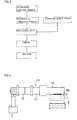
- the process and the mechanical structure with regard to the method of ultrasonic welding based on the "lateral vibration" are as illustrated in Figs. 3 and 4.
- the ultrasonic electric energy is transmitted (propagated) from an ultrasonic transmitter 11.
- the transmitted ultrasonic energy is then converted to the mechanical vibration energy by means of a treatment apparatus 13.
- the treatment apparatus 13 consists of, for example, a converter 15, a booster 17 and a horn 19.
- the pressing surface 19a applies pressure to the upper case 1 via the protrusions 21.
- the mechanical vibration energy as above described is applied to the upper case 1 and to the lower case 3 as illustrated in Fig.
- the present embodiment defines the angle of applying lateral vibration as 45° as indicated by arrow A in Fig. 2.
- the angle of 45° is defined according to the following ground.
- the present embodiment has the following advantages.
- the ultrasonic welding in the present embodiment based on the lateral vibration remarkably lessens the vibration propagated to the coil terminals inside the lower case 3. Consequently, the lateral vibration minimizes the possibility of being cut of the coil terminals, and protects the electromagnetic type of electroacoustic transducer against being lost of its function.
- the angle of application of the lateral vibration is defined as 45° , therefore the side walls 1a, 1b, 3a and 3b are prevented from being bent.
- the sufficient frictional heat can be equally generated at each of four sides of the welding surface 7, and the welding and fixing of the upper case 1 and the lower case 3 are surely carried out. Consequently, it is possible to use the thinner coil wire, or to minimize and the size and thickness of the resin case. Therefore the method of ultrasonic welding according to the present embodiment eventually contributes to the minimization of size and thickness of the electromagnetic type of electroacoustic transducer.
- a second embodiment of the present invention will be described with reference to Figs. 5 through 9.
- a welding surface 35 between a case 31 and a base member 33 in an oblong, rectangular shape in the second embodiment which is basically the same structure as that of the first embodiment. Therefore the lateral vibration is similarly applied to the case 31 and the base member 33, in the direction parallel to the welding surface 35, at the angle of 45° as illustrated in Fig. 6.
- Fig. 7 illustrates the structure inside the case 31 and the base member 33.
- a base 37 and a core 39 which are integrally formed as a "pole piece" on the base member 33 inside the case 31.
- a coil 41 is wound around a the core 39, and a support ring 43 is placed around the coil 41.
- Placed at the inner periphery of the support ring 43 namely, at the space between the support ring 43 and the coil 41, with a clearance 47 on the side of the coil 41) is a magnet 45.
- An elastic plate 53 provided with a magnetic piece 51 as an added mass is placed on a step portion 49 of the support ring 43.
- the electromagnetic type of electroacoustic transducer illustrated in Fig. 7 has the same structure as that of the electromagnetic type of electroacoustic transducer of the prior art illustrated in Fig. 14.
- Fig. 8 illustrates the structure before the ultrasonic welding based on the lateral vibration is carried out, in which the both step portions 31a and 33a are confronting and in contact with each other.
- a third embodiment of the present invention will now be described with reference to Figs. 10 and 11.
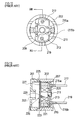
- a welding surface 65 between an upper case 61 and a lower case 63 has a round (circular or ring-like) shape in the third embodiment.
- the lateral vibration is then rotatively applied to the upper case 61 and to the lower case 63 in the direction parallel to the welding surface 65, namely, in the rotative (circumferential) direction of the welding surface 65, as indicated by arrow C in Fig. 11.
- the third embodiment applies the lateral vibration in the circumferential direction according to the following ground.
- the lateral vibration applied in the direction parallel to the welding surface 65 is the reciprocating movement in a predetermined direction, although such a reciprocating movement is effective to the cases of the first and the second embodiments, the reciprocating movement causes the large amount of resistant force at a side wall of the upper case 61, thus the side wall of the upper case 61 is bent, which may result in insufficient generation of frictional heat the side wall, eventually the desired welding cannot be carried out.
- the lateral vibration in the rotative direction in the circumferential direction as indicated by arrow C in Fig.
- Reference numeral 67 in Fig. 10 is a sound port.
- the process and the mechanical structure with regard to the method of ultrasonic welding based on the lateral vibration according to the third embodiment is the same as those of the first and the second embodiments as above described.
- any structure that converts the reciprocating movement in the lateral direction to the rotative movement in the lateral direction should be added to the treatment apparatus 13 in Fig. 4.
- the present invention is not limited to the first through third embodiments as described above.
- each embodiment refers to the resin case used for the electromagnetic type of electroacoustic transducer as the example of the resin case, the present invention can be applied to any other resin cases.
Landscapes
- Engineering & Computer Science (AREA)
- Mechanical Engineering (AREA)
- Lining Or Joining Of Plastics Or The Like (AREA)
- Electrostatic, Electromagnetic, Magneto- Strictive, And Variable-Resistance Transducers (AREA)
- Audible-Bandwidth Dynamoelectric Transducers Other Than Pickups (AREA)
Applications Claiming Priority (2)
| Application Number | Priority Date | Filing Date | Title |
|---|---|---|---|
| JP19570496A JP3877016B2 (ja) | 1996-07-05 | 1996-07-05 | 樹脂ケースの超音波溶着方法 |
| JP195704/96 | 1996-07-05 |
Publications (2)
| Publication Number | Publication Date |
|---|---|
| EP0816053A2 true EP0816053A2 (de) | 1998-01-07 |
| EP0816053A3 EP0816053A3 (de) | 1998-03-04 |
Family
ID=16345598
Family Applications (1)
| Application Number | Title | Priority Date | Filing Date |
|---|---|---|---|
| EP19970304804 Withdrawn EP0816053A3 (de) | 1996-07-05 | 1997-07-02 | Verfahren zum Ultraschallschweissen eines Kunststoffgehäuses |
Country Status (5)
| Country | Link |
|---|---|
| US (1) | US5830300A (de) |
| EP (1) | EP0816053A3 (de) |
| JP (1) | JP3877016B2 (de) |
| KR (1) | KR100584939B1 (de) |
| CN (1) | CN1128564C (de) |
Cited By (2)
| Publication number | Priority date | Publication date | Assignee | Title |
|---|---|---|---|---|
| EP1930148A1 (de) * | 2006-12-07 | 2008-06-11 | Telsonic Holding AG | Verwendung einer Vorrichtung zum torsionalen Ultraschallschweissen |
| WO2010100225A1 (de) * | 2009-03-05 | 2010-09-10 | Plastal Gmbh | Verfahren zur befestigung eines bauteils an ein kunststoffteil eines kraftfahrzeugs mit dem torsionalen ultraschallschweissverfahren |
Families Citing this family (17)
| Publication number | Priority date | Publication date | Assignee | Title |
|---|---|---|---|---|
| US6193833B1 (en) * | 1998-09-04 | 2001-02-27 | Spx Corporation | Method of laser welding transmission filter housing components |
| US6494976B1 (en) * | 1999-05-18 | 2002-12-17 | Denso Corporation | Ultrasonically joining apparatus and ultrasonically joining method |
| US6583364B1 (en) * | 1999-08-26 | 2003-06-24 | Sony Chemicals Corp. | Ultrasonic manufacturing apparatuses, multilayer flexible wiring boards and processes for manufacturing multilayer flexible wiring boards |
| KR20020072605A (ko) * | 2001-03-12 | 2002-09-18 | 김영주 | 몰딩성형구조를 갖는 주화케이스 및 그 주화케이스의제조방법 |
| EP1410988B1 (de) * | 2001-03-12 | 2008-11-19 | Shikoku Kakoki Co., Ltd. | Ultraschallwellendichtungsverfahren für behälter |
| WO2003074254A1 (en) * | 2002-02-28 | 2003-09-12 | Scimed Life Systems, Inc. | Ultrasonic assisted apparatus and process |
| US7204898B2 (en) * | 2004-07-23 | 2007-04-17 | Lmt Mercer Group Inc. | Thermoplastic fencing construction and method of assembly thereof |
| US8668797B2 (en) | 2004-07-23 | 2014-03-11 | Lmt Mercer Group Inc. | Method of assembly of thermoplastic fencing |
| US20060033091A1 (en) * | 2004-07-23 | 2006-02-16 | Lmt Mercer Group Inc. | Thermoplastic fencing construction and method of assembly thereof |
| US20070137020A1 (en) * | 2005-12-20 | 2007-06-21 | Ip Technologies Llc | Method and apparatus for forming a metallic container |
| US7748101B2 (en) | 2005-12-20 | 2010-07-06 | Ip Technologies Holdings, Llc | Method and apparatus for forming a metallic container |
| JP5052850B2 (ja) * | 2006-09-21 | 2012-10-17 | 豊達電機(香港)有限公司 | スピーカキャビネットの超音波溶着接合方法、およびそれによって作製されたスピーカキャビネット |
| JP2010258302A (ja) * | 2009-04-27 | 2010-11-11 | Texas Instr Japan Ltd | 超音波フリップチップ実装方法およびそれに用いられる基板 |
| JP5536560B2 (ja) * | 2010-06-25 | 2014-07-02 | ポリプラスチックス株式会社 | 溶着条件の決定方法 |
| DE102010043089A1 (de) * | 2010-10-29 | 2012-05-03 | Robert Bosch Gmbh | Siegelbacke zur Siegelung eines Packstoffs mittels Ultraschall |
| EP2457683A1 (de) * | 2010-11-25 | 2012-05-30 | Telsonic Holding AG | Torsionales Schweissen |
| EP3718647A1 (de) | 2019-04-01 | 2020-10-07 | Branson Ultraschall Niederlassung der Emerson Technologies GmbH & Co. oHG | Torsionshorn und ultraschallbearbeitungsverfahren unter verwendung des torsionshorns |
Family Cites Families (28)
| Publication number | Priority date | Publication date | Assignee | Title |
|---|---|---|---|---|
| US3376179A (en) * | 1964-06-12 | 1968-04-02 | Cavitron Ultrasonics Inc | Method and apparatus for high frequency joining or sealing of thermosoftening materials |
| US3623926A (en) * | 1969-03-26 | 1971-11-30 | Ultrasonic Systems | Ultrasonic method and apparatus for assembly of thermoplastic members |
| US3860468A (en) * | 1973-04-10 | 1975-01-14 | Du Pont | Angular welding process and apparatus |
| GB1524817A (en) * | 1975-08-15 | 1978-09-13 | Kerry Ultrasonics | Welding thermoplastics materials |
| US4088257A (en) * | 1977-02-14 | 1978-05-09 | Christiana Metals Corporation | Ultrasonic spot welder |
| US4326903A (en) * | 1980-12-05 | 1982-04-27 | Branson Ultrasonics Corporation | Method for securing parts together by ultrasonic energy |
| JPS57178826A (en) * | 1981-04-30 | 1982-11-04 | Akira Washida | Method of welding ethylene tetrafluoride resin by ultrasonic wave |
| FR2507531A1 (fr) * | 1981-06-12 | 1982-12-17 | Mecasonic Sa | Procede et dispositif de soudage de films en matiere plastique par ultrasons |
| DE3229076A1 (de) * | 1981-08-07 | 1983-03-24 | Pola Chemical Industries, Inc., Shizuoka | Verfahren und vorrichtung zum verschweissen des bodens eines rohrfoermigen behaelters aus kunstharz |
| DE3147255C2 (de) * | 1981-11-28 | 1986-08-28 | Licentia Patent-Verwaltungs-Gmbh, 6000 Frankfurt | Vorrichtung zum Verschweißen von Bauteilen unter Verwendung von Ultraschall, insbesondere von Solarzellenkontakten und Solarzellenverbindern |
| GB2134847B (en) * | 1983-02-04 | 1985-11-13 | Standard Telephones Cables Ltd | Assembly using ultrasonics |
| US4554034A (en) * | 1984-11-15 | 1985-11-19 | Battelle Memorial Institute | Bonding capsules |
| KR910000315B1 (ko) * | 1986-04-04 | 1991-01-24 | 가부시끼가이샤 니후꼬 | 초음파 용착방법 |
| US4767492A (en) * | 1986-04-18 | 1988-08-30 | Pola Chemical Industries, Inc. | Ultrasonic fuse-bonding sealing apparatus with improved contact surfaces |
| JPS62282914A (ja) * | 1986-05-31 | 1987-12-08 | Shinshin Shokai:Kk | 特音波溶着パタ−ン |
| JPS63221799A (ja) * | 1987-03-11 | 1988-09-14 | Matsushita Electric Ind Co Ltd | マイクロホンユニツト |
| JPH06103958B2 (ja) * | 1987-03-16 | 1994-12-14 | 松下電器産業株式会社 | マイクロホンユニツト |
| US4964941A (en) * | 1988-07-20 | 1990-10-23 | Storage Technology Corporation | Apparatus for mounting a magnetic head on a suspension arm |
| US5223063A (en) * | 1989-04-17 | 1993-06-29 | Kabushiki Kaisha Shinkawa | Method for bonding semiconductor elements to a tab tape |
| US5079387A (en) * | 1990-01-31 | 1992-01-07 | Emerson Electric Co. | Electrical component with enclosure and method of manufacture thereof |
| DE4015253A1 (de) * | 1990-05-12 | 1991-11-14 | Hoechst Ceram Tec Ag | Piezoelektrischer tongeber und verfahren zu seiner herstellung |
| JP2846512B2 (ja) * | 1991-08-22 | 1999-01-13 | 三菱電機株式会社 | カラー受像管のシャドウマスク |
| JPH0691756A (ja) * | 1992-01-24 | 1994-04-05 | Choonpa Kogyo Kk | 捩り振動を利用する超音波スウェージングツール |
| JP3190437B2 (ja) * | 1992-07-07 | 2001-07-23 | 富士写真光機株式会社 | 電子内視鏡用コネクタ |
| JP2592197B2 (ja) * | 1992-09-08 | 1997-03-19 | スター精密株式会社 | 樹脂ケースの超音波溶着方法 |
| JP3336372B2 (ja) * | 1993-11-10 | 2002-10-21 | 株式会社コーセー | 合成樹脂製品とその溶着方法 |
| JP3169153B2 (ja) * | 1993-12-28 | 2001-05-21 | トヨタ自動車株式会社 | プラスチック部材の接合方法 |
| DE4437677C2 (de) * | 1994-10-21 | 1997-12-04 | Mann & Hummel Filter | Verfahren zur Herstellung von Saugrohren und Saugrohr aus Kunststoff |
-
1996
- 1996-07-05 JP JP19570496A patent/JP3877016B2/ja not_active Expired - Fee Related
-
1997
- 1997-07-02 EP EP19970304804 patent/EP0816053A3/de not_active Withdrawn
- 1997-07-03 US US08/887,966 patent/US5830300A/en not_active Expired - Fee Related
- 1997-07-04 KR KR1019970031042A patent/KR100584939B1/ko not_active Expired - Fee Related
- 1997-07-07 CN CN97114537A patent/CN1128564C/zh not_active Expired - Fee Related
Cited By (3)
| Publication number | Priority date | Publication date | Assignee | Title |
|---|---|---|---|---|
| EP1930148A1 (de) * | 2006-12-07 | 2008-06-11 | Telsonic Holding AG | Verwendung einer Vorrichtung zum torsionalen Ultraschallschweissen |
| WO2008068281A1 (de) * | 2006-12-07 | 2008-06-12 | Telsonic Holding Ag | Verwendung einer vorrichtung zum torsionalen ultraschallschweissen |
| WO2010100225A1 (de) * | 2009-03-05 | 2010-09-10 | Plastal Gmbh | Verfahren zur befestigung eines bauteils an ein kunststoffteil eines kraftfahrzeugs mit dem torsionalen ultraschallschweissverfahren |
Also Published As
| Publication number | Publication date |
|---|---|
| CN1128564C (zh) | 2003-11-19 |
| JP3877016B2 (ja) | 2007-02-07 |
| KR100584939B1 (ko) | 2006-09-20 |
| EP0816053A3 (de) | 1998-03-04 |
| CN1174486A (zh) | 1998-02-25 |
| US5830300A (en) | 1998-11-03 |
| JPH1023597A (ja) | 1998-01-23 |
| KR980013517A (ko) | 1998-04-30 |
Similar Documents
| Publication | Publication Date | Title |
|---|---|---|
| US5830300A (en) | Method of ultrasonic welding for a resin case | |
| JP3421654B2 (ja) | ムービング磁石構造を有する電気−音響変換器及びその変換方法 | |
| JP4260333B2 (ja) | 電気音響変換器 | |
| US6668067B2 (en) | Electroacoustic transducer | |
| JP2001204096A (ja) | 電磁音響変換器およびその製造方法 | |
| US7316289B2 (en) | Electro-acoustic transducer and method of manufacturing transducer | |
| JP3602792B2 (ja) | 機械的音響クロスオーバ・ネットワークおよびそのトランスデューサ | |
| US3638052A (en) | Electroacoustic transducers of the bilaminar flexural vibrating type | |
| EP0688144B1 (de) | Verfahren zur Herstellung eines elektroakustischen Wandlers | |
| US7433486B2 (en) | Speaker and manufacturing method for the same | |
| JP6883216B2 (ja) | 音響変換装置及び音声出力機器 | |
| JPH09149494A (ja) | 電気音響変換器 | |
| JP2002152896A (ja) | マイクロスピーカ | |
| KR100987464B1 (ko) | 지향성 스피커 | |
| JP3844641B2 (ja) | 電気音響変換器及びその製造方法 | |
| JP3631935B2 (ja) | 電気音響変換器 | |
| JP4553278B2 (ja) | 多機能型発音体およびその製造方法 | |
| JP2001245390A (ja) | 電気音響変換器 | |
| JP6629460B2 (ja) | 発音装置およびその製造方法 | |
| CN213522360U (zh) | 发声装置 | |
| US3752941A (en) | Electroacoustic transducers | |
| KR100967853B1 (ko) | 다기능형 진동 액추에이터의 회로 기판 실장 구조 | |
| JP4115647B2 (ja) | 電気音響変換器 | |
| KR100328875B1 (ko) | 박판부저 및 그의 제조방법 | |
| JP3916995B2 (ja) | 電気音響変換器 |
Legal Events
| Date | Code | Title | Description |
|---|---|---|---|
| PUAI | Public reference made under article 153(3) epc to a published international application that has entered the european phase |
Free format text: ORIGINAL CODE: 0009012 |
|
| AK | Designated contracting states |
Kind code of ref document: A2 Designated state(s): FI SE |
|
| PUAL | Search report despatched |
Free format text: ORIGINAL CODE: 0009013 |
|
| AK | Designated contracting states |
Kind code of ref document: A3 Designated state(s): AT BE CH DE DK ES FI FR GB GR IE IT LI LU MC NL PT SE |
|
| 17P | Request for examination filed |
Effective date: 19980821 |
|
| AKX | Designation fees paid |
Free format text: FI SE |
|
| RBV | Designated contracting states (corrected) |
Designated state(s): FI SE |
|
| REG | Reference to a national code |
Ref country code: DE Ref legal event code: 8566 |
|
| 17Q | First examination report despatched |
Effective date: 19991202 |
|
| STAA | Information on the status of an ep patent application or granted ep patent |
Free format text: STATUS: THE APPLICATION IS DEEMED TO BE WITHDRAWN |
|
| 18D | Application deemed to be withdrawn |
Effective date: 20010713 |