EP0816134A2 - Procédé pour enlever les moyens d'étanchéité aux crevaisons d'un pneu, et appareil pour la mise en oeuvre du procédé - Google Patents
Procédé pour enlever les moyens d'étanchéité aux crevaisons d'un pneu, et appareil pour la mise en oeuvre du procédé Download PDFInfo
- Publication number
- EP0816134A2 EP0816134A2 EP97304399A EP97304399A EP0816134A2 EP 0816134 A2 EP0816134 A2 EP 0816134A2 EP 97304399 A EP97304399 A EP 97304399A EP 97304399 A EP97304399 A EP 97304399A EP 0816134 A2 EP0816134 A2 EP 0816134A2
- Authority
- EP
- European Patent Office
- Prior art keywords
- hose
- tyre
- container
- accordance
- valve
- Prior art date
- Legal status (The legal status is an assumption and is not a legal conclusion. Google has not performed a legal analysis and makes no representation as to the accuracy of the status listed.)
- Granted
Links
Images



Classifications
-
- B—PERFORMING OPERATIONS; TRANSPORTING
- B60—VEHICLES IN GENERAL
- B60C—VEHICLE TYRES; TYRE INFLATION; TYRE CHANGING; CONNECTING VALVES TO INFLATABLE ELASTIC BODIES IN GENERAL; DEVICES OR ARRANGEMENTS RELATED TO TYRES
- B60C29/00—Arrangements of tyre-inflating valves to tyres or rims; Accessories for tyre-inflating valves, not otherwise provided for
- B60C29/06—Accessories for tyre-inflating valves, e.g. housings, guards, covers for valve caps, locks, not otherwise provided for
- B60C29/062—Accessories for tyre-inflating valves, e.g. housings, guards, covers for valve caps, locks, not otherwise provided for for filling a tyre with particular materials, e.g. liquids
-
- B—PERFORMING OPERATIONS; TRANSPORTING
- B29—WORKING OF PLASTICS; WORKING OF SUBSTANCES IN A PLASTIC STATE IN GENERAL
- B29C—SHAPING OR JOINING OF PLASTICS; SHAPING OF MATERIAL IN A PLASTIC STATE, NOT OTHERWISE PROVIDED FOR; AFTER-TREATMENT OF THE SHAPED PRODUCTS, e.g. REPAIRING
- B29C73/00—Repairing of articles made from plastics or substances in a plastic state, e.g. of articles shaped or produced by using techniques covered by this subclass or subclass B29D
- B29C73/24—Apparatus or accessories not otherwise provided for
-
- B—PERFORMING OPERATIONS; TRANSPORTING
- B60—VEHICLES IN GENERAL
- B60C—VEHICLE TYRES; TYRE INFLATION; TYRE CHANGING; CONNECTING VALVES TO INFLATABLE ELASTIC BODIES IN GENERAL; DEVICES OR ARRANGEMENTS RELATED TO TYRES
- B60C17/00—Tyres characterised by means enabling restricted operation in damaged or deflated condition; Accessories therefor
-
- B—PERFORMING OPERATIONS; TRANSPORTING
- B29—WORKING OF PLASTICS; WORKING OF SUBSTANCES IN A PLASTIC STATE IN GENERAL
- B29C—SHAPING OR JOINING OF PLASTICS; SHAPING OF MATERIAL IN A PLASTIC STATE, NOT OTHERWISE PROVIDED FOR; AFTER-TREATMENT OF THE SHAPED PRODUCTS, e.g. REPAIRING
- B29C73/00—Repairing of articles made from plastics or substances in a plastic state, e.g. of articles shaped or produced by using techniques covered by this subclass or subclass B29D
- B29C73/16—Auto-repairing or self-sealing arrangements or agents
- B29C73/166—Devices or methods for introducing sealing compositions into articles
-
- B—PERFORMING OPERATIONS; TRANSPORTING
- B29—WORKING OF PLASTICS; WORKING OF SUBSTANCES IN A PLASTIC STATE IN GENERAL
- B29L—INDEXING SCHEME ASSOCIATED WITH SUBCLASS B29C, RELATING TO PARTICULAR ARTICLES
- B29L2030/00—Pneumatic or solid tyres or parts thereof
Definitions
- the present invention relates to a method of removing puncture sealing preparations from tyres and also to apparatus for carrying out the method.
- Sealing preparations are increasingly being used for tyres with punctures. They mainly contain colloidal dispersions of polymers in aqueous media. Thus, by way of example, polystyrene butadiene latexes, polyvinylacetate latexes and rubber latexes are used. Such a sealing preparation is described in the German patent application 195 45 935.0, which contains natural rubber latex and an adhesive resin.
- the sealing preparation is sprayed into the tyre via the tyre valve and the tyre is pumped up to a specific pressure by means of a propellant gas or compressor.
- the tyre is then run for a few kilometres, depending on the nature of the defect to distribute the sealing preparation within the interior of the tyre and to seal the defect. Thereafter the tyre may be fully inflated to its desired pressure.
- the so-sealed tyre must be later removed from the rim in a car repair workshop or at a tyre fitters.
- a considerably proportion of the sprayed-in sealing preparation is present in a liquid form within the interior of the tyre and can run out from the rim during the removal of the tyre.
- the sealing preparation is sticky, unpleasant and also smells of ammonia and contains natural rubber latex.
- the object of the present invention is to make available methods for removing puncture sealing preparations from tyres and also apparatus for carrying out the method.
- a method of removing puncture sealing compositions from a tyre characterised by allowing air pressure to flow out of the tyre via the valve, removing the tyre valve, introducing a hose into the tyre through the vale bore until the introduced hose end dips deeply into the sealing preparation contained in the tyre and generating a pressure differential so that the sealing preparation is removed through the hose.
- the pressure differential may be generated by generating depressed pressure in a container which is connected to the other hose end by which the sealing preparation is sucked out of the tyre into the container.
- This procedure can be repeated several times.
- a compressible container for example a bottle of soft plastic is used, having an opening to which a hose can be attached in an air-tight manner.
- the same container can be used as that from which the sealing preparation was sprayed into the tyre following a puncture, via a hose pushed onto the tyre valve, by compression of the container.
- the intermediate space between the hose and the valve bore is sealed off and an excess pressure is generated in the tyre by which the sealing preparation is propelled out of the tyre, via the hose, into the container which is connected to the hose.
- the hose end is connected to a pressure source outside of the tyre.
- An overpressure of 0.5 to 1 bar is preferably generated in the tyre with compressed air.
- the connection to the pressure source is interrupted and the hose is connected to the container into which the sealing preparation is pressed out of the tyre by the overpressure.
- the sealing off of the intermediate space between the hose and the valve bore can be achieved by using a rubber cone pushed onto the hose.
- a container provided with a vent opening, which is connected to a line which leads to one opening of a T-shaped connector and is provided with a blocking member.
- a hose clamp can be used.
- a pressure source is connected to the second opening of the T-shaped connector, with a non-return valve being provided between the connection piece and the pressure source.
- the hose whose other end dips into the sealing preparation in the tyre, is connected to the third opening to the T-shaped connector.
- Compressed air from the pressure source for example a compressor or a filling system present at filling stations, is first filled into the tyre via the T-shaped connector and the hose, with the blocking member in the line to the container being closed. Once the desired overpressure in the tyre is achieved, the blocking member in the line to the container is opened so that the sealing preparation is pushed out of the tyre through the hose into the container.
- a pressure relief valve is preferably provided in the line between the pressure source and the three-way cock. This line and also the connection between the three-way cock and the container can take the form of hoses.
- a connection between the pressure source and the hose introduced into the tyre is first produced by the three-way cock, whereas the line to the container is closed off.
- the three-way cock is moved into a position in which the connection to the pressure source is closed off, while the hose introduced into the tyre is connected to the line to the container.
- the sealing preparation is pressed into the container through the overpressure in the tyre.
- an overpressure is thus first generated in the tyre and the sealing preparation is subsequently pressed out of the tyre by the overpressure.
- Compressed air and sealing preparation are respectively supplied and led away through the same hose,
- the sealing preparation is pressed out of the tyre while the compressed air is being supplied. In this case only a slight overpressure needs to be generated in the tyre.
- a coaxial hose is dipped through the valve bore into the sealing preparation in the tyre.
- the inner hose is connected to the container for the reception of the sealing preparation.
- the outer hose is connected to the pressure source.
- the sealing preparation is pressed out of the interior of the tyre, via the inner hose, into the container by the compressed air introduced into the tyre between the inner and outer hose.
- the apparatus contains, in addition to the container provided with a vent opening and the pressure source, a coaxial plug connection and also a coaxial hose.
- a coaxial plug connection In this plug connection the inner hose opens into the line to the container and the outer hose into the connection to the pressure source.
- Support ribs can be provided between the inner hose and the wall of the outer hose.
- the tyre Before the tyre valve is removed, the tyre should be left to stand for a period of time on its tread with the valve in the six o'clock position and in a slightly inclined position in which the tyre side with the valve is somewhat higher than the side of the tyre remote from the valve. The free sealing preparation then collects during this time in the bottom of the tyre.
- the locking nut With full metal valves, the locking nut is removed and the valve is pushed into the tyre. With part metallic valves the valve is cut off above the rim with a knife and the remainder of the valve is pressed into the tyre, or the whole valve is removed with a dismantling lever. The hose is then introduced into the valve bore.
- the hose can be provided at the inserted end with a short metal tube in order to make the end heavier, and thus to guarantee that the hose end dips deeply into the sealing preparation.
- FIG 1 a part of a cut-away tyre is shown.
- the tyre 1 is positioned with a slight inclination on a support 2 so that the sealing preparation 3 collects at the bottom of the tyre towards the wall 4 of the tyre remote from the valve.
- the tyre valve has already been removed in Figure 1.
- the hose 6 is introduced into the tyre via the valve bore 5 so that the hose end dips deeply into the sealing preparation 3.
- the hose 6 is connected at its other end 8 in an air-tight manner to the bottle 9.
- the bottle 9 consists of soft plastic.
- the sealing preparation is sucked out of the tyre through the hose 6 into the bottle 9 by the depression in the bottle 9.
- the bottle 9 can be compressed several times in succession. It is held at least 20 cm beneath the support 2.
- the sealing preparation 3 has been sucked out of the tyre, the tyre can be removed from the rim.
- Figure 2 shows an embodiment in which the sealing preparation is pressed out of the tyre by overpressure.
- identical parts are designated with the same reference numerals as in Figure 1.
- the intermediate space between the hose 6 and the valve bore 5 is sealed off by a rubber cone 10 pushed onto the hose 6.
- 11 designates a three-way cock.
- the bottle 9 is connected to its first input or connection 12 via the hose 13.
- the bottle 9 is provided with a vent opening 14.
- a compressor 15 is connected via a line 16 to the second input or connection 17 of the three-way cock 11.
- the hose 6 is connected to the third input or connection 18 of the three-way cock 11. Its end 7 dips into the sealing preparation 3 in the tyre 1.
- a non-return valve 19 and a pressure relief valve 20 are arranged in the line 16.
- the three-way cock 11 is firstly brought into a position in which the connection between the compressor 15 and the hose 6 is established while the first connection 12 of the three-way cock 11 to the hose 13 is closed off. Compressed air is led from the compressor 15 via the hose 6 into the tyre 1 until an overpressure of 0.5 to 1 bar is produced in the tyre 1. The three-way cock 11 is then slowly brought into am position in which the connection to the compressor 15 is interrupted and a connection is established between the hose 6 and the hose 13. The sealing preparation 3 is pressed through the hose 6 and the hose 13 into the bottle 9 by the overpressure in the tyre 1.
- the three-way cock 11 is replaced by a coaxial plug connection 21 and the hose 6 is also replaced by a coaxial hose 22.
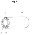
- Figure 3 shows the coaxial hose 22 which has an outer hose 23, an inner hose 24 and also support rubs 25 between the inner and outer hoses.
- FIG 4 there is shown a coaxial plug connection 21 in which the coaxial fluid flows in the inner and outer hoses are transferred into two streams alongside one another.
- the inner hose 24 opens into a line 26 at a telescope-like plug connection and the outer hose 23 opens into a ring-shaped passage 27 surrounding the line 26. Then hose 13 shown in Figure 2 is connected to the line 26 while the line 16 is connected to the ring-like passage 27.
- the plug connection is sealed off by sealing rings 28.
- the supply of compressed air into the tyre takes place at the same time as the removal of the sealing preparation 3.
- the compressed air is guided from the compressor 15 through the line 16, and the outer hose 23 into the tyre 1.
- the sealing preparation 3 is pressed into the bottle 9 on the further supply of compressed air through the inner hose 24 and the hose 13.
- a defoaming or anti-foaming agent for example on a silicon basis, may be introduced into the tyre.
- the introduction of the defoaming agent takes place after the valve has been removed or prior to the suction process.
- the introduction of the anti-foaming agent takes place after the valve removal or prior to the intermediate space between the hose and the valve bore being sealed off.
Landscapes
- Engineering & Computer Science (AREA)
- Mechanical Engineering (AREA)
- Tires In General (AREA)
- Heating, Cooling, Or Curing Plastics Or The Like In General (AREA)
Priority Applications (1)
| Application Number | Priority Date | Filing Date | Title |
|---|---|---|---|
| EP01124008A EP1174251B1 (fr) | 1996-06-25 | 1997-06-23 | Procédé pour enlever les moyens d'étanchéité aux crevaisons d'un pneu |
Applications Claiming Priority (2)
| Application Number | Priority Date | Filing Date | Title |
|---|---|---|---|
| DE19625372 | 1996-06-25 | ||
| DE19625372A DE19625372B4 (de) | 1996-06-25 | 1996-06-25 | Verfahren zum Entfernen von Pannen-Abdichtmitteln aus Reifen und Vorrichtung zur Durchführung des Verfahrens |
Related Child Applications (1)
| Application Number | Title | Priority Date | Filing Date |
|---|---|---|---|
| EP01124008.2 Division-Into | 2001-10-09 |
Publications (3)
| Publication Number | Publication Date |
|---|---|
| EP0816134A2 true EP0816134A2 (fr) | 1998-01-07 |
| EP0816134A3 EP0816134A3 (fr) | 1999-02-10 |
| EP0816134B1 EP0816134B1 (fr) | 2002-10-23 |
Family
ID=7797947
Family Applications (2)
| Application Number | Title | Priority Date | Filing Date |
|---|---|---|---|
| EP01124008A Expired - Lifetime EP1174251B1 (fr) | 1996-06-25 | 1997-06-23 | Procédé pour enlever les moyens d'étanchéité aux crevaisons d'un pneu |
| EP97304399A Expired - Lifetime EP0816134B1 (fr) | 1996-06-25 | 1997-06-23 | Procédé pour enlever les moyens d'étanchéité aux crevaisons d'un pneu, et appareil pour la mise en oeuvre du procédé |
Family Applications Before (1)
| Application Number | Title | Priority Date | Filing Date |
|---|---|---|---|
| EP01124008A Expired - Lifetime EP1174251B1 (fr) | 1996-06-25 | 1997-06-23 | Procédé pour enlever les moyens d'étanchéité aux crevaisons d'un pneu |
Country Status (4)
| Country | Link |
|---|---|
| US (1) | US5927348A (fr) |
| EP (2) | EP1174251B1 (fr) |
| JP (1) | JP3974224B2 (fr) |
| DE (3) | DE19625372B4 (fr) |
Families Citing this family (20)
| Publication number | Priority date | Publication date | Assignee | Title |
|---|---|---|---|---|
| JP3875523B2 (ja) * | 2001-07-19 | 2007-01-31 | 住友ゴム工業株式会社 | パンクシーリング剤の収容容器、及びそれを用いたパンク修理システム |
| JP3854841B2 (ja) * | 2001-10-12 | 2006-12-06 | 横浜ゴム株式会社 | タイヤパンク修理剤の処理方法 |
| US7981940B2 (en) * | 2004-05-26 | 2011-07-19 | Bridgestone Corporation | Method of treating sealing compound and apparatus for treating the same |
| JP4133945B2 (ja) * | 2004-06-28 | 2008-08-13 | 住友ゴム工業株式会社 | タイヤのパンクシーリング剤送給、抜取り装置 |
| JP2007331210A (ja) * | 2006-06-14 | 2007-12-27 | Bridgestone Corp | シーリング剤回収装置 |
| CN101821083A (zh) * | 2007-10-10 | 2010-09-01 | 株式会社普利司通 | 密封剂的回收方法及楔件 |
| JP4743327B2 (ja) * | 2010-01-15 | 2011-08-10 | 横浜ゴム株式会社 | パンク修理液の回収方法及び回収装置 |
| JP4743325B2 (ja) * | 2010-01-15 | 2011-08-10 | 横浜ゴム株式会社 | パンク修理液の回収方法及び回収装置 |
| JP4743328B2 (ja) * | 2010-01-15 | 2011-08-10 | 横浜ゴム株式会社 | パンク修理液の回収方法及び回収装置 |
| CN102712146B (zh) * | 2010-01-15 | 2016-01-06 | 横滨橡胶株式会社 | 爆胎修理液的回收方法以及回收装置 |
| JP4743326B2 (ja) | 2010-01-15 | 2011-08-10 | 横浜ゴム株式会社 | パンク修理液の回収方法 |
| JP5177208B2 (ja) * | 2010-11-19 | 2013-04-03 | 横浜ゴム株式会社 | パンク修理液の回収方法 |
| JP5229306B2 (ja) | 2010-11-19 | 2013-07-03 | 横浜ゴム株式会社 | パンク修理液の回収方法及び回収装置 |
| JP5304928B1 (ja) | 2012-06-18 | 2013-10-02 | 横浜ゴム株式会社 | タイヤの洗浄方法 |
| WO2017223173A1 (fr) | 2016-06-21 | 2017-12-28 | Bridgestone Americas Tire Operations, Llc | Procédés de traitement de surface de doublure intérieure, doublures intérieures obtenues à partir de tels procédés et pneus contenant de telles doublures intérieures |
| WO2018005810A1 (fr) | 2016-06-30 | 2018-01-04 | Bridgestone Americas Tire Operations, Llc | Procédés de traitement de revêtements internes, revêtements internes obtenus à partir de ceux-ci et pneus contenant de tels revêtements internes |
| WO2018112125A1 (fr) | 2016-12-15 | 2018-06-21 | Bridgestone Americas Tire Operations, Llc | Pneu contenant une étanchéité et processus associés |
| WO2018112117A2 (fr) | 2016-12-15 | 2018-06-21 | Bridgestone Americas Tire Operations, Llc | Procédés de production de revêtements contenant un polymère sur des calandrages intérieurs vulcanisés, procédés de production de pneus contenant de tels calandrages intérieurs, et pneus contenant de tels calandrages intérieurs |
| WO2018112179A1 (fr) | 2016-12-15 | 2018-06-21 | Bridgestone Americas Tire Operations, Llc | Nappe d'étanchéité avec barrière, pneu contenant celle-ci, et procédés associés |
| EP3719376A4 (fr) * | 2017-11-29 | 2021-07-21 | Active Tools International (HK) Ltd. | Élément de connexion, ensemble de connexion et machine de réparation de pneu |
Family Cites Families (22)
| Publication number | Priority date | Publication date | Assignee | Title |
|---|---|---|---|---|
| US2222047A (en) * | 1938-04-06 | 1940-11-19 | Goodrich Co B F | Apparatus for removing liquid from tires |
| US2488946A (en) * | 1945-03-17 | 1949-11-22 | Elias B Turpin | Apparatus for filling tires with air or liquid and withdrawing air or liquid therefrom |
| DE900527C (de) * | 1951-11-01 | 1953-12-28 | Friedrich Karrer | Pumpe fuer die Foerderung von Fluessigkeiten |
| US2926816A (en) * | 1953-06-30 | 1960-03-01 | Milford A Juten | Method and apparatus for dispensing fluid materials |
| US2929432A (en) * | 1957-06-20 | 1960-03-22 | Goodyear Tire & Rubber | Method and apparatus for filling tires with liquid |
| US3043348A (en) * | 1958-09-22 | 1962-07-10 | Wellsch Henry | Apparatus for introducing liquid into and removing from a pneumatic tube |
| US3021877A (en) * | 1959-09-08 | 1962-02-20 | Wellsch Henry | Means for servicing liquid-filled pneumatic tires |
| US3062590A (en) * | 1960-01-11 | 1962-11-06 | Roscoe E Turner | Ballast extraction method and apparatus |
| US3065774A (en) * | 1960-12-13 | 1962-11-27 | Gerald E Grimes | Device for inflating objects |
| DE1901328U (de) * | 1964-06-16 | 1964-09-24 | Peter Kwasny G M B H & Co | Mit reifenreparatur-mittel gefuellter aerosolbehaelter. |
| FR2072683A5 (fr) * | 1970-11-25 | 1971-09-24 | Arsac Albert | |
| US3729033A (en) * | 1971-03-22 | 1973-04-24 | Af Scheppman And Son Mfg Co | Compact portable tire servicing device |
| US3754580A (en) * | 1971-12-02 | 1973-08-28 | E Perry | Suction device |
| GB1534687A (en) * | 1975-03-06 | 1978-12-06 | Dunlop Ltd | Tyres |
| US3986520A (en) * | 1975-03-17 | 1976-10-19 | Caterpillar Tractor Co. | Apparatus and method for filling and removing liquid ballast from tires |
| DE7915390U1 (de) * | 1979-05-28 | 1979-10-04 | Wissner, Karl, 3354 Dassel | Vorrichtung zur pulsierenden entnahme von fluessigkeiten aus behaeltern |
| DE3717823A1 (de) * | 1986-05-30 | 1987-12-03 | Sisostra Kg | Vorrichtung zur entnahme einer fluessigkeitsprobe aus einem behaeltnis |
| US4811796A (en) * | 1987-08-17 | 1989-03-14 | Allen Stephen D | Fire fighting apparatus |
| US5390828A (en) * | 1993-05-20 | 1995-02-21 | Aptargroup, Inc. | Closure with two-part slidable dispensing cap |
| US5558257A (en) * | 1994-10-03 | 1996-09-24 | W. Braun Company | Oval integral slant pump |
| US5639319A (en) * | 1995-08-04 | 1997-06-17 | Daly; Glendon C. | Wheel with molasses ballast and method |
| DE29716453U1 (de) * | 1997-09-12 | 1999-01-21 | Alusuisse Bayrisches Druckguß-Werk GmbH & Co. KG, 85570 Markt Schwaben | Reparatursatz zum Reifenflicken |
-
1996
- 1996-06-25 DE DE19625372A patent/DE19625372B4/de not_active Expired - Lifetime
-
1997
- 1997-06-23 EP EP01124008A patent/EP1174251B1/fr not_active Expired - Lifetime
- 1997-06-23 DE DE69716517T patent/DE69716517T2/de not_active Expired - Lifetime
- 1997-06-23 EP EP97304399A patent/EP0816134B1/fr not_active Expired - Lifetime
- 1997-06-23 DE DE69734120T patent/DE69734120T2/de not_active Expired - Lifetime
- 1997-06-24 JP JP16744897A patent/JP3974224B2/ja not_active Expired - Lifetime
- 1997-06-25 US US08/882,115 patent/US5927348A/en not_active Expired - Lifetime
Also Published As
| Publication number | Publication date |
|---|---|
| US5927348A (en) | 1999-07-27 |
| DE69716517D1 (de) | 2002-11-28 |
| JPH1067212A (ja) | 1998-03-10 |
| DE69734120D1 (de) | 2005-10-06 |
| DE19625372A1 (de) | 1998-01-02 |
| DE19625372B4 (de) | 2006-05-24 |
| EP1174251A2 (fr) | 2002-01-23 |
| DE69734120T2 (de) | 2006-05-18 |
| EP1174251A3 (fr) | 2003-05-21 |
| DE69716517T2 (de) | 2003-02-27 |
| EP1174251B1 (fr) | 2005-08-31 |
| EP0816134B1 (fr) | 2002-10-23 |
| EP0816134A3 (fr) | 1999-02-10 |
| JP3974224B2 (ja) | 2007-09-12 |
Similar Documents
| Publication | Publication Date | Title |
|---|---|---|
| US5927348A (en) | Method of removing puncture sealing means from tires and apparatus for carrying out the method | |
| US3866654A (en) | Device for inflating tubeless automobile tires | |
| US5403417A (en) | Tire sealing methods and related apparatus | |
| US4765367A (en) | Valve assembly | |
| US5386857A (en) | Method of and apparatus for introducing pulverulent material into a tire | |
| AU782129B2 (en) | Sealing device | |
| US20010010237A1 (en) | Apparatus and method for filling a motor vehicle cooling system with coolant | |
| US5992476A (en) | Tire inflation apparatus | |
| CA1302213C (fr) | Pompe pour pneus, particulierement pour pneus de bycyclette | |
| US5247974A (en) | Pneumatic sealing device for waste disposal systems | |
| CN210970571U (zh) | 用于使轮胎就位在轮子上的气动轮胎就位器 | |
| GB1592714A (en) | Apparatus for evacuating and subsequently filling a hollow and closed system provided with only one open filling aperture with liquid | |
| US10131326B2 (en) | Tire mounting and inflation apparatus and method | |
| US2929432A (en) | Method and apparatus for filling tires with liquid | |
| US4308766A (en) | Liquid tire sealant injection tool | |
| WO2007041566A3 (fr) | Dispositif de joint d'etancheite a bascule et systeme pour le gonflage d'un pneumatique utilisant un tel dispositif | |
| US5967199A (en) | Pressurized brake bleed system | |
| JPH07139683A (ja) | パイプをふさぐ方法およびそのための装置 | |
| US5756882A (en) | Cap low leak testing system | |
| US5353831A (en) | Tube-piercing clamp on valve assembly | |
| CN210211890U (zh) | 一种用于车辆的自动补胎系统及车辆 | |
| US2311901A (en) | Air vent | |
| JP4323860B2 (ja) | タイヤのシーリング・ポンプアップ装置 | |
| JP2007331210A (ja) | シーリング剤回収装置 | |
| US3765469A (en) | Device for filling tubeless tires with a liquid |
Legal Events
| Date | Code | Title | Description |
|---|---|---|---|
| PUAI | Public reference made under article 153(3) epc to a published international application that has entered the european phase |
Free format text: ORIGINAL CODE: 0009012 |
|
| AK | Designated contracting states |
Kind code of ref document: A2 Designated state(s): DE FR GB |
|
| PUAL | Search report despatched |
Free format text: ORIGINAL CODE: 0009013 |
|
| AK | Designated contracting states |
Kind code of ref document: A3 Designated state(s): AT BE CH DE DK ES FI FR GB GR IE IT LI LU MC NL PT SE |
|
| 17P | Request for examination filed |
Effective date: 19990301 |
|
| RAP1 | Party data changed (applicant data changed or rights of an application transferred) |
Owner name: SUMITOMO RUBBER INDUSTRIES LIMITED |
|
| AKX | Designation fees paid |
Free format text: DE FR GB |
|
| 17Q | First examination report despatched |
Effective date: 20001130 |
|
| GRAG | Despatch of communication of intention to grant |
Free format text: ORIGINAL CODE: EPIDOS AGRA |
|
| GRAG | Despatch of communication of intention to grant |
Free format text: ORIGINAL CODE: EPIDOS AGRA |
|
| GRAH | Despatch of communication of intention to grant a patent |
Free format text: ORIGINAL CODE: EPIDOS IGRA |
|
| GRAH | Despatch of communication of intention to grant a patent |
Free format text: ORIGINAL CODE: EPIDOS IGRA |
|
| GRAA | (expected) grant |
Free format text: ORIGINAL CODE: 0009210 |
|
| AK | Designated contracting states |
Kind code of ref document: B1 Designated state(s): DE FR GB |
|
| REG | Reference to a national code |
Ref country code: GB Ref legal event code: FG4D |
|
| REF | Corresponds to: |
Ref document number: 69716517 Country of ref document: DE Date of ref document: 20021128 |
|
| ET | Fr: translation filed | ||
| PLBE | No opposition filed within time limit |
Free format text: ORIGINAL CODE: 0009261 |
|
| STAA | Information on the status of an ep patent application or granted ep patent |
Free format text: STATUS: NO OPPOSITION FILED WITHIN TIME LIMIT |
|
| 26N | No opposition filed |
Effective date: 20030724 |
|
| REG | Reference to a national code |
Ref country code: FR Ref legal event code: PLFP Year of fee payment: 20 |
|
| PGFP | Annual fee paid to national office [announced via postgrant information from national office to epo] |
Ref country code: GB Payment date: 20160622 Year of fee payment: 20 Ref country code: DE Payment date: 20160614 Year of fee payment: 20 |
|
| PGFP | Annual fee paid to national office [announced via postgrant information from national office to epo] |
Ref country code: FR Payment date: 20160516 Year of fee payment: 20 |
|
| REG | Reference to a national code |
Ref country code: DE Ref legal event code: R071 Ref document number: 69716517 Country of ref document: DE |
|
| REG | Reference to a national code |
Ref country code: GB Ref legal event code: PE20 Expiry date: 20170622 |
|
| PG25 | Lapsed in a contracting state [announced via postgrant information from national office to epo] |
Ref country code: GB Free format text: LAPSE BECAUSE OF EXPIRATION OF PROTECTION Effective date: 20170622 |