EP0816151A1 - Réservoir de carburant - Google Patents
Réservoir de carburant Download PDFInfo
- Publication number
- EP0816151A1 EP0816151A1 EP97110744A EP97110744A EP0816151A1 EP 0816151 A1 EP0816151 A1 EP 0816151A1 EP 97110744 A EP97110744 A EP 97110744A EP 97110744 A EP97110744 A EP 97110744A EP 0816151 A1 EP0816151 A1 EP 0816151A1
- Authority
- EP
- European Patent Office
- Prior art keywords
- fuel tank
- nozzle
- ring
- bracket cover
- groove
- Prior art date
- Legal status (The legal status is an assumption and is not a legal conclusion. Google has not performed a legal analysis and makes no representation as to the accuracy of the status listed.)
- Granted
Links
- 239000002828 fuel tank Substances 0.000 title claims abstract description 40
- 238000007789 sealing Methods 0.000 claims abstract description 36
- 230000000694 effects Effects 0.000 claims description 5
- 229920001169 thermoplastic Polymers 0.000 claims description 2
- 239000004416 thermosoftening plastic Substances 0.000 claims description 2
- 238000009434 installation Methods 0.000 claims 1
- 229920000098 polyolefin Polymers 0.000 abstract description 2
- 239000004033 plastic Substances 0.000 description 6
- 230000033001 locomotion Effects 0.000 description 5
- 239000000945 filler Substances 0.000 description 4
- 238000004519 manufacturing process Methods 0.000 description 3
- 239000000463 material Substances 0.000 description 3
- 238000007493 shaping process Methods 0.000 description 3
- 230000005540 biological transmission Effects 0.000 description 2
- 230000005489 elastic deformation Effects 0.000 description 2
- 239000000446 fuel Substances 0.000 description 2
- 230000008961 swelling Effects 0.000 description 2
- 230000009471 action Effects 0.000 description 1
- 238000007664 blowing Methods 0.000 description 1
- 230000008859 change Effects 0.000 description 1
- 238000010276 construction Methods 0.000 description 1
- 238000005520 cutting process Methods 0.000 description 1
- 238000000605 extraction Methods 0.000 description 1
- 238000001746 injection moulding Methods 0.000 description 1
- 239000007769 metal material Substances 0.000 description 1
- 238000000034 method Methods 0.000 description 1
- 239000002991 molded plastic Substances 0.000 description 1
- 230000035515 penetration Effects 0.000 description 1
- 230000002093 peripheral effect Effects 0.000 description 1
- 230000036316 preload Effects 0.000 description 1
- 230000008569 process Effects 0.000 description 1
- 230000008439 repair process Effects 0.000 description 1
- 238000005070 sampling Methods 0.000 description 1
- 239000012815 thermoplastic material Substances 0.000 description 1
Images
Classifications
-
- B—PERFORMING OPERATIONS; TRANSPORTING
- B60—VEHICLES IN GENERAL
- B60K—ARRANGEMENT OR MOUNTING OF PROPULSION UNITS OR OF TRANSMISSIONS IN VEHICLES; ARRANGEMENT OR MOUNTING OF PLURAL DIVERSE PRIME-MOVERS IN VEHICLES; AUXILIARY DRIVES FOR VEHICLES; INSTRUMENTATION OR DASHBOARDS FOR VEHICLES; ARRANGEMENTS IN CONNECTION WITH COOLING, AIR INTAKE, GAS EXHAUST OR FUEL SUPPLY OF PROPULSION UNITS IN VEHICLES
- B60K15/00—Arrangement in connection with fuel supply of combustion engines or other fuel consuming energy converters, e.g. fuel cells; Mounting or construction of fuel tanks
- B60K15/03—Fuel tanks
- B60K15/077—Fuel tanks with means modifying or controlling distribution or motion of fuel, e.g. to prevent noise, surge, splash or fuel starvation
-
- B—PERFORMING OPERATIONS; TRANSPORTING
- B60—VEHICLES IN GENERAL
- B60K—ARRANGEMENT OR MOUNTING OF PROPULSION UNITS OR OF TRANSMISSIONS IN VEHICLES; ARRANGEMENT OR MOUNTING OF PLURAL DIVERSE PRIME-MOVERS IN VEHICLES; AUXILIARY DRIVES FOR VEHICLES; INSTRUMENTATION OR DASHBOARDS FOR VEHICLES; ARRANGEMENTS IN CONNECTION WITH COOLING, AIR INTAKE, GAS EXHAUST OR FUEL SUPPLY OF PROPULSION UNITS IN VEHICLES
- B60K15/00—Arrangement in connection with fuel supply of combustion engines or other fuel consuming energy converters, e.g. fuel cells; Mounting or construction of fuel tanks
- B60K15/03—Fuel tanks
- B60K15/03177—Fuel tanks made of non-metallic material, e.g. plastics, or of a combination of non-metallic and metallic material
-
- B—PERFORMING OPERATIONS; TRANSPORTING
- B60—VEHICLES IN GENERAL
- B60K—ARRANGEMENT OR MOUNTING OF PROPULSION UNITS OR OF TRANSMISSIONS IN VEHICLES; ARRANGEMENT OR MOUNTING OF PLURAL DIVERSE PRIME-MOVERS IN VEHICLES; AUXILIARY DRIVES FOR VEHICLES; INSTRUMENTATION OR DASHBOARDS FOR VEHICLES; ARRANGEMENTS IN CONNECTION WITH COOLING, AIR INTAKE, GAS EXHAUST OR FUEL SUPPLY OF PROPULSION UNITS IN VEHICLES
- B60K15/00—Arrangement in connection with fuel supply of combustion engines or other fuel consuming energy converters, e.g. fuel cells; Mounting or construction of fuel tanks
- B60K15/03—Fuel tanks
- B60K15/04—Tank inlets
- B60K15/05—Inlet covers
Definitions
- the invention relates to a fuel tank according to the Preamble of claim 1.
- the invention is based on the object To design fuel tanks of the type described in the introduction, that the disadvantages of known such containers be avoided.
- the sealing ring is not intended to function as a structural part of the connection, thus preventing will have any effects on the sealing ring for example, by swelling and creeping of the person making it Materials the design of the connection between the fuel tank and cover and thus the effectiveness of the connection can influence.
- the sealing ring in through the bracket cover unstressed condition towards each other Part of the connection i.e. when arranged in the groove in the socket the fuel tank towards the bracket cover and when arranged in the groove in the bracket cover in the direction protrudes on the nozzle.
- the depth of the groove or the depth of penetration the undeformed, generally designed as an O-ring Sealing rings in the groove should therefore be chosen so that they are smaller is than the diameter of the sealing ring.
- the fastener securing the bracket cover in place can be designed as a strap. But it is also possible, the retaining ring of a plug closure on the nozzle to be arranged in the manner of a bayonet lock, which with a Clamping ring cooperates, the latter the bracket cover overlaps at its peripheral edge and towards the End face of the nozzle applied.
- Another possibility is the outside of the nozzle to be provided with a thread on which a union nut can be screwed on, the edge area of the edge area of the mounting cover spreads.
- z. B. arranged inside the fuel tank or in these leading pump sets, sampling lines, Level sensor or the like. Can be attached in a certain orientation with respect to its circumferential position to attach and connect to the fuel tank so a defined arrangement of those attached to the bracket cover or to ensure connected parts to the tank.
- This can be achieved in the usual way that on Socket, on the fasteners and on the bracket cover a positive locking means are provided which Attaching or installing the interacting parts only allow in predetermined positions so as to achieve that fuel pump, level indicator and other means and Facilities inside the fuel tank a certain Take up the spatial position, even after loosening the connection between Bracket cover and fuel tank when restoring the same is easily reproducible.
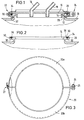
- FIG. 1 shows a section of a fuel tank 10, to be installed in a motor vehicle.
- This container 10 is provided with an outwardly projecting nozzle 12, the limited an opening 14.
- Such fuel tanks are generally in the blowing process from thermoplastic manufactured, the nozzle 12 at its free end is initially closed.
- the opening 14 will normally produced by a special cutting process.
- the opening 14 is closed by a mounting cover 16, which is usually made of a different material than the fuel tank 10.
- the bracket cover 16 can a metallic material, but possibly also from one Be made of plastic, which is made of plastic which is the fuel tank 10, distinguished by greater hardness.
- Blow molded plastic fuel tank are generally made from a polyolefin.
- the mounting cover 16 serves to hold line sections 18, by means of which a connection between the interior of the fuel tank 10 and the external environment becomes.
- line sections 18 can be parts of Extraction lines or other facilities that are within of the fuel tank 10 are arranged and outside of the fuel tank connections are required.
- connection of the bracket cover 16 with the socket 12 of the Fuel tank 10 takes place in the in FIGS. 1 and 2 illustrated embodiment by a two-part Clamping ring 20, the two essentially halves of which 20a, 20b via a hook connection that enables a pivoting movement 22 and over one opposite the connector Threaded bolts 24 arranged at 180 ° offset with nut 25 with one another can be connected and braced against each other.
- a two-part Clamping ring 20 the two essentially halves of which 20a, 20b via a hook connection that enables a pivoting movement 22 and over one opposite the connector Threaded bolts 24 arranged at 180 ° offset with nut 25 with one another can be connected and braced against each other.
- the connector 12 is on the end face with a circumferential groove 30 provided, the cross section of which is from the end boundary surface 28 evenly tapered towards the deepest point.
- the groove 30 serves to receive a sealing ring 34, the Cross-sectional dimensions in relation to the depth of the groove 30 are chosen so that the sealing ring on the one hand in unstressed State upwards a little above the frontal boundary surface 28 protrudes, as shown in FIG. 2, however on the other hand, the cross section of the sealing ring 34 is not larger is than that of the groove 30, so that in the shown in Fig. 1 Operating position of the parts in which the bracket cover 16 the frontal boundary surface 28 of the connector 12 rests, the sealing ring 34 is completely absorbed by the groove 30 becomes.
- the cross section of the groove can be slightly larger than that of the sealing ring 34. It is important that the latter by the the front-side boundary surface 28 seated mounting cover 16 the sealing ring 34 an elastic deformation and so that preload is sufficient to seal effect all the requirements of practical operation enough. On the other hand, the elastic deformation that the Sealing ring 34 through the on the end face 28 of the connector 12, the mounting cover 16, too low to cause a significant power transmission could take place because the bracket cover 16 with its edge area flat on the front boundary surface 28 of the nozzle 12 sits. With this arrangement the sealing ring 34 is not part of the load-bearing, ie load-bearing Structure of the connection between nozzle 12 and bracket cover 16.
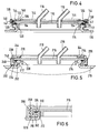
- FIG. 4 is correct with regard to the basic ones Arrangement of the essential parts with the embodiment according to FIGS. 1-3, so that for the same Parts also use the same reference numerals, however 4 are 100 higher in each case.
- the attachment takes place the bracket cover 116 using a clamp ring 136, which is provided with extensions 138 in its outer edge region that cooperate with a retaining ring 140, the outside is firmly attached to the nozzle 112.
- the clamping ring 136 and Retaining ring 140 act in the usual way in the manner of a bayonet lock together.
- the extensions 138 of the clamping ring become engaged with it in the course of a rotational movement the guide surface 142 of the respective holding section 144 on Bring ring 140 brought, due to a corresponding Inclination of the guide surfaces 142 in the circumferential direction in the course of the Rotational movement in the usual way the clamping of the interacting Parts done.
- the rotary motion can be using a suitable tool for which Engagement openings 146 are provided.
- the embodiment according to FIG. 5 is essentially correct with that shown in FIG. 1, so that the same parts with the same, are provided with 200 higher reference numerals.
- a difference is that the sealing ring 234 during execution 5 in a groove 230 on the end face of the nozzle 212 is arranged.
- the sealing ring in the bracket cover 216 be arranged, as vice versa in the embodiment according to Fig. 4, the groove for the sealing ring in the end face of the nozzle could be arranged.
- the groove for the sealing ring in the neck of the fuel tank should be preferred, since the nozzle is the necessary one anyway Minimum thickness to achieve sufficient rigidity must have, whereas it is in the arrangement of the groove in Bracket cover may be necessary for this the lid is thicker at least in the area of the groove to be carried out than would be necessary without a groove.
- FIG. 5 additionally has a fitting ring 248, which surrounds the socket 212 on the outside and its engages under flange-like outer edge 229.
- This pass ring which is manufactured separately and divided or otherwise in suitably designed so that it is bent apart can be used to be guided over the nozzle 212 only to the shape of the retaining ring 140 for the bayonet lock to simplify.
- Fig. 4 shows that the adjustment of the retaining ring 140 to the outer profile of the nozzle 112 requires several shaping processes, to some extent are expensive.
- the split fitting ring 248 must be referenced its inside boundary also on the outside Profile of the socket 212 can be adapted.
- the Fitting ring 248 on the outside so that it is essentially is flat and consequently requires only a small amount of shaping for the retaining ring 240, which on its side of the body of the fuel tank 210 can be provided with an inwardly bent flange 250. The latter engages under the fitting ring 248, so that the retaining ring 240 is positively connected to the fitting ring 248.
- the use of such a fitting ring 248 will depend on whether its manufacture or the use of a retaining ring is more complex, as with that according to FIG. 4, several Shaping steps must be subjected.
- the pass ring is conveniently made of a plastic that is harder than the plastic from which the fuel tank is made consists.
- the clamping ring 236 is for securing the same in the clamping position on the projections 238 with projections 254 provided at the end of its the firm connection between Effect bracket cover 216 and fuel tank 210
- Rotary movement in corresponding recesses on the retaining ring 240 intervene and thus bring about an additional form fit, the only by applying one against the the connection producing minimum rotational force can be.
- Such projections and recesses can of course also in the embodiment according to FIG. 4 may be provided.
- connection between the bracket cover is established 316 and the nozzle 312 of the fuel tank 310 by a union nut 356, which is attached to a threaded ring 358 is screwed on, the outside of the socket 312 surrounding this arranged and similar to the fitting ring 248 of the embodiment according to FIG. 5.
- the leg 352 of the threaded ring engages behind the flange-like outer edge 329 of the Stub 312, the front with the receiving the sealing ring 334 Groove 330 is provided.
- Threaded ring 358 is also so divided that it can be bent slightly can to lead it over the nozzle 312 and into the in Fig. 6 shown operating position.
- Threaded ring 358 and union nut 356 can be made of plastic, which, however, should be harder than the plastic from which the fuel tank 310 is made.
- Different from the other exemplary embodiments is that according to FIG. 6 with a roughly rectangular groove 330 in profile.
Landscapes
- Engineering & Computer Science (AREA)
- Life Sciences & Earth Sciences (AREA)
- Sustainable Development (AREA)
- Sustainable Energy (AREA)
- Chemical & Material Sciences (AREA)
- Combustion & Propulsion (AREA)
- Transportation (AREA)
- Mechanical Engineering (AREA)
- Cooling, Air Intake And Gas Exhaust, And Fuel Tank Arrangements In Propulsion Units (AREA)
- Closures For Containers (AREA)
Applications Claiming Priority (2)
| Application Number | Priority Date | Filing Date | Title |
|---|---|---|---|
| DE19627395A DE19627395A1 (de) | 1996-07-06 | 1996-07-06 | Kraftstoffbehälter |
| DE19627395 | 1996-07-06 |
Publications (2)
| Publication Number | Publication Date |
|---|---|
| EP0816151A1 true EP0816151A1 (fr) | 1998-01-07 |
| EP0816151B1 EP0816151B1 (fr) | 2000-05-17 |
Family
ID=7799192
Family Applications (1)
| Application Number | Title | Priority Date | Filing Date |
|---|---|---|---|
| EP97110744A Expired - Lifetime EP0816151B1 (fr) | 1996-07-06 | 1997-07-01 | Réservoir de carburant |
Country Status (7)
| Country | Link |
|---|---|
| US (1) | US6332555B1 (fr) |
| EP (1) | EP0816151B1 (fr) |
| BR (1) | BR9703878A (fr) |
| CA (1) | CA2209616C (fr) |
| DE (2) | DE19627395A1 (fr) |
| ES (1) | ES2149533T3 (fr) |
| PT (1) | PT816151E (fr) |
Cited By (9)
| Publication number | Priority date | Publication date | Assignee | Title |
|---|---|---|---|---|
| DE19842604A1 (de) * | 1998-09-17 | 2000-03-23 | Mannesmann Vdo Ag | Vorrichtung zur Ansaugung von Kraftstoff |
| EP1080971A3 (fr) * | 1999-09-02 | 2001-11-28 | Mannesmann VDO Aktiengesellschaft | Réservoir de carburant et procédé de fabrication d'un réservoir de carburant |
| JP2003054268A (ja) * | 2001-08-09 | 2003-02-26 | Horie Metal Co Ltd | 燃料タンクの開口部構造及びその開口部構造を有する燃料タンクの製造方法 |
| JP2003054270A (ja) * | 2001-08-09 | 2003-02-26 | Horie Metal Co Ltd | 燃料タンクの開口部構造 |
| EP1179444A3 (fr) * | 2000-08-07 | 2005-07-27 | Horie Kinzoku Kogyo Kabushiki Kaisha | Dispositif d'ouverture pour un réservoir de carburant |
| WO2013029839A3 (fr) * | 2011-08-29 | 2013-04-25 | Robert Bosch Gmbh | Dispositif pour le post-traitement des gaz d'échappement de moteurs à combustion interne et son procédé de fabrication |
| WO2016082996A1 (fr) * | 2014-11-27 | 2016-06-02 | Plastic Omnium Advanced Innovation And Research | Ensemble pour monter au moins un élément dans un réservoir d'un véhicule à moteur |
| WO2017076558A1 (fr) * | 2015-11-02 | 2017-05-11 | Ti Automotive Technology Center Gmbh | Réservoir muni d'un dispositif de renforcement |
| EP2628937B1 (fr) * | 2012-02-16 | 2020-06-24 | MAN Truck & Bus Österreich AG | Capot de recouvrement sur la circonférence externe d'un réservoir de carburant |
Families Citing this family (36)
| Publication number | Priority date | Publication date | Assignee | Title |
|---|---|---|---|---|
| DE19938131B4 (de) * | 1999-08-16 | 2006-08-31 | Ti Automotive Technology Center Gmbh | Kraftstoffbehälter |
| DE10060294A1 (de) * | 2000-12-05 | 2002-06-06 | Bosch Gmbh Robert | Vorrichtung zur Kraftstoffversorgung einer Brennkraftmaschine mit einem Kraftstoffilter |
| AT4938U1 (de) * | 2001-01-19 | 2002-01-25 | Tesma Motoren Getriebetechnik | Kraftstoffbehälter mit deckel |
| JP4040314B2 (ja) * | 2002-01-31 | 2008-01-30 | 株式会社エフティエス | 燃料タンクの開口部構造及びその開口部構造を有する燃料タンクの製造方法 |
| US6698613B2 (en) * | 2001-08-09 | 2004-03-02 | Fts Co., Ltd. | Opening structure of a fuel tank |
| US20030136507A1 (en) * | 2002-01-18 | 2003-07-24 | Thiel Steven A. | Thermoformed fuel tank fuel delivery system and assembly method |
| FR2845356B1 (fr) * | 2002-10-04 | 2005-05-13 | Inergy Automotive Systems Res | Platine porte-accessoires en matiere plastique pour corps creux thermoplastique, reservoir comprenant un accessoire monte sur une telle platine et procede pour fabriquer un reservoir a carburant comprenant une telle platine |
| US6834771B2 (en) * | 2002-10-28 | 2004-12-28 | Kyosan Denki Co., Ltd. | Resin component welding structure |
| CA2508734C (fr) * | 2002-12-06 | 2008-09-23 | Yachiyo Industry Co., Ltd. | Structure de montage de couvercle d'un conteneur en resine |
| US7478646B2 (en) * | 2003-01-31 | 2009-01-20 | Terry Borrenpohl | Valve outlet enclosure device |
| US7083065B2 (en) * | 2003-06-04 | 2006-08-01 | Millennium Industries Corporation | Tank assembly |
| DE10357357A1 (de) * | 2003-12-09 | 2005-07-07 | Volkswagen Ag | Kraftstofftank mit einem Verschluss |
| JP2006103624A (ja) * | 2004-10-08 | 2006-04-20 | Hitachi Ltd | 燃料タンク用蓋体ユニット |
| DE102005037683A1 (de) * | 2005-08-10 | 2007-02-15 | Bayerische Motoren Werke Ag | Kraftstofftank mit einer Montageöffnung |
| US7857323B1 (en) | 2006-02-24 | 2010-12-28 | Ti Group Automotive Systems, L.L.C. | Multi-piece seal |
| DE202007019641U1 (de) | 2006-06-08 | 2014-10-17 | Inergy Automotive Systems Research (Société A.) | System zur Lagerung von Motorgasadditiven |
| US7784637B2 (en) * | 2007-02-21 | 2010-08-31 | Ti Group Automotive Systems, L.L.C. | Multi-piece seal |
| JP4842856B2 (ja) * | 2007-02-27 | 2011-12-21 | 株式会社Fts | 燃料タンクの開口構造およびその製造方法 |
| US7854434B2 (en) * | 2007-04-12 | 2010-12-21 | Ti Group Automotive Systems, L.L.C. | Ring seal with axially-opposed radially-offset seal beads |
| DE202007009414U1 (de) * | 2007-07-04 | 2008-11-13 | pfm Produkte für die Medizin AG | Vorevakuierbarer oder vorevakuierter Behälter für medizinische Zwecke |
| US7975870B2 (en) * | 2007-08-29 | 2011-07-12 | Ti Group Automotive Systems, L.L.C. | Ring seal having sealing lobes |
| DE102007059826A1 (de) * | 2007-12-11 | 2009-06-18 | Volkswagen Ag | Kraftstoff-Fördereinrichtung |
| JP5160247B2 (ja) * | 2008-01-17 | 2013-03-13 | 本田技研工業株式会社 | 燃料タンク及び燃料ポンプ取付構造 |
| JP5179916B2 (ja) * | 2008-03-27 | 2013-04-10 | 本田技研工業株式会社 | 車両における樹脂製燃料タンク構造 |
| US8910815B2 (en) * | 2008-04-14 | 2014-12-16 | Ti Group Automotive Systems, L.L.C. | Cover for fuel system component and method of making |
| US8419021B2 (en) | 2008-10-31 | 2013-04-16 | Ti Group Automotive Systems, L.L.C. | Ring seal with insert |
| DE102011105197B4 (de) | 2011-06-17 | 2013-02-07 | Kautex Textron Gmbh & Co. Kg | Verschlusssystem an einem Kraftstoffbehälter |
| JP6177641B2 (ja) * | 2013-09-26 | 2017-08-09 | 株式会社ニフコ | 蓋体取付部材 |
| JP6221908B2 (ja) * | 2014-04-01 | 2017-11-01 | 株式会社デンソー | 燃料タンク蓋、および、それを有する燃料ポンプモジュール |
| EP2939859A1 (fr) * | 2014-04-28 | 2015-11-04 | Inergy Automotive Systems Research (Société Anonyme) | Système pour fixer un composant sur un récipient destiné à un véhicule automobile |
| ITUB20155359A1 (it) * | 2015-11-06 | 2017-05-06 | Eltek Spa | Componente di serbatoio, in particolare per sistemi di trattamento di gas di scarico di motori a combustione interna |
| US10197023B2 (en) * | 2016-11-17 | 2019-02-05 | Ford Global Technologies, Llc | Saddle fuel tank |
| DE102018120441B4 (de) * | 2017-09-28 | 2021-12-16 | Honda Motor Co., Ltd. | Aus Harz hergestellter Kraftstoffbehälter |
| DE102020117903A1 (de) * | 2020-07-07 | 2022-01-13 | Bayerische Motoren Werke Aktiengesellschaft | Flanschdeckel, Fördermodulanordnung, Betriebsmittelbehälter und modulares Betriebsmittelbehältersystem |
| US11964553B2 (en) | 2021-05-07 | 2024-04-23 | Hutchinson S.A. | Self-sealing coating for fuel tanks |
| US12085216B2 (en) | 2022-02-17 | 2024-09-10 | Arctic Cat Inc. | Multi-use fuel filler tube |
Citations (6)
| Publication number | Priority date | Publication date | Assignee | Title |
|---|---|---|---|---|
| DE2936773A1 (de) * | 1979-09-12 | 1981-04-02 | SWF-Spezialfabrik für Autozubehör Gustav Rau GmbH, 7120 Bietigheim-Bissingen | Brennstoffoerderanlage, insbesondere fuer kraftfahrzeuge |
| FR2596333A1 (en) * | 1986-03-25 | 1987-10-02 | Renault | Device for mounting a gauge, in a sealed fashion, on a fuel tank |
| FR2635055A1 (fr) * | 1988-08-02 | 1990-02-09 | Peugeot | Reservoir comportant une jauge |
| US4998639A (en) * | 1989-10-10 | 1991-03-12 | Solvay Automotive, Inc. | Fuel sender locking ring |
| DE9106732U1 (de) * | 1991-05-31 | 1991-09-19 | Wintershall Ag, 3500 Kassel | Spannringverschluß für Behälter |
| DE9205132U1 (de) * | 1991-06-21 | 1992-10-15 | Mauser-Werke GmbH, 5040 Brühl | Großvolumiges Deckelfaß |
Family Cites Families (19)
| Publication number | Priority date | Publication date | Assignee | Title |
|---|---|---|---|---|
| US506928A (en) * | 1893-10-17 | Cover-fastener for storage-vessels | ||
| US2553222A (en) * | 1943-05-03 | 1951-05-15 | Wallgren August Gunn Ferdinand | Sealing means for internalcombustion motors |
| DE1051253B (de) * | 1956-05-11 | 1959-02-26 | Maerkischer Armaturenbau G M B | Deckelverschluss fuer Behaelter, insbesondere fuer hohe Temperaturen und Druecke |
| GB1074653A (en) * | 1964-01-27 | 1967-07-05 | Jencons Scient Ltd | Improvements in or relating to desiccators |
| US3286871A (en) * | 1964-06-26 | 1966-11-22 | Walbro Corp | Fuel tank and mount |
| NL6918704A (fr) * | 1969-12-12 | 1971-06-15 | ||
| US3897884A (en) * | 1973-05-15 | 1975-08-05 | Richard F Lankenau | Drum closure |
| US4267940A (en) * | 1979-06-26 | 1981-05-19 | Purex Corporation | Removable clamp structure for tank sections which at times block said removal |
| US4377245A (en) * | 1980-10-06 | 1983-03-22 | Patty Blyde L | Closure for container |
| DE3135982A1 (de) * | 1981-09-11 | 1983-04-14 | Daimler-Benz Ag, 7000 Stuttgart | "kraftstoffbehaelter, insbesondere aus kunststoff bestehender kraftstoffbehaelter" |
| GB2124601B (en) * | 1982-08-07 | 1985-12-18 | Pm Plasmatic Ltd | Improvements in or relating to valve cap devices |
| US4664281A (en) * | 1985-10-15 | 1987-05-12 | Killark Electric Manufacturing Co. | Explosion proof enclosure |
| US4741453A (en) * | 1987-06-22 | 1988-05-03 | International Precision Components Corporation | Container and closure with fastening means |
| US4828300A (en) * | 1987-10-01 | 1989-05-09 | Olson Manufacturing Co. | Retaining ring |
| US5050764A (en) * | 1990-03-08 | 1991-09-24 | Pacesetter Infusion, Ltd. | Lateral compression sealing system and method of making seal |
| DE4240629C2 (de) * | 1992-12-03 | 1995-12-14 | Bayerische Motoren Werke Ag | Verschluß für einen Kunststoff-Flüssigkeitsbehälter, insbesondere für einen Kraftstoffbehälter eines Kraftfahrzeugs |
| FR2722077B1 (fr) * | 1994-07-06 | 1996-08-23 | Seb Sa | Dispositif de verrouillage/deverrouillage a machoires d'un couvercle sur une cuve |
| DE4434561C2 (de) * | 1994-09-28 | 1999-09-02 | Mannesmann Vdo Ag | Halteflansch zum Verschließen einer Tanköffnung |
| US5704510A (en) * | 1995-12-21 | 1998-01-06 | Feltman, Iii; Charles H. | Top lock lid |
-
1996
- 1996-07-06 DE DE19627395A patent/DE19627395A1/de not_active Ceased
-
1997
- 1997-06-30 US US08/886,001 patent/US6332555B1/en not_active Expired - Lifetime
- 1997-07-01 PT PT97110744T patent/PT816151E/pt unknown
- 1997-07-01 EP EP97110744A patent/EP0816151B1/fr not_active Expired - Lifetime
- 1997-07-01 DE DE59701694T patent/DE59701694D1/de not_active Expired - Lifetime
- 1997-07-01 ES ES97110744T patent/ES2149533T3/es not_active Expired - Lifetime
- 1997-07-03 CA CA002209616A patent/CA2209616C/fr not_active Expired - Lifetime
- 1997-07-07 BR BR9703878A patent/BR9703878A/pt not_active IP Right Cessation
Patent Citations (6)
| Publication number | Priority date | Publication date | Assignee | Title |
|---|---|---|---|---|
| DE2936773A1 (de) * | 1979-09-12 | 1981-04-02 | SWF-Spezialfabrik für Autozubehör Gustav Rau GmbH, 7120 Bietigheim-Bissingen | Brennstoffoerderanlage, insbesondere fuer kraftfahrzeuge |
| FR2596333A1 (en) * | 1986-03-25 | 1987-10-02 | Renault | Device for mounting a gauge, in a sealed fashion, on a fuel tank |
| FR2635055A1 (fr) * | 1988-08-02 | 1990-02-09 | Peugeot | Reservoir comportant une jauge |
| US4998639A (en) * | 1989-10-10 | 1991-03-12 | Solvay Automotive, Inc. | Fuel sender locking ring |
| DE9106732U1 (de) * | 1991-05-31 | 1991-09-19 | Wintershall Ag, 3500 Kassel | Spannringverschluß für Behälter |
| DE9205132U1 (de) * | 1991-06-21 | 1992-10-15 | Mauser-Werke GmbH, 5040 Brühl | Großvolumiges Deckelfaß |
Cited By (13)
| Publication number | Priority date | Publication date | Assignee | Title |
|---|---|---|---|---|
| DE19842604A1 (de) * | 1998-09-17 | 2000-03-23 | Mannesmann Vdo Ag | Vorrichtung zur Ansaugung von Kraftstoff |
| DE19842604C2 (de) * | 1998-09-17 | 2001-02-01 | Mannesmann Vdo Ag | Vorrichtung zur Ansaugung von Kraftstoff |
| EP1080971A3 (fr) * | 1999-09-02 | 2001-11-28 | Mannesmann VDO Aktiengesellschaft | Réservoir de carburant et procédé de fabrication d'un réservoir de carburant |
| EP1179444A3 (fr) * | 2000-08-07 | 2005-07-27 | Horie Kinzoku Kogyo Kabushiki Kaisha | Dispositif d'ouverture pour un réservoir de carburant |
| JP2003054268A (ja) * | 2001-08-09 | 2003-02-26 | Horie Metal Co Ltd | 燃料タンクの開口部構造及びその開口部構造を有する燃料タンクの製造方法 |
| JP2003054270A (ja) * | 2001-08-09 | 2003-02-26 | Horie Metal Co Ltd | 燃料タンクの開口部構造 |
| WO2013029839A3 (fr) * | 2011-08-29 | 2013-04-25 | Robert Bosch Gmbh | Dispositif pour le post-traitement des gaz d'échappement de moteurs à combustion interne et son procédé de fabrication |
| EP2628937B1 (fr) * | 2012-02-16 | 2020-06-24 | MAN Truck & Bus Österreich AG | Capot de recouvrement sur la circonférence externe d'un réservoir de carburant |
| WO2016082996A1 (fr) * | 2014-11-27 | 2016-06-02 | Plastic Omnium Advanced Innovation And Research | Ensemble pour monter au moins un élément dans un réservoir d'un véhicule à moteur |
| KR20160064022A (ko) * | 2014-11-27 | 2016-06-07 | 플라스틱 옴니엄 어드벤스드 이노베이션 앤드 리서치 | 컨테이너에 컴포넌트를 부착하기 위한 개선된 시스템을 갖는 어셈블리 |
| CN107000577A (zh) * | 2014-11-27 | 2017-08-01 | 全耐塑料高级创新研究公司 | 用于将至少一个构件安装在机动车辆的储箱中的组件 |
| WO2017076558A1 (fr) * | 2015-11-02 | 2017-05-11 | Ti Automotive Technology Center Gmbh | Réservoir muni d'un dispositif de renforcement |
| US10857874B2 (en) | 2015-11-02 | 2020-12-08 | Ti Automotive Technology Center Gmbh | Tank having a stiffening device |
Also Published As
| Publication number | Publication date |
|---|---|
| DE19627395A1 (de) | 1998-01-15 |
| ES2149533T3 (es) | 2000-11-01 |
| EP0816151B1 (fr) | 2000-05-17 |
| CA2209616A1 (fr) | 1998-01-06 |
| MX9705058A (es) | 1998-05-31 |
| CA2209616C (fr) | 2002-03-05 |
| BR9703878A (pt) | 1998-11-03 |
| PT816151E (pt) | 2000-10-31 |
| DE59701694D1 (de) | 2000-06-21 |
| US6332555B1 (en) | 2001-12-25 |
Similar Documents
| Publication | Publication Date | Title |
|---|---|---|
| EP0816151B1 (fr) | Réservoir de carburant | |
| DE19938131B4 (de) | Kraftstoffbehälter | |
| EP3692269B1 (fr) | Accouplement angulaire | |
| DE69407885T2 (de) | Lageranordnung für eine rotierende Welle einer Scheibenwischeranlage | |
| DE102021118920A1 (de) | Toleranzausgleichsvorrichtung | |
| EP2260224B1 (fr) | Dispositif de raccordement pour conduits de fluides dans la zone d'une traversée de cloison et élément de cloison | |
| EP4737748A1 (fr) | Élément de connexion et agencement de connexion | |
| EP0736406A1 (fr) | Corps d'auge | |
| EP1131222B1 (fr) | Bouchon pour le reservoir a carburant d'un vehicule automobile | |
| WO2011023425A1 (fr) | Unité de montage de couvercle | |
| EP1389691A1 (fr) | Ecrou en plastique pour monter à un élément de construction | |
| WO2018086839A1 (fr) | Vis de réglage | |
| DE3707196C1 (de) | Einschaeumbares Befestigungselement fuer eine geschaeumte Hartschaumverkleidung | |
| DE4421574C2 (de) | Ventil mit einem aus Kunststoff bestehenden Gehäuse und mit einem Gehäusestutzen | |
| EP0615086A1 (fr) | Procédé de fabrication d'un joint à lèvres | |
| EP1503096B1 (fr) | Organe de retenue pour la fixation d'au moins un palier | |
| DE4116779C2 (de) | Unterdruck-Bremskraftverstärker | |
| DE19615378C2 (de) | Dichtkörper für einen Anschluß zwischen einem Pfostenprofil und einem Fenster- oder Türrahmenprofil | |
| DE4408733B4 (de) | Wischarm für eine Scheibenwischeranlage, insbesondere für Kraftfahrzeuge | |
| DE102008005494B4 (de) | Steckverbindung mit einer Abdichtbarriere und Herstellungsverfahren einer derartigen Steckverbindung | |
| DE102010024501B4 (de) | Dichtelementebefestigungssystem für einen Druckbehälter, insbesondere einen Reaktordruckbehälter | |
| DE102008027510B4 (de) | Vorrichtung zur Befestigung zweier Komponenten einer für eine Stelleinrichtung vorgesehenen Antriebseinheit, insbesondere für einen Fensterheberantrieb, an einem tragenden Strukturelement eines Kraftfahrzeugs | |
| EP1697609B1 (fr) | Ferme-porte automatique integre dans le sol | |
| DE3937690C1 (fr) | ||
| EP3806248A1 (fr) | Prise électrique destinée au raccordement électrique d'une remorque à un véhicule automobile |
Legal Events
| Date | Code | Title | Description |
|---|---|---|---|
| PUAI | Public reference made under article 153(3) epc to a published international application that has entered the european phase |
Free format text: ORIGINAL CODE: 0009012 |
|
| AK | Designated contracting states |
Kind code of ref document: A1 Designated state(s): BE DE ES FR GB IT NL PT SE |
|
| RAP1 | Party data changed (applicant data changed or rights of an application transferred) |
Owner name: KAUTEX TEXTRON GMBH & CO. KG. |
|
| 17P | Request for examination filed |
Effective date: 19980623 |
|
| 17Q | First examination report despatched |
Effective date: 19980803 |
|
| AKX | Designation fees paid |
Free format text: AT BE CH DE DK ES FI FR GB GR IE IT LI LU MC NL PT SE |
|
| RBV | Designated contracting states (corrected) |
Designated state(s): BE DE ES FR GB IT NL PT SE |
|
| GRAG | Despatch of communication of intention to grant |
Free format text: ORIGINAL CODE: EPIDOS AGRA |
|
| GRAG | Despatch of communication of intention to grant |
Free format text: ORIGINAL CODE: EPIDOS AGRA |
|
| GRAH | Despatch of communication of intention to grant a patent |
Free format text: ORIGINAL CODE: EPIDOS IGRA |
|
| GRAH | Despatch of communication of intention to grant a patent |
Free format text: ORIGINAL CODE: EPIDOS IGRA |
|
| GRAA | (expected) grant |
Free format text: ORIGINAL CODE: 0009210 |
|
| AK | Designated contracting states |
Kind code of ref document: B1 Designated state(s): BE DE ES FR GB IT NL PT SE |
|
| REF | Corresponds to: |
Ref document number: 59701694 Country of ref document: DE Date of ref document: 20000621 |
|
| ITF | It: translation for a ep patent filed | ||
| GBT | Gb: translation of ep patent filed (gb section 77(6)(a)/1977) |
Effective date: 20000626 |
|
| ET | Fr: translation filed | ||
| REG | Reference to a national code |
Ref country code: PT Ref legal event code: SC4A Free format text: AVAILABILITY OF NATIONAL TRANSLATION Effective date: 20000711 |
|
| REG | Reference to a national code |
Ref country code: ES Ref legal event code: FG2A Ref document number: 2149533 Country of ref document: ES Kind code of ref document: T3 |
|
| PLBE | No opposition filed within time limit |
Free format text: ORIGINAL CODE: 0009261 |
|
| STAA | Information on the status of an ep patent application or granted ep patent |
Free format text: STATUS: NO OPPOSITION FILED WITHIN TIME LIMIT |
|
| 26N | No opposition filed | ||
| REG | Reference to a national code |
Ref country code: GB Ref legal event code: IF02 |
|
| PGFP | Annual fee paid to national office [announced via postgrant information from national office to epo] |
Ref country code: PT Payment date: 20040630 Year of fee payment: 8 |
|
| PGFP | Annual fee paid to national office [announced via postgrant information from national office to epo] |
Ref country code: NL Payment date: 20040722 Year of fee payment: 8 |
|
| PG25 | Lapsed in a contracting state [announced via postgrant information from national office to epo] |
Ref country code: PT Free format text: LAPSE BECAUSE OF NON-PAYMENT OF DUE FEES Effective date: 20060102 |
|
| PG25 | Lapsed in a contracting state [announced via postgrant information from national office to epo] |
Ref country code: NL Free format text: LAPSE BECAUSE OF NON-PAYMENT OF DUE FEES Effective date: 20060201 |
|
| NLV4 | Nl: lapsed or anulled due to non-payment of the annual fee |
Effective date: 20060201 |
|
| PGFP | Annual fee paid to national office [announced via postgrant information from national office to epo] |
Ref country code: IT Payment date: 20110726 Year of fee payment: 15 |
|
| REG | Reference to a national code |
Ref country code: DE Ref legal event code: R082 Ref document number: 59701694 Country of ref document: DE Representative=s name: KIERDORF RITSCHEL RICHLY PATENTANWAELTE PARTG , DE Ref country code: DE Ref legal event code: R082 Ref document number: 59701694 Country of ref document: DE Representative=s name: KIERDORF RITSCHEL PATENTANWAELTE PARTG MBB, DE Ref country code: DE Ref legal event code: R082 Ref document number: 59701694 Country of ref document: DE Representative=s name: FLEISCHER, GODEMEYER, KIERDORF & PARTNER, PATE, DE |
|
| PG25 | Lapsed in a contracting state [announced via postgrant information from national office to epo] |
Ref country code: IT Free format text: LAPSE BECAUSE OF NON-PAYMENT OF DUE FEES Effective date: 20120701 |
|
| REG | Reference to a national code |
Ref country code: DE Ref legal event code: R082 Ref document number: 59701694 Country of ref document: DE Representative=s name: KIERDORF RITSCHEL RICHLY PATENTANWAELTE PARTG , DE Ref country code: DE Ref legal event code: R082 Ref document number: 59701694 Country of ref document: DE Representative=s name: KIERDORF RITSCHEL PATENTANWAELTE PARTG MBB, DE |
|
| REG | Reference to a national code |
Ref country code: FR Ref legal event code: PLFP Year of fee payment: 19 |
|
| REG | Reference to a national code |
Ref country code: FR Ref legal event code: PLFP Year of fee payment: 20 |
|
| PGFP | Annual fee paid to national office [announced via postgrant information from national office to epo] |
Ref country code: GB Payment date: 20160721 Year of fee payment: 20 Ref country code: DE Payment date: 20160629 Year of fee payment: 20 |
|
| PGFP | Annual fee paid to national office [announced via postgrant information from national office to epo] |
Ref country code: SE Payment date: 20160720 Year of fee payment: 20 Ref country code: FR Payment date: 20160721 Year of fee payment: 20 |
|
| PGFP | Annual fee paid to national office [announced via postgrant information from national office to epo] |
Ref country code: BE Payment date: 20160720 Year of fee payment: 20 Ref country code: ES Payment date: 20160715 Year of fee payment: 20 |
|
| REG | Reference to a national code |
Ref country code: DE Ref legal event code: R071 Ref document number: 59701694 Country of ref document: DE |
|
| REG | Reference to a national code |
Ref country code: GB Ref legal event code: PE20 Expiry date: 20170630 |
|
| PG25 | Lapsed in a contracting state [announced via postgrant information from national office to epo] |
Ref country code: GB Free format text: LAPSE BECAUSE OF EXPIRATION OF PROTECTION Effective date: 20170630 |
|
| REG | Reference to a national code |
Ref country code: ES Ref legal event code: FD2A Effective date: 20180508 |
|
| PG25 | Lapsed in a contracting state [announced via postgrant information from national office to epo] |
Ref country code: ES Free format text: LAPSE BECAUSE OF EXPIRATION OF PROTECTION Effective date: 20170702 |