EP0816156B1 - Dispositif permettant l'actionnement manuel d'un organe de commande moteur d'un véhicule - Google Patents
Dispositif permettant l'actionnement manuel d'un organe de commande moteur d'un véhicule Download PDFInfo
- Publication number
- EP0816156B1 EP0816156B1 EP97110854A EP97110854A EP0816156B1 EP 0816156 B1 EP0816156 B1 EP 0816156B1 EP 97110854 A EP97110854 A EP 97110854A EP 97110854 A EP97110854 A EP 97110854A EP 0816156 B1 EP0816156 B1 EP 0816156B1
- Authority
- EP
- European Patent Office
- Prior art keywords
- rod
- rod part
- ring
- steering wheel
- actuating device
- Prior art date
- Legal status (The legal status is an assumption and is not a legal conclusion. Google has not performed a legal analysis and makes no representation as to the accuracy of the status listed.)
- Expired - Lifetime
Links
Images


Classifications
-
- B—PERFORMING OPERATIONS; TRANSPORTING
- B60—VEHICLES IN GENERAL
- B60W—CONJOINT CONTROL OF VEHICLE SUB-UNITS OF DIFFERENT TYPE OR DIFFERENT FUNCTION; CONTROL SYSTEMS SPECIALLY ADAPTED FOR HYBRID VEHICLES; ROAD VEHICLE DRIVE CONTROL SYSTEMS FOR PURPOSES NOT RELATED TO THE CONTROL OF A PARTICULAR SUB-UNIT
- B60W30/00—Purposes of road vehicle drive control systems not related to the control of a particular sub-unit, e.g. of systems using conjoint control of vehicle sub-units
- B60W30/18—Propelling the vehicle
-
- B—PERFORMING OPERATIONS; TRANSPORTING
- B60—VEHICLES IN GENERAL
- B60K—ARRANGEMENT OR MOUNTING OF PROPULSION UNITS OR OF TRANSMISSIONS IN VEHICLES; ARRANGEMENT OR MOUNTING OF PLURAL DIVERSE PRIME-MOVERS IN VEHICLES; AUXILIARY DRIVES FOR VEHICLES; INSTRUMENTATION OR DASHBOARDS FOR VEHICLES; ARRANGEMENTS IN CONNECTION WITH COOLING, AIR INTAKE, GAS EXHAUST OR FUEL SUPPLY OF PROPULSION UNITS IN VEHICLES
- B60K26/00—Arrangement or mounting of propulsion-unit control devices in vehicles
- B60K26/02—Arrangement or mounting of propulsion-unit control devices in vehicles of initiating means or elements
-
- B—PERFORMING OPERATIONS; TRANSPORTING
- B60—VEHICLES IN GENERAL
- B60R—VEHICLES, VEHICLE FITTINGS, OR VEHICLE PARTS, NOT OTHERWISE PROVIDED FOR
- B60R21/00—Arrangements or fittings on vehicles for protecting or preventing injuries to occupants or pedestrians in case of accidents or other traffic risks
- B60R21/02—Occupant safety arrangements or fittings, e.g. crash pads
- B60R21/16—Inflatable occupant restraints or confinements designed to inflate upon impact or impending impact, e.g. air bags
- B60R21/20—Arrangements for storing inflatable members in their non-use or deflated condition; Arrangement or mounting of air bag modules or components
- B60R21/203—Arrangements for storing inflatable members in their non-use or deflated condition; Arrangement or mounting of air bag modules or components in steering wheels or steering columns
-
- B—PERFORMING OPERATIONS; TRANSPORTING
- B60—VEHICLES IN GENERAL
- B60W—CONJOINT CONTROL OF VEHICLE SUB-UNITS OF DIFFERENT TYPE OR DIFFERENT FUNCTION; CONTROL SYSTEMS SPECIALLY ADAPTED FOR HYBRID VEHICLES; ROAD VEHICLE DRIVE CONTROL SYSTEMS FOR PURPOSES NOT RELATED TO THE CONTROL OF A PARTICULAR SUB-UNIT
- B60W2540/00—Input parameters relating to occupants
- B60W2540/10—Accelerator pedal position
-
- B—PERFORMING OPERATIONS; TRANSPORTING
- B60—VEHICLES IN GENERAL
- B60W—CONJOINT CONTROL OF VEHICLE SUB-UNITS OF DIFFERENT TYPE OR DIFFERENT FUNCTION; CONTROL SYSTEMS SPECIALLY ADAPTED FOR HYBRID VEHICLES; ROAD VEHICLE DRIVE CONTROL SYSTEMS FOR PURPOSES NOT RELATED TO THE CONTROL OF A PARTICULAR SUB-UNIT
- B60W2710/00—Output or target parameters relating to a particular sub-units
- B60W2710/06—Combustion engines, Gas turbines
Definitions
- the invention relates to a device for manually accelerating in motor vehicles according to the preamble of the claim 1.
- a hand throttle ring has, which is concentric to the steering wheel of a motor vehicle is arranged, the hand throttle ring with a center Rod connected by the hollow steering column of the Steering wheel runs.
- the rod is mounted so that the hand throttle ring is freely rotatable relative to the steering wheel.
- the hand throttle ring is used to accelerate against an energy storage device from the zero position down towards the Hub part of the steering wheel pressed, the stroke of the rod
- the accelerator pedal is actuated via a suitable mechanism. In the Release of the steering gas ring leads the energy storage back to the zero position.
- a major advantage of the known hand throttle ring is in that it can be turned independently of the steering wheel. This allows the hand throttle ring to be held and the steering wheel can be released when the motor vehicle, e.g. comes out of a tight curve, the Steering wheel alone returns to the starting position and then can be touched again. On a normal trip for example, both hands remain on the freeway Steering wheel and at the same time on the depressed hand throttle ring.
- the known hand throttle ring described is particularly suitable also for motorsport (e.g. mountain races etc.).
- the known hand throttle ring described can be used in today's Motor vehicles are not used in the middle an airbag is arranged in the space enclosed by the steering wheel is.
- a problem with this known Setup is that the feeler levers are not arranged around the entire inner circumference of the steering wheel are so that at least in the zero position of the steering wheel View of the fittings or display devices released becomes. For this reason, the operation of the feeler lever is open limited an area that is significantly smaller than 360 ° is.
- the feeler levers are at least partially rotated so that they cover the display devices mentioned. Since the partial arc bearing the feeler levers with respect to the steering wheel is not freely rotatable, the related advantages described with FR-PS 1 135 356 Steering of the motor vehicle can not be achieved.
- Another one The problem is that the feeler levers mentioned which have the shape of aluminum parts, relatively large and are bulky so that they do not in the event of an accident give in. Injuries, especially in the head area, are therefore to fear.
- the object of the present invention is a To improve the establishment of the type mentioned at the outset, that it can be used in motor vehicles that in have an airbag in the space enclosed by the steering wheel, at the same time that by a free rotation of the known Hand throttle ring achievable with regard to the steering Advantages are achievable.
- the main advantage is that the hand throttle ring the device according to the invention in relation to the steering wheel is freely rotatable, so that the vehicle is particularly easy to steer is.
- the vehicle is tight when exiting Manageable curves.
- One with the present facility equipped vehicle can therefore also be used by disabled people racing, for example for mountain trips become.
- the hand throttle ring of the invention Facility is closed and therefore closed by everyone Pages can be operated.
- the present is advantageous Furnishings designed to fit into the existing ones Space between an airbag and a steering wheel easily can be integrated, with a sufficiently large Stroke of the actuator can be achieved.
- the actuator in the distance between the hub part of the Steering wheel in the area of the steering column and the bottom of the airbag can be arranged, which in the worst case is only about 15 mm is.
- a major advantage is that the device according to the invention in the event of an accident the entire ring part is pushed in parallel to the steering column being, with the entire joint mechanism within the steering wheel in the space between the airbag and the hub part the steering wheel is arranged.
- the ring part bends in the event of an impact, the covering part of the ring part has a cushioning effect. Injuries from the above and non-compliant parts are therefore not too fear. In the event of an impact, the entire disappears Installation behind the level of the steering wheel rim.
- the device according to the invention is simply constructed and also easily into existing ones Motor vehicles can be retrofitted.
- the actuator of the invention Mechanism to set the accelerator pedal and / or an electrical potentiometer, for example a Linear potentiometer, actuated to generate an actuating signal become.
- the hand throttle ring of the device according to the invention is designed so that he the vehicle fittings covered as little as possible.
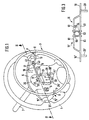
- FIG. 1 the steering wheel of a motor vehicle is 1 designated.
- the steering wheel 1 is attached to a hub part 5, this in turn schematically on one in FIG shown steering column 7 is mounted.
- an airbag 9 according to FIG.
- the present device is essentially in accordance with Figure 1 shows a hand throttle ring 3, a linkage and an actuator 11 on.
- the linkage comprises a first rod part connected to a ring part 13 of the hand gas ring 3 15 on, starting from the hand throttle ring 3 or Ring part 13 laterally on the airbag 9 in the between Hub part 5 and the airbag 9 space formed Side of the steering column 7 passes through.
- To adapt to the first rod part 15 be curved.
- the free end of the first rod part 15 is pivotable about a pivot point 17 with respect to the one end of a second rod part 19 is mounted, starting from runs from the pivot point 17 into the space 21, the between the floor 23 of the airbag 9 and the steering column 7 surrounding area 25 of the hub part 5.
- This Room 21 has existing steering wheel arrangements in the Direction of the axis of the steering column 7 has a dimension that is on the order of at least about 15 mm.
- the hub part 5 screwed to an external thread 8 of the steering column 7.
- the Airbag 9 is in with the help of mounting screws 10 Bores 6 screwed, which are in projections 12 of the hub part 5 are located, the distance between the bottom 23 of the airbag 9 and that adjacent to the steering column 7 Create area 25.
- the free end of the second rod part 19 forms the actuator 11 up to the area of an opening 27 protrudes, which is located in the hub part 5 and an access to the inside of the steering column 7.
- the second rod part 19 In the area of the actuator 11 is the second rod part 19 with a rod part 29 connected to it in a bore 31 of a Holding block 33 mounted on the area 25 of the hub part 5 is attached.
- a Holding block 33 mounted on the area 25 of the hub part 5 is attached.
- the rod part 29 extends vertically to the longitudinal axis of the second rod part 19.
- the pivot points are preferably 17th and 17 'formed in that at the corresponding ends the rod parts 15, 15 'and 19, 19' each have a flange 41 or 43 is arranged, each aligned with each other Have bores 44 through which a pivot point 17, 17 'forming pin is guided.
- the shell part 45 which consists of a plastic material, with a upholstered annular cover part 47 covered.
- the hand throttle ring 3 When moving the hand throttle ring 3 in the direction on the steering wheel 1 it is important that the hand throttle ring 3 is so elastic that it twists the rod parts 15, 19 and 15 ', 19' about the axis of the rod part 29, 29 'permits resilient deformation. More specifically during this movement the hand throttle ring will go to the maximum Outward movement of the pivot point 17, 17 'around the attachment locations O of the rod parts 15, 15 'on the ring part 13 elastic twisted (arrows P in Figure 1), so that the ring part 13 in total from its level towards the steering column 7 is bent out.
- a control rod 51 by the actuator 11, 11 ' is moved axially.
- the control rod 51 in the space between the area 25 of the hub part 5 and the bottom 23 of the airbag 9 located Head part 53, which has a circumferential groove 54, in which engages a pin 55 of the actuator 11, 11 '.
- the control rod 51 is therefore used to operate the gas pulled forward when the hand throttle ring 3 is in the direction of the airbag is pressed.
- a potentiometer 69 When using an electrical signal to operate the gas the help of a potentiometer 69 is to be generated the actuating arm 71 of this potentiometer 69 mechanically on Actuator 11 or 11 'or to a control rod 19, 19 'coupled.
- a potentiometer is shown in FIG 69, the actuating arm 71 thereof via an actuating rod 73 is coupled to the rod part 19.
- the rod part 19 in the by Broken line L pivoted position shown, where the control lever 71 for generating the electrical signal is rotated.
- the connecting pin 75 ' can also be attached to one Actuator 11 to be fixed and in an elongated hole 77 ' engage the other actuator 11 '.
- the rod part 29 and / or 29 ' actuates a rotary potentiometer 69' (FIG. 1).
- the end of the rod part 29, 29 ' engages directly on the axis of rotation 71 'of the rotary potentiometer on. A radial load on the rotary potentiometer 69 ' thereby prevented.
- control rod 51 has at its end region or head part 53 instead of the circumferential groove 54 (FIG. 2) Cross bore 154 in which a spherical part from each side 155, 155 'engages that at the free end of the actuator 11 or 11 'is attached.
- the spherical parts 155, 155 ' are expediently formed by steel balls, which preferably have a diameter of about 4 mm own and welded to the actuating members 11 are. Details of Figure 6, which are already related with the other figures are explained in the corresponding Designated way.
- the first rod part 15 has on its a flange 410 toward the end facing the second rod part in which an elongated hole 411 is provided.
- the second The rod part 19 faces the first rod part 15 facing side one of an upper flange 510 and one Lower flange 511 arranged congruently with it existing fork part, between which the flange 410 of the first rod part 15 engages.
- the flanges 510, 511 and 410 are aligned parallel to each other.
- the elongated hole 411 preferably runs along the longitudinal axis of the second rod part 19 when the first and extend the second rod part perpendicular to each other. It is pointed out that the fork part also on the first Rod part 15 and the flange 410 on the second rod part 19 can be arranged.
- the slot can also be the first Rod part 15 and the pin the second rod part 19 assigned.
Landscapes
- Engineering & Computer Science (AREA)
- Automation & Control Theory (AREA)
- Transportation (AREA)
- Mechanical Engineering (AREA)
- Air Bags (AREA)
- Steering Controls (AREA)
- Arrangement Or Mounting Of Propulsion Units For Vehicles (AREA)
- Vibration Prevention Devices (AREA)
- Auxiliary Drives, Propulsion Controls, And Safety Devices (AREA)
- Control Of Vehicle Engines Or Engines For Specific Uses (AREA)
- Fluid-Damping Devices (AREA)
- Mechanical Control Devices (AREA)
Claims (26)
- Dispositif pour la commande manuelle de l'accélération dans des véhicules automobiles, avec un volant (1), une partie moyeu (5) liée au volant (1) et un cercle d'accélérateur à main (3) qui peut être déplacé à l'encontre de la force d'un accumulateur d'énergie et agit sur un organe d'actionnement (11, 11', 69, 71, 73), un mécanisme (15, 17, 19, 29) étant prévu entre le cercle d'accélérateur à main (3) et l'organe d'actionnement (11, 11', 69, 71, 73), caractérisé en ce que qu'un coussin gonflable est logé dans la chambre intérieure définie par la partie moyeu (5), en ce que le cercle d'accélérateur à main (3) comporte une partie cercle (13) qui est solidaire du mécanisme et en ce que le mécanisme est disposé dans la chambre entre le coussin gonflable (9) et la partie moyeu (5).
- Dispositif selon la revendication 1, caractérisé en ce que le mécanisme (15, 17, 19, 29) est un mécanisme articulé formé d'un premier élément de tringlerie (15), qui est fixé à la partie cercle (13) par l'une de ses extrémités, d'un deuxième élément de tringlerie (19), qui est lié par l'une de ses extrémités à l'autre extrémité du premier élément de tringlerie (15) avec possibilité de pivotement autour d'un point d'articulation (17), et d'un élément en forme de tige (29), en ce que l'élément en forme de tige (29) est lié à la partie terminale de l'autre extrémité du deuxième élément de tringlerie (19), s'étend perpendiculairement à l'axe du volant (1) et est monté sur la partie moyeu (5) avec possibilité de pivotement autour de son axe longitudinal.
- Dispositif selon la revendication 1, caractérisé en ce que l'élément en forme de tige (29) est monté dans un perçage (31) d'un bloc de montage (33) fixé à la partie moyeu (5).
- Dispositif selon la revendication 2 ou 3, caractérisé en ce qu'un mécanisme articulé (15', 17', 19', 29') supplémentaire, similaire, comprenant un premier élément de tringlerie (15'), un deuxième élément de tringlerie (19'), un point d'articulation (17') et un élément en forme de tige (29') est prévu dans une position diamétralement opposée au mécanisme articulé (15, 17, 19, 29).
- Dispositif selon une des revendications 1 à 4, caractérisé en ce qu'un élément formant coquille (45) est disposé sur la partie cercle (13) avec possibilité de coulissement libre dans la direction périphérique de celui-ci.
- Dispositif selon une des revendications 1 à 5, caractérisé en ce que l'organe d'actionnement (11) se présente sous la forme d'un élément actionnable par le mécanisme articulé qui est couplé mécaniquement à une tige de commande (51) disposée à l'intérieur du tube de direction (7) du volant (1).
- Dispositif selon la revendication 6, caractérisé en ce que l'élément est lié à l'autre extrémité du deuxième élément de tringelerie (19, 19') et, du côté éloigné du point d'articulation (17, 17'), s'étend au-delà de l'élément en forme de tige (29, 29') et est couplé mécaniquement à un élément formant tête (53) lié à la tige de commande (51), qui est disposé dans la chambre entre la portion (25) de la partie moyeu (5) entourant le tube de direction (7) et le fond (23) du coussin gonflable (9).
- Dispositif selon la revendication 7, caractérisé en ce que l'élément formant tête (53) comporte une gorge périphérique (54) dans laquelle s'engage un doigt (55) lié à l'organe d'actionnement (11).
- Dispositif selon la revendication 7, caractérisé en ce que l'élément formant tête (53) comporte un trou transversal (154) dans lequel s'engage un élément sphérique (155) lié à l'organe d'actionnement (11).
- Dispositif selon la revendication 8, caractérisé en ce que l'organe d'actionnement (11), à son extrémité libre, présente deux éléments (61, 61) espacés l'un de l'autre, qui enserrent une zone latérale de l'élément formant tête (53), de telle sorte que le doigt (55) tenu entre lesdits éléments pénètre dans la gorge périphérique (54) de l'élément formant tête (3).
- Dispositif selon une des revendications 1 à 10, caractérisé en ce que, pour produire un signal électrique de réglage pour un moyen d'entraínement actionnant la pédale d'accélérateur, il est prévu comme organe d'actionnement un potentiomètre (69) électrique couplé au mouvement du mécanisme articulé.
- Dispositif selon la revendication 11, caractérisé en ce qu'un bras de réglage (71) du potentiomètre (69) est relié à la deuxième tige de commande (19, 19') ou à l'organe d'actionnement (11, 11') du mécanisme articulé et/ou du mécanisme articulé supplémentaire.
- Dispositif selon une des revendications 6 à 11, caractérisé en ce qu'en l'absence de la tige de commande (51) les organes d'actionnement (11, 11') du mécanisme articulé (15, 17, 19, 29) et du mécanisme articulé (15', 17', 19', 29') supplémentaire sont couplés mécaniquement entre eux.
- Dispositif selon la revendication 13, caractérisé en ce que les organes d'actionnement (11, 11') se chevauchent et présentent chacun un trou oblong (77), et en ce qu'un axe de liaison (75) est engagé dans les trous oblongs (77) mutuellement alignés.
- Dispositif selon la revendication 13, caractérisé en ce que les organes d'actionnement (11, 11') se chevauchent, et en ce qu'un axe de liaison (75) est fixé à l'un des organes d'actionnement (11) et pénètre dans un trou oblong (77') aménagé dans l'autre organe d'actionnement (11').
- Dispositif selon une des revendications 5 à 15, caractérisé en ce que l'élément formant coquille (45) s'étend sur plus de 180° du pourtour de la partie cercle (13) et présente une fente (46) qui s'étend dans sa direction périphérique et dans laquelle est disposée la première tige de commande (15, 15').
- Dispositif selon la revendication 13, caractérisé en ce que la fente (46) est aménagée du côté de l'élément formant coquille (45) tourné vers le volant.
- Dispositif selon une des revendications 1 à 17, caractérisé en ce que l'élément formant coquille (45) est muni d'un élément d'habillage (47).
- Dispositif selon la revendication 183, caractérisé en ce que l'élément d'habillage (47) est un élément rembourré.
- Dispositif selon une des revendications 1 à 197, caractérisé en ce que la partie cercle (13) est en acier.
- Dispositif selon une des revendications 2 à 20, caractérisé en ce que le premier élément de tringlerie (15, 15') est courbé de manière telle qu'il s'adapte à l'espace entre le coussin gonflable (9) et la partie moyeu (5).
- Dispositif selon une des revendications 11 à 21, caractérisé en ce que le potentiomètre (69') est un potentiomètre rotatif, dont l'axe (71') est solidaire en rotation de l'extrémité libre de l'élément en forme de tige (29, 29').
- Dispositif selon une des revendications 1 à 22, caractérisé en ce que le point d'articulation (17) est formé par un premier élément formant flasque (410) fixé à l'extrémité du premier élément de tringlerie (15) tournée vers le deuxième élément de tringlerie (19), en ce que l'élément formant flasque (410) comporte un trou oblong (411) dans lequel pénètre un doigt (512) fixé à un troisième et/ou quatrième élément formant flasque (510, 511) qui sont fixés en étant espacés l'un de l'autre à l'extrémité du deuxième élément de tringlerie (19) tournée vers le premier élément de tringlerie (15), en ce que le premier élément formant flasque est monté entre les deuxième et troisième éléments formant flasque, le doigt (512), lors d'une rotation du deuxième élément de tringlerie (19) autour de l'axe de l'élément en forme de tige (29), pouvant glisser dans le trou oblong (411) aux fins d'empêcher une transmission d'efforts du premier élément de tringlerie vers le deuxième.
- Dispositif selon une des revendications 1 à 22, caractérisé en ce que le point d'articulation (17) est formé par un premier élément formant flasque fixé à l'extrémité du deuxième élément de tringlerie tournée vers le premier élément de tringlerie, en ce que l'élément formant flasque comporte un trou oblong dans lequel pénètre un doigt fixé à un troisième et/ou quatrième élément formant flasque, qui sont fixés en étant espacés l'un de l'autre à l'extrémité du premier élément de tringlerie tournée vers le deuxième élément de tringlerie, en ce que le premier élément formant flasque est monté entre les deuxième et troisième éléments formant flasque, le doigt, lors d'une rotation du deuxième élément de tringlerie autour de l'axe de l'élément en forme de tige, pouvant glisser dans le trou oblong (411) aux fins d'empêcher une transmission d'efforts du premier élément de tringlerie vers le deuxième.
- Dispositif selon une des revendications 23 ou 24, caractérisé en ce que le trou oblong s'étend parallèlement à l'axe longitudinal du deuxième élément de tringlerie.
- Dispositif selon une des revendications 23 à 25, caractérisé en ce que les premier et deuxième éléments de tringlerie sont mutuellement perpendiculaires.
Applications Claiming Priority (2)
| Application Number | Priority Date | Filing Date | Title |
|---|---|---|---|
| DE19626625 | 1996-07-02 | ||
| DE19626625A DE19626625A1 (de) | 1996-07-02 | 1996-07-02 | Einrichtung zum manuellen Gasgeben bei Kraftfahrzeugen |
Publications (3)
| Publication Number | Publication Date |
|---|---|
| EP0816156A2 EP0816156A2 (fr) | 1998-01-07 |
| EP0816156A3 EP0816156A3 (fr) | 1999-02-10 |
| EP0816156B1 true EP0816156B1 (fr) | 2002-10-16 |
Family
ID=7798716
Family Applications (1)
| Application Number | Title | Priority Date | Filing Date |
|---|---|---|---|
| EP97110854A Expired - Lifetime EP0816156B1 (fr) | 1996-07-02 | 1997-07-01 | Dispositif permettant l'actionnement manuel d'un organe de commande moteur d'un véhicule |
Country Status (6)
| Country | Link |
|---|---|
| US (1) | US5947227A (fr) |
| EP (1) | EP0816156B1 (fr) |
| JP (1) | JPH10181378A (fr) |
| AT (1) | ATE226155T1 (fr) |
| DE (2) | DE19626625A1 (fr) |
| ES (1) | ES2185841T3 (fr) |
Families Citing this family (10)
| Publication number | Priority date | Publication date | Assignee | Title |
|---|---|---|---|---|
| IT1309126B1 (it) * | 1999-07-30 | 2002-01-16 | Guidosimplex Snc Di Giancarlo | Dispositivo di comando manuale, in particolare per l'accelerazione. |
| RU2246411C2 (ru) * | 2002-09-11 | 2005-02-20 | Открытое акционерное общество "Автоагрегат" | Устройство для ручного управления приводом акселератора |
| IT1393423B1 (it) * | 2009-03-23 | 2012-04-20 | Guidosimplex S R L | Dispositivo di comando di acceleratore a cerchiello. |
| CN101559723B (zh) * | 2009-06-02 | 2012-06-13 | 温志朝 | 一种控制按钮在方向盘上的汽车手控油门器 |
| DE102009057806A1 (de) | 2009-12-10 | 2011-07-21 | Kempf, Martine, Calif. | Verfahren und Einrichtung zum manuellen Gasgeben bei Kraftfahrzeugen |
| KR101567233B1 (ko) * | 2014-08-19 | 2015-11-06 | 현대자동차주식회사 | 장애인용 싱글 링크 타입 드라이브 보조 시스템 |
| CN106564525B (zh) * | 2016-11-08 | 2018-08-17 | 深圳市沃特玛电池有限公司 | 汽车及其方向盘 |
| US10836339B2 (en) * | 2018-09-25 | 2020-11-17 | Ford Global Technologies, Llc | Airbag including reinforcements |
| JP7434731B2 (ja) * | 2019-06-18 | 2024-02-21 | マツダ株式会社 | 運転補助装置 |
| JP7676780B2 (ja) | 2021-01-13 | 2025-05-15 | マツダ株式会社 | 運転補助装置 |
Family Cites Families (8)
| Publication number | Priority date | Publication date | Assignee | Title |
|---|---|---|---|---|
| US1593876A (en) * | 1925-04-29 | 1926-07-27 | Learmont Ray | Steering-wheel throttle and spark control |
| US2228393A (en) * | 1938-01-27 | 1941-01-14 | Morrell Q Leaming | Throttle valve control apparatus |
| FR1135356A (fr) * | 1955-07-11 | 1957-04-26 | Système de doubles commandes manuelles pour automobiles à l'usage des invalides | |
| IT1189041B (it) * | 1981-06-24 | 1988-01-28 | Giancarlo Venturini | Dispositivo per trasformare in un comando manuale il comando a pedale dell'acceleratore di un autoveicolo |
| FR2597038B1 (fr) * | 1986-04-11 | 1991-02-22 | Okey | Dispositif a anneau de commande manuelle d'acceleration pour vehicule a moteur |
| JP2760248B2 (ja) * | 1992-04-24 | 1998-05-28 | 豊田合成株式会社 | エアバッグ装置を備えたステアリングホイール |
| IT1262377B (it) * | 1993-07-16 | 1996-06-19 | Giancarlo Venturini | Struttura per l'accelerazione manuale in un autoveicolo. |
| IT230454Y1 (it) * | 1993-10-06 | 1999-06-07 | Linea Guida Srl | Dispositivo di comando dell'accelleratore per autovetture destinate ad utenti privi dell'uso degli arti inferiori |
-
1996
- 1996-07-02 DE DE19626625A patent/DE19626625A1/de not_active Withdrawn
-
1997
- 1997-07-01 AT AT97110854T patent/ATE226155T1/de not_active IP Right Cessation
- 1997-07-01 DE DE59708473T patent/DE59708473D1/de not_active Expired - Fee Related
- 1997-07-01 ES ES97110854T patent/ES2185841T3/es not_active Expired - Lifetime
- 1997-07-01 EP EP97110854A patent/EP0816156B1/fr not_active Expired - Lifetime
- 1997-07-01 US US08/886,508 patent/US5947227A/en not_active Expired - Lifetime
- 1997-07-02 JP JP9177316A patent/JPH10181378A/ja active Pending
Also Published As
| Publication number | Publication date |
|---|---|
| DE19626625A1 (de) | 1998-01-08 |
| EP0816156A2 (fr) | 1998-01-07 |
| DE59708473D1 (de) | 2002-11-21 |
| EP0816156A3 (fr) | 1999-02-10 |
| US5947227A (en) | 1999-09-07 |
| JPH10181378A (ja) | 1998-07-07 |
| ATE226155T1 (de) | 2002-11-15 |
| ES2185841T3 (es) | 2003-05-01 |
Similar Documents
| Publication | Publication Date | Title |
|---|---|---|
| DE3890516C2 (de) | Verstellbares Lenkrad | |
| DE69306521T2 (de) | Lagesperrvorrichtung für eine verstellbare Lenksäule zum Beispiel eines Kraftfahrzeuges und Lenksäuleneinrichtung mit so einer Vorrichtung | |
| DE2919062C2 (fr) | ||
| DE102005058428B4 (de) | Stoßdämpfende Vorrichtung für Bremspedale | |
| DE69300030T2 (de) | Einstellbare Lenksäuleneinheit für ein Kraftfahrzeug. | |
| DE19921552C2 (de) | Betätigungspedal für die Bremsanlage eines Straßenfahrzeuges | |
| EP0843630B1 (fr) | Dispositif pour separer la fixation d'une pedale de la carrosserie d'un vehicule a moteur | |
| EP2034384A2 (fr) | Agencement de pédale destiné à l'actionnement d'un embrayage | |
| DE3010409A1 (de) | Umspannvorrichtung fuer ein kupplungspedal | |
| DE1555465B1 (de) | Einstellbare Lenksaeule fuer Kraftfahrzeuge | |
| DE4022529C2 (de) | Säulenschalteinrichtung mit Schutzvorrichtung | |
| EP0816156A2 (fr) | Dispositif permettant l'actionnement manuel d'un organe de commande moteur d'un véhicule | |
| EP0356789B1 (fr) | Interrupteur électrique, en particulier monté sur la colonne de direction d'un véhicule | |
| DE4139496C2 (de) | Gaspedalvorrichtung | |
| EP0904990A1 (fr) | Unité d'actionnement | |
| EP1546837B1 (fr) | Dispositif a pedale ajustable | |
| DE2922109C2 (de) | Bremsbetätigungseinrichtung für Parkbremsen | |
| DE10257631B4 (de) | Verstellbares Fußhebelwerk | |
| DE60201307T2 (de) | Einstellvorrichtung zum Verstellen der Lage eines Pedals | |
| DE2740727A1 (de) | Lenksaeule fuer fahrzeuge | |
| DE69002331T2 (de) | Verstellbares lenkrad. | |
| DE19701184B4 (de) | Pedalanordnung für Fahrzeuge | |
| EP1272377A1 (fr) | Ensemble pedale atraumatique | |
| DE60100820T2 (de) | Pedalanordnung für Fahrzeuge | |
| DE102017200986A1 (de) | Pedalanordnung für ein Kraftfahrzeug mit einer Sicherheitseinrichtung |
Legal Events
| Date | Code | Title | Description |
|---|---|---|---|
| PUAI | Public reference made under article 153(3) epc to a published international application that has entered the european phase |
Free format text: ORIGINAL CODE: 0009012 |
|
| AK | Designated contracting states |
Kind code of ref document: A2 Designated state(s): AT BE CH DE DK ES FI FR GB GR IE IT LI LU MC NL PT SE |
|
| PUAL | Search report despatched |
Free format text: ORIGINAL CODE: 0009013 |
|
| AK | Designated contracting states |
Kind code of ref document: A3 Designated state(s): AT BE CH DE DK ES FI FR GB GR IE IT LI LU MC NL PT SE |
|
| 17P | Request for examination filed |
Effective date: 19990608 |
|
| AKX | Designation fees paid |
Free format text: AT BE CH DE DK ES FI FR GB GR IE IT LI LU MC NL PT SE |
|
| 17Q | First examination report despatched |
Effective date: 20010223 |
|
| GRAG | Despatch of communication of intention to grant |
Free format text: ORIGINAL CODE: EPIDOS AGRA |
|
| GRAG | Despatch of communication of intention to grant |
Free format text: ORIGINAL CODE: EPIDOS AGRA |
|
| GRAH | Despatch of communication of intention to grant a patent |
Free format text: ORIGINAL CODE: EPIDOS IGRA |
|
| GRAH | Despatch of communication of intention to grant a patent |
Free format text: ORIGINAL CODE: EPIDOS IGRA |
|
| GRAA | (expected) grant |
Free format text: ORIGINAL CODE: 0009210 |
|
| AK | Designated contracting states |
Kind code of ref document: B1 Designated state(s): AT BE CH DE DK ES FI FR GB GR IE IT LI LU MC NL PT SE |
|
| PG25 | Lapsed in a contracting state [announced via postgrant information from national office to epo] |
Ref country code: IE Free format text: LAPSE BECAUSE OF FAILURE TO SUBMIT A TRANSLATION OF THE DESCRIPTION OR TO PAY THE FEE WITHIN THE PRESCRIBED TIME-LIMIT Effective date: 20021016 Ref country code: GR Free format text: LAPSE BECAUSE OF FAILURE TO SUBMIT A TRANSLATION OF THE DESCRIPTION OR TO PAY THE FEE WITHIN THE PRESCRIBED TIME-LIMIT Effective date: 20021016 Ref country code: FI Free format text: LAPSE BECAUSE OF FAILURE TO SUBMIT A TRANSLATION OF THE DESCRIPTION OR TO PAY THE FEE WITHIN THE PRESCRIBED TIME-LIMIT Effective date: 20021016 |
|
| REF | Corresponds to: |
Ref document number: 226155 Country of ref document: AT Date of ref document: 20021115 Kind code of ref document: T |
|
| REG | Reference to a national code |
Ref country code: GB Ref legal event code: FG4D Free format text: NOT ENGLISH |
|
| REG | Reference to a national code |
Ref country code: CH Ref legal event code: EP |
|
| REG | Reference to a national code |
Ref country code: IE Ref legal event code: FG4D Free format text: GERMAN |
|
| REF | Corresponds to: |
Ref document number: 59708473 Country of ref document: DE Date of ref document: 20021121 |
|
| PG25 | Lapsed in a contracting state [announced via postgrant information from national office to epo] |
Ref country code: SE Free format text: LAPSE BECAUSE OF FAILURE TO SUBMIT A TRANSLATION OF THE DESCRIPTION OR TO PAY THE FEE WITHIN THE PRESCRIBED TIME-LIMIT Effective date: 20030116 Ref country code: PT Free format text: LAPSE BECAUSE OF FAILURE TO SUBMIT A TRANSLATION OF THE DESCRIPTION OR TO PAY THE FEE WITHIN THE PRESCRIBED TIME-LIMIT Effective date: 20030116 Ref country code: DK Free format text: LAPSE BECAUSE OF FAILURE TO SUBMIT A TRANSLATION OF THE DESCRIPTION OR TO PAY THE FEE WITHIN THE PRESCRIBED TIME-LIMIT Effective date: 20030116 |
|
| GBT | Gb: translation of ep patent filed (gb section 77(6)(a)/1977) |
Effective date: 20030210 |
|
| REG | Reference to a national code |
Ref country code: ES Ref legal event code: FG2A Ref document number: 2185841 Country of ref document: ES Kind code of ref document: T3 |
|
| ET | Fr: translation filed | ||
| REG | Reference to a national code |
Ref country code: IE Ref legal event code: FD4D Ref document number: 0816156E Country of ref document: IE |
|
| PLBE | No opposition filed within time limit |
Free format text: ORIGINAL CODE: 0009261 |
|
| STAA | Information on the status of an ep patent application or granted ep patent |
Free format text: STATUS: NO OPPOSITION FILED WITHIN TIME LIMIT |
|
| 26N | No opposition filed |
Effective date: 20030717 |
|
| PGFP | Annual fee paid to national office [announced via postgrant information from national office to epo] |
Ref country code: GB Payment date: 20040629 Year of fee payment: 8 |
|
| PGFP | Annual fee paid to national office [announced via postgrant information from national office to epo] |
Ref country code: MC Payment date: 20040721 Year of fee payment: 8 |
|
| PGFP | Annual fee paid to national office [announced via postgrant information from national office to epo] |
Ref country code: NL Payment date: 20040722 Year of fee payment: 8 Ref country code: AT Payment date: 20040722 Year of fee payment: 8 |
|
| PGFP | Annual fee paid to national office [announced via postgrant information from national office to epo] |
Ref country code: LU Payment date: 20040723 Year of fee payment: 8 Ref country code: CH Payment date: 20040723 Year of fee payment: 8 Ref country code: BE Payment date: 20040723 Year of fee payment: 8 |
|
| PG25 | Lapsed in a contracting state [announced via postgrant information from national office to epo] |
Ref country code: LU Free format text: LAPSE BECAUSE OF NON-PAYMENT OF DUE FEES Effective date: 20050701 Ref country code: GB Free format text: LAPSE BECAUSE OF NON-PAYMENT OF DUE FEES Effective date: 20050701 Ref country code: AT Free format text: LAPSE BECAUSE OF NON-PAYMENT OF DUE FEES Effective date: 20050701 |
|
| PG25 | Lapsed in a contracting state [announced via postgrant information from national office to epo] |
Ref country code: MC Free format text: LAPSE BECAUSE OF NON-PAYMENT OF DUE FEES Effective date: 20050731 Ref country code: LI Free format text: LAPSE BECAUSE OF NON-PAYMENT OF DUE FEES Effective date: 20050731 Ref country code: CH Free format text: LAPSE BECAUSE OF NON-PAYMENT OF DUE FEES Effective date: 20050731 Ref country code: BE Free format text: LAPSE BECAUSE OF NON-PAYMENT OF DUE FEES Effective date: 20050731 |
|
| PG25 | Lapsed in a contracting state [announced via postgrant information from national office to epo] |
Ref country code: NL Free format text: LAPSE BECAUSE OF NON-PAYMENT OF DUE FEES Effective date: 20060201 |
|
| REG | Reference to a national code |
Ref country code: CH Ref legal event code: PL |
|
| GBPC | Gb: european patent ceased through non-payment of renewal fee |
Effective date: 20050701 |
|
| NLV4 | Nl: lapsed or anulled due to non-payment of the annual fee |
Effective date: 20060201 |
|
| PGFP | Annual fee paid to national office [announced via postgrant information from national office to epo] |
Ref country code: ES Payment date: 20070725 Year of fee payment: 11 |
|
| BERE | Be: lapsed |
Owner name: *KEMPF MARTINE Effective date: 20050731 |
|
| PGFP | Annual fee paid to national office [announced via postgrant information from national office to epo] |
Ref country code: IT Payment date: 20070726 Year of fee payment: 11 Ref country code: DE Payment date: 20070926 Year of fee payment: 11 |
|
| PGFP | Annual fee paid to national office [announced via postgrant information from national office to epo] |
Ref country code: FR Payment date: 20070718 Year of fee payment: 11 |
|
| PG25 | Lapsed in a contracting state [announced via postgrant information from national office to epo] |
Ref country code: DE Free format text: LAPSE BECAUSE OF NON-PAYMENT OF DUE FEES Effective date: 20090203 |
|
| REG | Reference to a national code |
Ref country code: FR Ref legal event code: ST Effective date: 20090331 |
|
| PG25 | Lapsed in a contracting state [announced via postgrant information from national office to epo] |
Ref country code: IT Free format text: LAPSE BECAUSE OF NON-PAYMENT OF DUE FEES Effective date: 20080701 Ref country code: FR Free format text: LAPSE BECAUSE OF NON-PAYMENT OF DUE FEES Effective date: 20080731 |
|
| REG | Reference to a national code |
Ref country code: ES Ref legal event code: FD2A Effective date: 20080702 |
|
| PG25 | Lapsed in a contracting state [announced via postgrant information from national office to epo] |
Ref country code: ES Free format text: LAPSE BECAUSE OF NON-PAYMENT OF DUE FEES Effective date: 20080702 |