EP0816218A2 - Schiffsassistenzschlepper - Google Patents
Schiffsassistenzschlepper Download PDFInfo
- Publication number
- EP0816218A2 EP0816218A2 EP97401311A EP97401311A EP0816218A2 EP 0816218 A2 EP0816218 A2 EP 0816218A2 EP 97401311 A EP97401311 A EP 97401311A EP 97401311 A EP97401311 A EP 97401311A EP 0816218 A2 EP0816218 A2 EP 0816218A2
- Authority
- EP
- European Patent Office
- Prior art keywords
- vessel
- flat bottom
- tugboat
- skegs
- hull
- Prior art date
- Legal status (The legal status is an assumption and is not a legal conclusion. Google has not performed a legal analysis and makes no representation as to the accuracy of the status listed.)
- Withdrawn
Links
- 238000003032 molecular docking Methods 0.000 title claims abstract description 34
- 230000008901 benefit Effects 0.000 description 6
- 230000004044 response Effects 0.000 description 4
- XLYOFNOQVPJJNP-UHFFFAOYSA-N water Substances O XLYOFNOQVPJJNP-UHFFFAOYSA-N 0.000 description 4
- 230000009471 action Effects 0.000 description 3
- 238000010276 construction Methods 0.000 description 3
- 150000001875 compounds Chemical class 0.000 description 2
- 238000000034 method Methods 0.000 description 2
- 238000007747 plating Methods 0.000 description 2
- 208000027418 Wounds and injury Diseases 0.000 description 1
- 230000008859 change Effects 0.000 description 1
- 244000221110 common millet Species 0.000 description 1
- 230000006378 damage Effects 0.000 description 1
- 230000007423 decrease Effects 0.000 description 1
- 230000007812 deficiency Effects 0.000 description 1
- 238000006073 displacement reaction Methods 0.000 description 1
- 208000014674 injury Diseases 0.000 description 1
- 235000000396 iron Nutrition 0.000 description 1
- 238000012986 modification Methods 0.000 description 1
- 230000004048 modification Effects 0.000 description 1
- 239000003643 water by type Substances 0.000 description 1
Images


Classifications
-
- B—PERFORMING OPERATIONS; TRANSPORTING
- B63—SHIPS OR OTHER WATERBORNE VESSELS; RELATED EQUIPMENT
- B63B—SHIPS OR OTHER WATERBORNE VESSELS; EQUIPMENT FOR SHIPPING
- B63B35/00—Vessels or similar floating structures specially adapted for specific purposes and not otherwise provided for
- B63B35/66—Tugs
-
- B—PERFORMING OPERATIONS; TRANSPORTING
- B63—SHIPS OR OTHER WATERBORNE VESSELS; RELATED EQUIPMENT
- B63H—MARINE PROPULSION OR STEERING
- B63H25/00—Steering; Slowing-down otherwise than by use of propulsive elements; Dynamic anchoring, i.e. positioning vessels by means of main or auxiliary propulsive elements
- B63H25/42—Steering or dynamic anchoring by propulsive elements; Steering or dynamic anchoring by propellers used therefor only; Steering or dynamic anchoring by rudders carrying propellers
Definitions
- the present invention relates to ship docking vessels, such as, for example, tug boats and the like.
- the invention is directed to a ship docking vessel having an improved hull design and propulsion system that provides increased maneuverability and stability, thereby facilitating application of full pushing or tugging force in any direction.
- tugboats In ship handling and docking of large vessels, tugboats are typically tied alongside either parallel to or at right angles to the vessel's centerline (this is the normal method in most U.S. ports), a rapid change in the application of tugboat thrust normal to the vessel's centerline cannot be achieved without completely reorienting the tugboat. This also imparts excessively high torque to the rudder. Such an operation also requires handling of lines by the boat's crew, and involves considerable time. In some instances, such an operation may become impossible because of insufficient space between the ship and the dock, or because of other vessels or restrictions in the vicinity. Extreme care must be exercised to ensure that the tugboat is not subjected to transverse loads by its own actions or by loads imposed by the vessel being assisted, through the towing hawser which could tip and capsize the tugboat.
- tugboats have had increasing power levels of parallel propulsion machinery installed, partly to meet demands for high thrust levels in handling ships and barges, and partly to hold the tug in the proper position using opposing thrust and rudder action. While these problems have been undesirable, they have not been solved by resorting to a brute-force approach.
- Some tugboat designers have implemented the use of single or plural omni-directional drives to improve the application of thrust in directions other than parallel to the centerline of the tug. While using these omni-directional drives provided certain directional advantages, problems are still encountered when the tug is tied to another vessel. Transverse stability becomes even more critical to the safety of the tug because it is now able to impose significant transverse forces on itself through the direction of propulsion thrust in a direction other than parallel to the centerline of the tug.
- Tugboats in the past have had many problems with capsizing and foundering due to their low levels of freeboard, low reserve buoyancy, and inadequate stability. Poor resistance to heeling and deck-edge submergence under operating conditions has often resulted in conventional tugboats "tripping" or being "in irons,” causing them to capsize and sink.
- the present invention provides an improved ship docking tug that overcomes deficiencies in known tugboat systems.
- the present invention provides a ship docking vessel wherein the hull and propulsion system designs are combined to provide improved maneuverability while facilitating the application of full force in any direction.
- Another object of the present invention is to keep the ship-docking vessel stable, minimize list and trim, and reduce or eliminate a situation that would result in deck edge submergence. This may be accomplished by having a flare on all sides that increases the displacement and water plane as the vessel is listed or trimmed by the application of force resulting from the ship being maneuvered by the vessel.
- Yet another object of the invention is to provide a ship-docking vessel having minimized draft to enable easy maneuverability and more versatile operation.
- a further object of the present invention is to provide a ship-docking vessel having minimal need for the use of lines or hawsers, thereby speeding up the docking/undocking procedure and reducing the manpower required to handle the lines. This feature also has the added benefit of reducing the risk of personal injury while handling the lines.
- Still another object ofthe present invention is to provide a large, open clear deck area, wherein winches, staples, and chocks can be arranged for efficiency of handling in a variety of configurations, depending upon the operator's needs, thereby providing a safer working platform.
- a further feature of the present invention is the arrangement of a pair of skegs , fore and aft, that provide directional stability in any direction, while eliminating the need for a keel. Additionally, the skegs may provide support for the hull when the vessel is dry-docked.
- an improved ship-docking vessel comprising: a hull having a substantially flat bottom, said flat bottom being substantially elliptical and longitudinally and transversely symmetrical; a pair of omni-directional thrusters supported by said flat bottom and being disposed diagonally opposite one another with respect to a longitudinal axis of the bottom; and a pair of skegs extending below the flat bottom and being disposed outside each of the thrusters and along a center line of the longitudinal axis of the flat bottom, wherein the skegs extend downwardly below the thrusters.
- Figure 1 shows a side view of the ship-docking vessel 1 according to the preferred embodiment of the present invention.
- Ship-docking vessel 1 optionally includes a control tower 2 from which an operator may control operations of the vessel.
- the control tower 2 is preferably of a height that facilitates a clear view of the operational area and provides a 360° view.
- the hull 14 has a uniform flare 14', preferably having an angle of 20° and 70° with respect to the bottom on all sides, and includes a substantially flat bottom 12.
- the bottom 12 is joined directly to the hull 14 to minimize the use of compound curved plates and shaped members of construction.
- the flat bottom 12 is preferably substantially elliptical in shape, as shown in Figure 2, with transversely opposed sections 16, 18, that are parallel with respect to the longitudinal axis 20 of the flat bottom 12.
- the parallel sections 16, 18 facilitate the application of force to a vessel being docked (not shown), especially when the ship-docking vessel 1 is "hipped up" to the vessel being docked.
- the hull 14 also includes a bumper area 26 that is used to engage a vessel being docked, and through which force is applied to the vessel being docked to maneuver it into position. Additionally, the hull 14 may include guards 28 that provide additional protection against weather and water overflow.
- the flat bottom 12 also supports a pair of skegs 4, 6 that extend downwardly therefrom. Because the bottom 12 is substantially flat, there is no keel. Accordingly, the skegs 4, 6 provide the requisite maneuverability to the vessel 1. Additionally, the use of skegs facilitates fast response for turning or stopping the vessel 1 that was heretofore not present in conventional tugboat designs.
- the skegs 4, 6 are preferably disposed fore and aft along the center line ofthe longitudinal axis 20 at the bottom 12. Skegs 4, 6 preferably extend downwardly a distance sufficient to clear the thrusters 8, 10. By extending the skegs this amount, the skegs not only provide improved handling and maneuverability, but they also serve to protect and maintain the thrusters 8, 10, especially when the vessel is dry-docked.
- the ship-docking vessel 1 is also provided with a pair of omni-directional thrusters 8, 10 that also extend below the flat bottom 12 of the vessel 1.
- the omni-directional thrusters 8, 10 rotate about a shaft 24 extending downwardly from the flat bottom 12.
- the thrusters 8, 10 are referred to in the art as "Z-drives," and the operational and mechanical details thereof are well known to those skilled in the art. Z-drives provide improved maneuverability when coupled with the hull and skeg design of the instant invention, and facilitate the application of full-thrust in any direction.
- the preferred embodiment, the thrusters 8, 10, are disposed diagonally opposite the center line of the longitudinal axis 20 of the flat bottom 12, as shown in Figure 2, and are clear of the hull. This arrangement further facilitates the maneuverability and efficiency of the vessel 1.
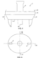
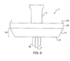
- the ship docking vessel 1 also may be optionally equipped with one or more cycloidal propulsion units 40, known in the art as a Voith-Schneider design, in lieu of the aforementioned Z-drives.
- cycloidal propulsion units 40 known in the art as a Voith-Schneider design
- This embodiment is illustrated in Figures 4-6. It will be understood that the features and advantages of the embodiment shown in Figures 1-3 will, likewise, be realized in the alternate embodiment of Figures 4-6.
- the flat bottom 12 of the vessel 1 of the present invention has a high beam-to-length ratio.
- the high ratio of beam to length decreases the draft of the hull 14 to as little as 3'6". This low draft facilitates maneuverability and operational capability, especially in shallow and confined areas.
- the Z-drives 8,10 are clear of any obstruction of the flow of water, thereby providing maximum thrust even when the vessel 1 is alongside another hull. This arrangement further provides faster response, improved stability, and improved maneuverability when the vessel 1 is running alone.
- the shape ofthe flat bottom 12 is symmetrical about the transverse and longitudinal axes 22, 20, having symmetrical curved ends fore and aft.
- the transverse opposite sides 16, 18 preferably have a parallel flat section, but, otherwise, the flat bottom 12 has a substantially elliptical shape.
- the curved hull shape and rounded ends facilitate maneuverability and the application of full force by the vessel in any direction. Additionally, the curved hull provides enhanced maneuverability about the front and angled portions of a vessel being towed to improve the guiding capability of the ship-docking vessel 1.
- the vessel 1 of the present invention provides many operational and design advantages over conventional ship-docking vessel designs.
- the hull of the vessel 1 is symmetrical, as described above, and has a preferably parallel midsection 16, 18. This hull configuration, coupled with the Z-drive and skeg arrangement of the instant invention, provides directional stability and maneuverability to the vessel.
- the bottom 12 ofthe vessel 1 is substantially flat and has a high beam-to-length ratio.
- a flat bottom having a high beam-to-length ratio reduces draft and improves speed in all directions, thereby improving performance. It has been found that a beam-to-length ratio of greater than 70% is preferred.
- the bottom 12 is joined directly to the hull, further simplifying construction by eliminating the need for bilge chines and reducing the need for curved plates.
- the high beam-to-length ratio also provides increased stability and reduces the amount of list and trim experienced when moving another vessel.
- the large flat-bottom, open-hull design also facilitates easy arrangement of equipment on the relatively large clear deck space. For example, winches, staples, chocks, and the like may be arranged in various configurations according to the requirements of the operator for efficient ship handling.
- the arrangement of the skegs 4, 6 and thrusters 8, 10, as described above, provides numerous operational advantages.
- Z-drives are adapted to extend below the hull, as with conventional Z-drives, but, due to the shallow hull configuration ofthe instant invention, these drives are clear of any obstructions of the flow of water. This arrangement provides maximum thrust, even when the ship-docking vessel 1 is alongside another hull, and provides quick response when the vessel 1 is running alone.
- the drives 8, 10 provide quick response, fast stopping, turning, and directional stability in any direction. Additionally, the arrangement allows the operator to apply full force in any direction, i.e., pushing, pulling, or "hipped-up" to another vessel. Moreover, the vessel 1 is equally well suited for movement in any direction, i.e., fore, aft, port, or starboard when running alone or in applying steering force to an assisted vessel.
Landscapes
- Engineering & Computer Science (AREA)
- Combustion & Propulsion (AREA)
- Mechanical Engineering (AREA)
- Ocean & Marine Engineering (AREA)
- Chemical & Material Sciences (AREA)
- Other Liquid Machine Or Engine Such As Wave Power Use (AREA)
- Filling Or Discharging Of Gas Storage Vessels (AREA)
- Toys (AREA)
- Pressure Vessels And Lids Thereof (AREA)
- Traffic Control Systems (AREA)
- Vibration Prevention Devices (AREA)
- Tires In General (AREA)
- Wind Motors (AREA)
- Transmission Devices (AREA)
- Vibration Dampers (AREA)
Applications Claiming Priority (2)
| Application Number | Priority Date | Filing Date | Title |
|---|---|---|---|
| US670784 | 1996-06-24 | ||
| US08/670,784 US5694877A (en) | 1996-06-24 | 1996-06-24 | Ship docking vessel |
Publications (2)
| Publication Number | Publication Date |
|---|---|
| EP0816218A2 true EP0816218A2 (de) | 1998-01-07 |
| EP0816218A3 EP0816218A3 (de) | 1999-06-16 |
Family
ID=24691859
Family Applications (1)
| Application Number | Title | Priority Date | Filing Date |
|---|---|---|---|
| EP97401311A Withdrawn EP0816218A3 (de) | 1996-06-24 | 1997-06-10 | Schiffsassistenzschlepper |
Country Status (15)
| Country | Link |
|---|---|
| US (1) | US5694877A (de) |
| EP (1) | EP0816218A3 (de) |
| JP (1) | JPH10100987A (de) |
| KR (1) | KR100249423B1 (de) |
| AR (1) | AR007468A1 (de) |
| AU (1) | AU2624597A (de) |
| BR (1) | BR9703691A (de) |
| CA (1) | CA2207347A1 (de) |
| IL (1) | IL121110A0 (de) |
| MX (1) | MX9704690A (de) |
| NO (1) | NO972926L (de) |
| RU (1) | RU2135387C1 (de) |
| SG (1) | SG50847A1 (de) |
| TR (1) | TR199700535A3 (de) |
| TW (1) | TW344729B (de) |
Cited By (1)
| Publication number | Priority date | Publication date | Assignee | Title |
|---|---|---|---|---|
| EP2193989A1 (de) * | 2008-12-05 | 2010-06-09 | Akira Nagayama | Schiff mit sechseckigem Unterbau zum Antreiben einer Schute |
Families Citing this family (10)
| Publication number | Priority date | Publication date | Assignee | Title |
|---|---|---|---|---|
| NL1012591C2 (nl) * | 1999-07-13 | 2001-01-16 | Scheepswerf Damen Gorinchem B | Sleepboot. |
| GB0019134D0 (en) * | 2000-08-04 | 2000-09-27 | Crossland Tankers Limited | A mixing device |
| DE10206669A1 (de) * | 2002-02-18 | 2003-08-28 | Siemens Ag | Linienentwurf und Propulsionsanordnung für ein kursstabiles, seegehendes Schiff mit Ruderpropellerantrieb |
| NL1022266C1 (nl) * | 2002-12-24 | 2004-06-25 | Novatug B V | Bedieningsinstallatie van een sleepinrichting op een sleepboot. |
| NL2008836C2 (en) | 2012-05-16 | 2013-11-20 | Sacar Holding Nv | Azimuth friction free towing point. |
| ITRM20120287A1 (it) * | 2012-06-20 | 2013-12-21 | Ugo Savona | Scafo perfezionato di un rimorchiatore e rimorchiatore comprendente detto scafo perfezionato. |
| KR101411508B1 (ko) | 2013-04-05 | 2014-06-24 | 삼성중공업 주식회사 | 동요제어장치 및 동요제어방법. |
| NL2014304B1 (en) * | 2015-02-17 | 2016-10-13 | Nova Patent B V | Tugboat provided with a carrousel-type towing system. |
| EP3356218A4 (de) * | 2015-10-01 | 2019-07-03 | Tow-Botic Systems Private Limited | Manövriervorrichtung und verfahren dafür |
| US11414169B2 (en) * | 2020-09-04 | 2022-08-16 | Mblh Marine, Llc | Asymmetrically shaped flanking rudders |
Family Cites Families (19)
| Publication number | Priority date | Publication date | Assignee | Title |
|---|---|---|---|---|
| US203940A (en) * | 1878-05-21 | Improvement in construction of ships | ||
| DE31874C (de) * | GEBRÜDER BENNINGER in Utzwyl, Kanton St. Gallen, Schweiz | Schlichtmaschine | ||
| US102111A (en) * | 1870-04-19 | Improvement in screw propulsion for tuo-boats | ||
| US2039399A (en) * | 1932-02-19 | 1936-05-05 | Englis John | Vessel |
| US2347077A (en) * | 1941-05-21 | 1944-04-18 | Weaver Associates Corp | Hull form |
| US2347785A (en) * | 1942-11-10 | 1944-05-02 | Earl V Lovell | Ship propulsion |
| US2837049A (en) * | 1948-11-25 | 1958-06-03 | J M Voith G M B H Maschinenfab | River ferry driven by two sail-wheel propellers |
| US3176645A (en) * | 1963-04-25 | 1965-04-06 | Shell Oil Co | Ship positioning apparatus |
| US3536025A (en) * | 1968-08-21 | 1970-10-27 | Leisure Ind | Motorized surfboard |
| US3750607A (en) * | 1971-06-23 | 1973-08-07 | D Seymour | Shallow-draft boat |
| US3895593A (en) * | 1973-09-24 | 1975-07-22 | Moore Alvin E | Light-weight, durable, water-traversing vehicle |
| NO136038C (no) * | 1975-06-18 | 1978-04-14 | Liaaen As A M | Propellanordning. |
| DE2655667C3 (de) * | 1976-12-08 | 1980-09-25 | Schottel-Werft Josef Becker Gmbh & Co Kg, 5401 Spay | Wasserfahrzeug |
| DE2809662C2 (de) * | 1978-03-07 | 1983-10-20 | Willi Becker Ingenieurbüro GmbH, 2000 Hamburg | Antrieb für Schiffe bestehend aus einer düsenartigen Ummantelung mit einem Propeller und einem zugeordneten Ruder |
| US4369725A (en) * | 1978-06-30 | 1983-01-25 | Mitsui Engineering & Shipbuilding Co., Ltd. | Method and means for increasing the maneuverability of a ship in ice-covered waters |
| SE8301196L (sv) * | 1983-03-04 | 1984-09-05 | Goetaverken Arendal Ab | Anordning vid farkoster med parallella skrov |
| US4928613A (en) * | 1988-11-09 | 1990-05-29 | Rudolf William B | Retractable steering device for cargo barges that increases maneuverability by providing a pivot point or points when altering course |
| US4998898A (en) * | 1989-03-31 | 1991-03-12 | Randy Dufrene | Ultralight/compact airboat apparatus |
| US5488918A (en) * | 1991-05-02 | 1996-02-06 | Fontain M. Johnson | Optimized barge bow form and methods of use thereof |
-
1996
- 1996-06-24 US US08/670,784 patent/US5694877A/en not_active Expired - Lifetime
-
1997
- 1997-06-09 CA CA002207347A patent/CA2207347A1/en not_active Abandoned
- 1997-06-10 EP EP97401311A patent/EP0816218A3/de not_active Withdrawn
- 1997-06-13 SG SG1997002050A patent/SG50847A1/en unknown
- 1997-06-19 IL IL12111097A patent/IL121110A0/xx unknown
- 1997-06-23 NO NO972926A patent/NO972926L/no unknown
- 1997-06-23 MX MX9704690A patent/MX9704690A/es not_active Application Discontinuation
- 1997-06-23 KR KR1019970026604A patent/KR100249423B1/ko not_active Expired - Fee Related
- 1997-06-23 RU RU97110129A patent/RU2135387C1/ru active
- 1997-06-24 BR BR9703691-9A patent/BR9703691A/pt not_active Application Discontinuation
- 1997-06-24 AR ARP970102773A patent/AR007468A1/es unknown
- 1997-06-24 AU AU26245/97A patent/AU2624597A/en not_active Abandoned
- 1997-06-24 TW TW086108836A patent/TW344729B/zh active
- 1997-06-24 TR TR97/00535A patent/TR199700535A3/tr unknown
- 1997-06-24 JP JP9167035A patent/JPH10100987A/ja active Pending
Non-Patent Citations (1)
| Title |
|---|
| None |
Cited By (1)
| Publication number | Priority date | Publication date | Assignee | Title |
|---|---|---|---|---|
| EP2193989A1 (de) * | 2008-12-05 | 2010-06-09 | Akira Nagayama | Schiff mit sechseckigem Unterbau zum Antreiben einer Schute |
Also Published As
| Publication number | Publication date |
|---|---|
| US5694877A (en) | 1997-12-09 |
| IL121110A0 (en) | 1997-11-20 |
| SG50847A1 (en) | 1998-07-20 |
| JPH10100987A (ja) | 1998-04-21 |
| TR199700535A2 (xx) | 1998-01-21 |
| TW344729B (en) | 1998-11-11 |
| TR199700535A3 (tr) | 1998-01-21 |
| CA2207347A1 (en) | 1997-12-24 |
| AR007468A1 (es) | 1999-10-27 |
| KR980001703A (ko) | 1998-03-30 |
| KR100249423B1 (ko) | 2000-04-01 |
| RU2135387C1 (ru) | 1999-08-27 |
| NO972926L (no) | 1997-12-29 |
| AU2624597A (en) | 1998-01-15 |
| BR9703691A (pt) | 2000-12-19 |
| EP0816218A3 (de) | 1999-06-16 |
| MX9704690A (es) | 1997-12-31 |
| NO972926D0 (no) | 1997-06-23 |
Similar Documents
| Publication | Publication Date | Title |
|---|---|---|
| US6698374B1 (en) | Design for tugboat | |
| AU2005291367B2 (en) | An improved convertible vessel | |
| US3750607A (en) | Shallow-draft boat | |
| US5694877A (en) | Ship docking vessel | |
| JP2006516511A (ja) | 船舶用操舵及び推進構造 | |
| US20020134290A1 (en) | Landing craft with fixed and retractable azimuthing drives | |
| EP2371701A1 (de) | Schiff, wie etwa ein Schlepper, mit Azimut-Antrieb | |
| US3561388A (en) | Hydrofoil saling craft | |
| US7721665B2 (en) | Hull and steering mechanism for a marine vessel | |
| USRE28615E (en) | Hydrofoil sailing craft | |
| US2902966A (en) | Tugboat and towing system comprising the same | |
| WO2004020276A1 (en) | Vessel provided with a foil situated below the waterline | |
| AU2021226803B2 (en) | A vessel | |
| NL1012591C2 (nl) | Sleepboot. | |
| EP2193989A1 (de) | Schiff mit sechseckigem Unterbau zum Antreiben einer Schute | |
| RU217176U1 (ru) | Корпус судна-буксира | |
| RU222507U1 (ru) | Корпус судна-буксира | |
| EP1253074B1 (de) | Schlepper | |
| EP2250078A2 (de) | Seefahrzeug mit beweglichem kiel | |
| US3509844A (en) | Power steering for ships and boats | |
| Van der Laan | Carrousel tug design | |
| Keuning | Motion Control for Small Fast Boats in Following Seas | |
| Taggart | A Unique Tug Design for Deepwater Terminal Service |
Legal Events
| Date | Code | Title | Description |
|---|---|---|---|
| PUAI | Public reference made under article 153(3) epc to a published international application that has entered the european phase |
Free format text: ORIGINAL CODE: 0009012 |
|
| AK | Designated contracting states |
Kind code of ref document: A2 Designated state(s): DE DK ES FI FR GB IT NL SE |
|
| PUAL | Search report despatched |
Free format text: ORIGINAL CODE: 0009013 |
|
| AK | Designated contracting states |
Kind code of ref document: A3 Designated state(s): AT BE CH DE DK ES FI FR GB GR IE IT LI LU MC NL PT SE |
|
| 17P | Request for examination filed |
Effective date: 19990730 |
|
| AKX | Designation fees paid |
Free format text: DE DK ES FI FR GB IT NL SE |
|
| 17Q | First examination report despatched |
Effective date: 20000728 |
|
| STAA | Information on the status of an ep patent application or granted ep patent |
Free format text: STATUS: THE APPLICATION IS DEEMED TO BE WITHDRAWN |
|
| 18D | Application deemed to be withdrawn |
Effective date: 20001208 |