EP0816228B1 - Vorrichtung und Verfahren zum Herstellen von mit schüttfähigem Material gefüllten Verpackungspolsterkissen - Google Patents
Vorrichtung und Verfahren zum Herstellen von mit schüttfähigem Material gefüllten Verpackungspolsterkissen Download PDFInfo
- Publication number
- EP0816228B1 EP0816228B1 EP19970304660 EP97304660A EP0816228B1 EP 0816228 B1 EP0816228 B1 EP 0816228B1 EP 19970304660 EP19970304660 EP 19970304660 EP 97304660 A EP97304660 A EP 97304660A EP 0816228 B1 EP0816228 B1 EP 0816228B1
- Authority
- EP
- European Patent Office
- Prior art keywords
- tubing
- core
- loose fill
- tape
- hubs
- Prior art date
- Legal status (The legal status is an assumption and is not a legal conclusion. Google has not performed a legal analysis and makes no representation as to the accuracy of the status listed.)
- Expired - Lifetime
Links
Images





Classifications
-
- B—PERFORMING OPERATIONS; TRANSPORTING
- B65—CONVEYING; PACKING; STORING; HANDLING THIN OR FILAMENTARY MATERIAL
- B65D—CONTAINERS FOR STORAGE OR TRANSPORT OF ARTICLES OR MATERIALS, e.g. BAGS, BARRELS, BOTTLES, BOXES, CANS, CARTONS, CRATES, DRUMS, JARS, TANKS, HOPPERS, FORWARDING CONTAINERS; ACCESSORIES, CLOSURES, OR FITTINGS THEREFOR; PACKAGING ELEMENTS; PACKAGES
- B65D81/00—Containers, packaging elements, or packages, for contents presenting particular transport or storage problems, or adapted to be used for non-packaging purposes after removal of contents
- B65D81/02—Containers, packaging elements, or packages, for contents presenting particular transport or storage problems, or adapted to be used for non-packaging purposes after removal of contents specially adapted to protect contents from mechanical damage
- B65D81/05—Containers, packaging elements, or packages, for contents presenting particular transport or storage problems, or adapted to be used for non-packaging purposes after removal of contents specially adapted to protect contents from mechanical damage maintaining contents at spaced relation from package walls, or from other contents
- B65D81/051—Containers, packaging elements, or packages, for contents presenting particular transport or storage problems, or adapted to be used for non-packaging purposes after removal of contents specially adapted to protect contents from mechanical damage maintaining contents at spaced relation from package walls, or from other contents using pillow-like elements filled with cushioning material, e.g. elastic foam, fabric
-
- B—PERFORMING OPERATIONS; TRANSPORTING
- B65—CONVEYING; PACKING; STORING; HANDLING THIN OR FILAMENTARY MATERIAL
- B65B—MACHINES, APPARATUS OR DEVICES FOR, OR METHODS OF, PACKAGING ARTICLES OR MATERIALS; UNPACKING
- B65B67/00—Apparatus or devices facilitating manual packaging operations; Sack holders
- B65B67/02—Packaging of articles or materials in containers
- B65B67/06—Manually-operable devices for closing bag necks, by applying and securing lengths of string, wire or tape
-
- B—PERFORMING OPERATIONS; TRANSPORTING
- B65—CONVEYING; PACKING; STORING; HANDLING THIN OR FILAMENTARY MATERIAL
- B65B—MACHINES, APPARATUS OR DEVICES FOR, OR METHODS OF, PACKAGING ARTICLES OR MATERIALS; UNPACKING
- B65B9/00—Enclosing successive articles, or quantities of material, e.g. liquids or semiliquids, in flat, folded, or tubular webs of flexible sheet material; Subdividing filled flexible tubes to form packages
- B65B9/10—Enclosing successive articles, or quantities of material, in preformed tubular webs, or in webs formed into tubes around filling nozzles, e.g. extruded tubular webs
- B65B9/15—Enclosing successive articles, or quantities of material, in preformed tubular webs, or in webs formed into tubes around filling nozzles, e.g. extruded tubular webs the preformed tubular webs being stored on filling nozzles
-
- B—PERFORMING OPERATIONS; TRANSPORTING
- B65—CONVEYING; PACKING; STORING; HANDLING THIN OR FILAMENTARY MATERIAL
- B65H—HANDLING THIN OR FILAMENTARY MATERIAL, e.g. SHEETS, WEBS, CABLES
- B65H35/00—Delivering articles from cutting or line-perforating machines; Article or web delivery apparatus incorporating cutting or line-perforating devices, e.g. adhesive tape dispensers
- B65H35/0006—Article or web delivery apparatus incorporating cutting or line-perforating devices
Definitions
- This invention pertains generally to apparatus for packaging loose fill packing material in bags for use as protective cushions in shipping cartons and, more particularly, to a bag sealer and cutter for use in such systems.
- Loose fill packing materials are commonly poured into cartons so as to surround and embrace articles and thereby cushion them during shipment. Such materials are typically fabricated of a variety of materials such as foamed plastics, starch and other biodegradable materials.
- GB 1 564 397 discloses a common packaging machine used for packaging articles such as fruit or vegetables.
- the present invention provides a method of filling cushions using a loose fill cushion packing apparatus, wherein the apparatus comprises a hopper for the storage of loose fill packing material which has an end for the discharge of loose fill material, the apparatus further comprising means for actuating the apparatus to dispense loose fill packing material from the hopper; a length of flexible tubing gathered axially and disposed coaxially of the hopper discharge end such that successive sections of the tubing can be drawn, filled with loose fill material and closed to form cushions; means for closing off successive sections of tubing to form the cushions from the filled bags, the means adapted to apply two axially spaced apart closing bands to the tubing to simultaneously close a first end of a first tube section and provide a closed end for a second successive tube section; and means for cutting the tubing between the two closing bands to sever successive tube sections; wherein the method comprises the steps of actuating the apparatus using means to dispense loose fill material into a first section of the tubing, simultaneously closing the first and a second successive section of tubing by applying
- the invention provides a combination of loose fill cushion packing material and a loose fill material cushion packing apparatus, the apparatus comprising a hopper containing loose fill packing material and having an end for the discharge of loose fill material; means for actuating the apparatus to dispense the loose fill packing material from the hopper; a length of flexible tubing gathered axially and disposed coaxially of the hopper discharge end such that successive sections of the tubing can be drawn, filled with loose fill material and closed to form cushions; and wherein the apparatus has means for closing off successive sections of tubing to form the cushions from the filled bags, the means adapted to apply two axially spaced apart closing bands to the tubing to simultaneously close a first end of a first tube section and provide a closed end for a second successive tube section; and means for cutting the tubing between the two closing bands to sever successive tube sections.
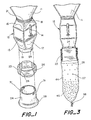
- the system includes a hopper 11 for holding a supply of loose fill packing material, with a valve 12 at the lower end of the hopper for dispensing the material from the hopper.
- the valve can, for example, be of the type disclosed in U.S. Patent 4,844,291. It has a generally rectangular body 13 with a pair of hinged flaps (not shown) connected to an operator 14 for controlling the flow of material through the valve.
- the valve has transition pieces 16, 17 on its inlet and outlet sides, with circular collars 18, 19 at the outer ends thereof.
- Hopper 11 comprises a tapered bag fabricated of a flexible plastic material such as polyethylene which is suspended from the ceiling or other suitable support.
- the upper end of the hopper bag is open, and the lower end is secured to the circular collar on the upper, or inlet, side of the valve by a band clamp 21.
- a length of flexible plastic tubing 23 is stored on a coil holder 24 mounted on collar 19 for use in the formation of bags for holding loose fill material dispensed through the valve.
- the tubing is folded and gathered in an axial direction to form a coil which is held together by suitable means such as paper tape or ties 26 until it is mounted on the coil holder.
- the tubing can be fabricated of any suitable material such as polyethylene, and can be of any desired weight.
- a polyethylene tubing having a wall thickness of 12.7 X 10 -6 m (0.5 mil) has been found to provide good strength and flexibility for the bags, and with a 12.7 X 10 -6 m (0.5 mil) material, a coil can contain several hundred feet of tubing.
- Other suitable material include high density polyethylene, low density polyethylene, netting, and cellulose (paper) products.
- vent holes 27 which serve to prevent air from being trapped within the tubing as the side walls are drawn together to form the cushions.
- the holes can be of any suitable size and spacing, and in one presently preferred embodiment, they are on the order of 12.7mm (1 ⁇ 2 inch) in diameter and spaced on centers about 76-127mm (3-5 inches) apart.
- the lower end 28 of the coil holder is enlarged to retain the coil on the coil holder.
- the tubing is withdrawn from the coil holder by pulling it down over the_enlarged end, with the outer diameter of the enlarged end being slightly larger than the unstretched tubing so that the tubing will remain in place unless it is pulled.
- the enlarged end is shown as a flare. However, it can be formed in any other suitable manner such as by slotting the end portion of the cylindrical side wall and bending the tabs thus formed between the slots in an outward direction or by attaching a plurality of outwardly projecting tabs to the side wall.
- the coil holder is removably mounted on outlet collar 19 by means of a bayonet mount comprising a pair of pins 29 which extend radially from the collar and are received in J-shaped slots 31 in the upper end of the cylindrical side wall of the coil holder.
- the system also includes a tool 33 for cutting the tubing into bag-length sections and the closing bags thus formed.
- This tool includes a pair of tape dispensers 34, 36 which apply bands of tape 37, 38 to the tubing after it has been drawn together, and a cutting blade or knife 39 which cuts the two sections of tubing apart between the bands of tape.
- Suitable tape dispensers are available commercially, and include the Jokari Model 05505 bag sealer and the Excell® EG Cut Bag Sealer, Model No. 605K.
- Each of the tape dispensers has a vertically extending guide slot 41 through which the gathered walls of the tubing are drawn to trigger the application of the tape.
- the blade is positioned toward the lower ends of the guide slots and inclined at an angle of about 45° to the slots for slicing the tubing material immediately after it passes the point where the tape is applied.
- the taping and cutting tool is positioned below and to one side of the outlet of the dispenser, within reach of the lower end of a bag which is still hanging from the coil holder.
- the tool can be mounted on a stand or other suitable support.
- the closed ends of the tubing sections or bags can be secured with means other than tape strips.
- suitable means include metal clips, heat sealing, wire ties, plastic ties, string, and the like.
- the loose fill material can be any material which is suitable for use in the cushions. Suitable materials include, but are not limited to, polystyrene, starch-based materials, paper and popcorn. It is also possible to use brittle and flaky materials which ordinarily are not suitable for use as packing materials. It is also possible to use combinations of different materials, and since they are enclosed within the bags, they will not be unsightly.
- Loose fill material is introduced into the hopper from above by suitable means such as a pneumatic conveyor (not shown) or by lowering the hopper bag and pouring the material into it.
- Coil holder 24 is removed from the dispenser, and a coil of tubing 23 is placed on it. The coil holder is reattached to outlet collar 19, and the ties 26 which hold the coil together are removed.
- a first section of tubing 44 is withdrawn from the coil by pulling it down over the enlarged lower end 28 of the coil holder, and the lower end of that section is drawn together and taped to form a bag which hangs from the dispenser, as illustrated in Figure 3.
- the valve is then opened to discharge a predetermined amount of the loose fill material 46 into the bag.
- a second section of tubing 47 is withdrawn from the coil, and the portion of the tubing between the two sections is drawn together and passed through taping and cutting tool 33.
- bands of tape 37, 38 are applied simultaneously to the upper end of section 44 and to the lower end of section 47 to secure those ends in the closed position.
- the downward motion of the tubing then brings it into contact with blade 39 which severs the tubing between the two bands of tape, thereby separating the filled bag or cushion 49 formed by section 44 from section 47.
- a finished cushion is illustrated in Figure 6. As discussed more fully hereinafter, it is used by placing it and other cushions like it about an article in a carton. With the loose fill material enclosed in the cushion, there is no spillage of material during the packaging process.
- the cushions are simply removed from the carton as needed to provide access to the articles.
- the cushions remain intact, with the loose fill material fully contained within them, and they can be recycled, reused, or disposed of, as desired.
- FIG. 7 in conjunction with the packaging of an article 51 in a carton or container 52 which has a removable lid or top 53.
- the article is illustrated as being in the form of a bottle, but it can be anything that needs to be protectively packaged.
- the container is illustrated as being a cardboard box, but it can be any container which is suitable for packaging or shipping the article.
- the lid can be secured to the container by any suitable means such as taping or stapling.
- the tubing from which the bags are formed is unvented (i.e., without vent holes 27), and after the bags are closed, air and/or other gases or fluids are withdrawn from them to reduce the pressure within them to a level below that of the surrounding environment, e.g . below atmospheric pressure. That is conveniently done by piercing each bag with a lance or needle connected to a vacuum pump. The difference in the air pressures inside and outside the bags compresses the fill material until the resilient force of the material counterbalances the compressive force applied by the pressure differential. The interiors of the cushions are thereafter repressurized to reexpand the fill material to conform to contours of the article and the interior walls of the container. The cushions can be re-expanded and used immediately after compression, or they can be sealed for storage and/or shipment in the compressed state.
- recyclable, biodegradable, and/or water-soluble materials can be used either for the tubing or for the fill material, or both.
- suitable recyclable materials include Saran, ethylene vinyl acetate (EVA), polyethylene film, paper, and the like.
- Suitable water-soluble materials include polyvinyl alcohol (PVOH) based materials, and hydrocarbon based alloys, such as the Enviroplastic®-H based on polyoxyethylene, for example.
- Suitable biodegradable materials include water-soluble polyvinyl alcohol (PVOH) based films; poly-caprolactone-alphatic ester based materials; polyhydroxybutyrate-valerate (PHBV) copolymers; polyoxyethylene based materials; polyester based compostable material; starch based biopolymer materials; and other starch based materials such as those that include a catalyst to enhance photo and oxidative degradation.
- suitable recyclable materials include extruded polystyrene (EPS) beads and other materials which are neither biodegradable nor water soluble.
- EPS polystyrene
- Suitable biodegradable materials include starch graft copolymer materials, starch biopolymer materials, wood chips and shavings, plant fibers, twigs, seeds, popcorn, and the like.
- Suitable water soluble materials include starch based materials and other water soluble materials. Where vented tubing is used for the bags, the particles of fill material should, of course, be larger than the vent openings to prevent spillage from the bags.
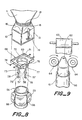
- Figure 8 illustrates an embodiment in which the tubing 23 is gathered or bunched onto a cylindrical core 56 that is mounted on a plurality of flexible fingers 57, 58 at the outlet side of dispensing valve 12.
- the core is fabricated of a relatively stiff material such as cardboard and has a diameter on the order of 152 to 178mm (6 to 7) inches and a length on the order of 305 to 356 mm (12 to 14 inches).
- the tubing is gathered or bunched onto the core by means of a machine 59 which is illustrated somewhat schematically in Figure 9. That machine has an upstanding mandrel 61 on which the core is mounted. The upper end 62 of the mandrel is tapered, and the tubing is fed onto the mandrel over the tapered end from a supply roll 63. A plurality of motorized rollers 64 at the base of the taper feed the tubing onto the core where it is gathered or bunched and secured by paper tape or ties 66.
- a machine of this type is available commercially from Newtec USA, Inc., Butler, Pennsylvania (Model NS 57-A automatic sleeving machine).
- Fingers 57, 58 are arranged in two pairs which are disposed in quadrature about the outlet of the valve. They are mounted on a transition piece 68 which consists of a rectangular base plate 69 with a circular opening 71, peripheral mounting flanges 72 which extend in an upward direction from the edges of the base plate, and a circular collar 73 which surrounds opening 71 and depends from the plate. Flanges 72 fit over the lower portion of valve body 13 and are secured to the valve body by mounting screws 74, with a cut-out 76 in one of the flanges providing clearance for valve actuator 14. The fingers are attached to the collar by suitable means such as rivets 77.
- the fingers are formed of a resilient material such as sheet metal, and are biased toward a retracted or rest position in which they extend downwardly and inwardly from the mounting collar. As discussed more fully hereinafter, the fingers can be spread apart for engagement with the core but return to their retracted or rest position when the core is removed.
- Means is provided at the lower ends of fingers 57, 58 for retaining core 56 on the fingers and the tubing 23 on the core.
- the fingers are formed from strips of sheet metal, and the lower portions of the strips are bent outwardly and upwardly to form hooks 78, 79 which retain the core and tubing.
- the hooks on the two pairs of fingers are generally similar in shape and in lateral dimension, but different in vertical dimension. This enables the core to be engaged with and disengaged from the hooks in the two pairs at different times, which makes it easier for one person to install and remove the core.
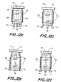
- each of the hooks has a horizontally extending section 81 at the lowermost end of the finger, a semi-cylindrical side section 82 which extends upwardly from the outer end of lower section 81, and a horizontal section 83 which extends in an inward direction from the upper end of the side section.
- the upper section terminates a short distance from the finger to form an opening or gap 84 through which the lower portion of core 56 can pass.
- the end portion 86 of the strip is folded under to provide a smooth edge at the opening.
- fingers 57, 58 are all of equal length 422mm (16-5/8 inches), and hooks 79 are 12.7mm (1 ⁇ 2 inch) taller than hooks 78.
- hooks 78 lower section 81 is 19.1mm (3/4 inch)long, side section 82 has a 12.7mm (1 ⁇ 2 inch) radius of curvature, and upper section 83 is 12.7mm (1 ⁇ 2 inch) Iong.
- lower section 81 is 11.1mm (7/16 inch) long
- side section 82 has a 19.1mm (3/4 inch) radius of curvature
- upper section 83 is 4.8mm (3/16 inch) long.
- the gap 84 between the finger and the inner end of upper section 83 is 6.4mm (1/4 inch).
- the lower sections of all four of the hooks lie in the same horizontal plane, and the lower edge of the core 56 rests upon the upper surfaces of those sections.
- the diameter of collar 73 is slightly less than that of the core, and when the core is mounted on the fingers and engaged with the hooks, fingers 57, 58 extend longitudinally within the core near the inner surface of the cylindrical side wall, with hooks 78, 79 projecting laterally beyond the core and the curved side sections of the hooks engaging the inside of the tubing at the lower end of the core. That engagement permits successive sections of the tubing to be pulled axially from the core while the remainder of the tubing remains in place on the core.
- the core is installed by positioning it beneath the discharge opening of the valve and lifting onto the fingers to a level such that the bottom edge of the core is above all four of the hooks.
- the lower ends of the fingers with the larger hooks, i.e . fingers 58, are then spread apart, and the core is lowered into those hooks, i.e . hooks 79.
- the operator can release it, and those hooks will hold it in place.
- the core is raised until its lower edge clears the tops of those hooks and fingers 57 can be spread to position the openings in the hooks beneath the wall of the core.
- hooks 79 are taller than hooks 78, the lower portion of the core will remain within hooks 79 while the fingers carrying hooks 78 are being spread. The core is then lowered into the four hooks, with the lower edge of the core resting upon hook sections 81.
- the ties are removed, and successive lengths of tubing are withdrawn, filled, closed and severed to form the cushions as in the embodiment of Figure 1.
- the outer surfaces of the hooks engage the inside of the tubing passing over them, allowing successive sections of the tubing to be pulled off the core while retaining the remainder of the tubing on the core.
- the core is removed by lifting it until the lower edge of the core is above the upper portions of all four hooks. With the hooks disengaged from the core, fingers retract to their rest position, and the core can drop freely over them.
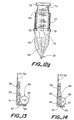
- Figures 13 and 14 illustrate embodiments similar to the embodiment of Figure 8, with different means at the lower ends of the fingers for retaining the core on the fingers and the tubing on the core.
- the lower portions of fingers 57, 58 are bent in an outward direction to form flanges 87 upon which blocks 88 are mounted to form hooks or holders for retaining the core and the on the fingers and the tubing on the core.
- the blocks are secured to the flanges by suitable means such as screws 89, with the outer portions of the blocks projecting laterally beyond the outer ends of the fingers.
- blocks 88 consist of lengths of solid rod 91 of circular cross-section which are oriented with the axis of the rod parallel to the plane of finger on which it is mounted. These blocks have a cylindrical side wall 92, the innermost portion of which is spaced from the outer surface of the finger to form an opening 93 for receiving the lower portion of the core.
- the outer portion of the side wall engages the inside of the tubing and prevents the tubing from dropping off the core.
- blocks 88 consist of lengths of solid rod 94 of semicircular cross-section which are oriented with the axis of the rod parallel to the plane of finger on which it is mounted. These blocks have a planar inner side wall 96 and a semi-cylindrical outer side wall 97, with inner wall being spaced from the outer surface of the finger to form an opening 98 for receiving the lower portion of the core.
- the semi-cylindrical side wall engages the inside of the tubing and prevents the tubing from falling off the core.
- the loose fill material can be dispensed directly into a carton in the embodiments of Figures 8-14 simply by removing the core from the fingers and placing the carton beneath the outlet of the valve.
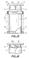
- the embodiment of Figure 15 is generally similar to the embodiment of Figure 8, and like reference numerals designate corresponding elements in the two embodiments.
- the embodiment of Figure 15 differs from the embodiment of Figure 8 in that it has only one pair of fingers 57 with hooks 78 for mounting core 56 to dispensing valve 12. Those fingers are disposed on diametrically opposed sides of the discharge opening in the valve.
- a horizontally extending annular ring 99 is positioned over the lower portion of the core and rests upon the upper sides of hooks 78.
- the ring is fabricated of a relatively rigid material such as sheet metal or plastic, with an inner diameter slightly larger than the core and an outer diameter slightly smaller than tubing 23.
- the tubing passes over the ring, with the ring engaging the inside of the tubing to permit successive sections to be withdrawn from the core while retaining the remainder of the tubing on the core.
- the ring also prevents the tubing from becoming caught between the core and the hooks, as might sometimes happen without the ring.
- the hooks or retainers are not required to control the removal of tubing from the core, and the core can be mounted on the dispenser with only two hooks instead of four. With only two fingers to manipulate and two hooks to engage, it is much easier for one person to install the core on the fingers. While the ring has been described with specific reference to hooks of the type shown in Figures 8 and 10, it can be utilized with any other suitable types of hooks, including the ones shown in Figures 13 and 14.
- means is also provided for preventing the core from being accidentally dislodged from the fingers, as might otherwise happen if the core were bumped in an upward direction or otherwise knocked out of the hooks.
- That means comprises a latch block 100 which is pivotally mounted on collar 73.
- a shoulder bolt 100a serves as a pivot, but any other suitable type of pivot pin can be used, if desired.
- the latch block is elongated, with the pivot pin positioned toward the upper end of the block so that the block normally hangs down in an extended or locking position. In that position, the lower end of the latch block serves as a limiting abutment for the upper edge of the core, which prevents the core from being lifted out of the hooks.
- the latch block can be swung to a retracted position by lifting the core against the block and turning the core horizontally about its axis. As the core turns with its upper edge in contact with the block, the block pivots in an upward direction, allowing the core to move up and away from the hooks. When the core is lowered, the block drops back to its vertical position.
- the tubing is installed by placing ring 99 over the lower portion of core 56 between the tubing and the end of the core, lifting the core onto fingers 57, and turning the core as it engages latch block 100 to move the block out of the blocking position.
- the fingers are spread apart, and the core is lowered into the hooks, with the ring resting on the upper sides of the hooks.
- the latch block falls back to its vertical or locking position where it prevents the core from being dislodged from the hooks.
- the lower portion of the tubing is drawn over the ring, and successive sections of the tubing can then be withdrawn from the core and filled with the loose fill material as in the other embodiments.
- the core is removed by lifting it against the latch block and turning the core to swing the block out of the way.
- resilient fingers 57 return to their retracted or rest position, and the core and the ring drop freely off them, with the latch block returning to its vertical position.
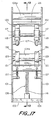
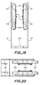
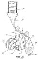
- Figures 17-21 illustrate a bag sealer and cutter which is particularly suitable for use in this system for closing end portions of the tubing to form the bags and severing one section of the tubing from the next as the bags are filled and sealed.
- This tool has a pair of spaced apart side plates 101 affixed to a base 102 by screws 103, with spacers 104a-104c extending between the plates above the base.
- the base is adapted to be mounted on a suitable support such as a tool post (not shown) below and to one side of the dispenser outlet.
- Aligned slots 106 in the side plates define a path for the tubing, and the mouth 106a of the slots is tapered to assist in drawing the tubing together between successive sections to form the bags.
- Two rolls 107 of sealing tape are rotatively mounted between the plates on one side of the path for application to the tubing to seal the bags.
- Each of the rolls is mounted on a holder which has a cylindrical hub 108 that extends through the opening in the core of the tape roll.
- the outer ends of the hubs are affixed to the side plates, and the tape roll is retained on each of the hubs by a keeper plate or key 109 which is removably mounted in a vertically extending slot 110 toward the inner end of the hub.
- the slot is formed in the inner face of the hub and closed by a circular cover 111 which is screwed onto the inner face.
- the keeper plate or key has an enlarged head 112 which prevents it from passing all the way through the slot when inserted into it from above.
- Means for providing controlled resistance to rotation of the tape rolls on the hubs. That means includes a ball plunger 113 which is mounted in a diametrically extending threaded bore 114 in each of the hubs.
- the plunger includes a ball 116 which is urged against the inner face of the tape roll core by an internal coil spring (not shown). Rotation of the tape roll is resisted by a combination of the drag of the ball on the core and friction between the core and the surface of the hub on the side of the hub opposite the plunger.
- the amount of force with which the ball engages the core can be adjusted by turning the plunger with a screwdriver inserted into the bore from the back side of the plunger to change the position of the plunger within the bore.
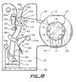
- Tape from the rolls is applied to the tubing by a pair of star wheels 117 which are affixed to an axle 118 for rotation in concert about an axis 119 which is generally perpendicular to the path defined by the slots.
- the star wheels have radial fingers or teeth 121 which extend across the path and are engaged in driving relationship by the tubing travelling along the path and through the wheels.
- Arcuately curved leaf springs 122 are disposed peripherally of the star wheels on the other side of the slots to keep the tubing in the openings 123 between the teeth and to help in the application of the tape to the tubing.
- the star wheels each have six teeth, and the leaf springs have an arc length somewhat greater than 60° so that they span the distance between adjacent pairs of the teeth.
- the leaf springs are mounted on a bar 126 which extends between the side plates. Stops 127 are mounted on side plates 101 toward the lower ends of the springs to limit outward travel of the springs and prevent them from being deflected too far away from the outer ends of the teeth on the star wheels.
- the star wheels have a rest position in which one of the teeth 121a on each wheel extends in an upward direction in alignment with one edge of the path and the tooth 121b adjacent to it extends across the path, with the path leading into the space 123a between these teeth.
- the tape 129 from rolls is trained about the outer ends of teeth 121a, 121b and extends along the inner faces of the leaf springs, with the outer ends of the teeth being notched for the tape.
- the sticky side of the tape faces up and adheres to the faces of the springs.
- the tape is depressed into the opening 123a ahead of the tape, and more tape is drawn from the rolls.
- the wheels turn in a downward direction, and the tape is peeled off the faces of the springs and wrapped in bands about the tubing.
- a pair of cutters 129 are mounted beneath the star wheels for cutting the tape leading from the leaf springs to the tubing after the bands of tape have been applied.
- the cutters are affixed to a shaft 131 for movement in concert about a pivot axis 132.
- Each of the cutters has a first arm 133 which carries a cutting blade 134, and a second arm 136 which extends across the path of the tubing when the cutters are in a rest position.
- Springs 137 bias the cutters toward the rest position, with arms 136 abutting against spacer 104b in that position. Since the tape is trained about the star wheels, those wheels continue to turn until the tape is cut, and the position of the cutters is such that the star wheels will be left in their rest position when the cuts are made.
- a knife 138 is mounted on base 102 toward the lower end of the slots for severing the tubing between the sections after the bands of tape have been applied.
- the knife consists of a blade 139 mounted in a holder 141 affixed to the base.
- the blade lies in a plane which is midway between side plates 101 and parallel to them, with the blade being inclined downwardly and rearwardly at an angle on the order of 45° to provide a slicing action as the tubing moves past it.
- the tubing As the tubing travels down the slot, it turns star wheels 117, causing them to apply two bands of tape to the gathered tubing to simultaneously seal the upper end of the bag which has just been filled and the lower end of the bag which is being formed from the next section of the tubing.
- the tubing engages cutter arms 136, the cutters pivot, and blades 134 cut the tape just above the bands.
- the tubing then engages knife blade and is severed between the bands, leaving one bag which has been filled and sealed at both ends and one which has been sealed at one end and is ready to be filled.
- Figures 22 and 23 illustrate an embodiment in which the tubing 23 is gathered together about a fixed mandrel, bands of tape 151 are wrapped about the gathered tubing to hold it in a bundle 152, and the bundle is then removed from the mandrel and flattened for storage and shipment.
- a band of strapping material 153 is wrapped longitudinally about the bundle parallel to bands 151 to hold it in its flattened or compacted state. If desired, a plurality of flattened bundles (e.g ., six bundles) can be stacked together and secured with a single strap.
- a 122m (400 foot) length of tubing which is gathered onto a core which is 177,8 mm (seven inches) in diameter and 381 mm (15 inches) long typically has an outside diameter on the order of 279 mm and requires a volume of approximately 23352 cm 3 (1425 cubic inches).
- that same bundle occupies a space approximately 0.33m (13 inches) long, 0.31 m (12 inches) wide and 0.1 m (4 inches) high, with a volume of approximately 10242cm 3 (625 cubic inches).
- Bands 151 are relatively wide so that they will remain in place when the bundle is flattened. In the embodiment illustrated, four bands are employed, and they are spaced in quadrature about the bundle. For a bundle formed on a seven inch mandrel, each band has a width on the order of three inches. These bands are formed of a material such as paper or plastic tape with reinforcing filaments, and the ends of the bands are secured together by suitable means such as staples or and an adhesive.
- Figures 24 and 25 illustrate a collapsible core 156 which can be utilized to mount bundles 152 on the dispenser.
- Core 156 has a cylindrical side wall 157 which is formed in three sections 158-160 that are disposed side-by-side and hinged together along longitudinally extending lines 162-164 between the sections.
- the wall sections are fabricated of sheet metal, plastic or another suitable semi-rigid material, and they are connected together by hinges 166-168.
- Wall section 158 has an arc length on the order of 270° to 300° and sections 159, 160 each have an arc length on the order of 30° to 45°.
- the core In its normal state, shown in solid lines in Figure 25, the core is in the form of a right circular cylinder which has a diameter corresponding to that of the core or mandrel on which bundles 152 are formed.
- wall sections 159, 160 In the collapsed state, which is shown in dashed lines in Figure 25, wall sections 159, 160 extend in an inward direction, and the diameter of the cylinder is reduced. Since the spacing between the edges of wall section 158 is less than the combined chord lengths of wall sections 159, 160, section 158 must flex and its edges must separate somewhat as sections 159, 160 are swung between their extended and collapsed positions.
- the material which forms section 158 has a memory which causes that section to tend to return to its normal shape.
- the wall sections thus function as an over-center mechanism, with the force produced by the memory of section 158 biasing the two shorter sections toward their extended and collapsed positions.
- core 156 is collapsed by pressing inwardly on wall sections 159, 160.
- the collapsed core is then inserted into a bundle of tubing from which the band 153 has been removed and expanded by pressing outwardly on sections 159, 160.
- bands 151 are removed, and the core is mounted on the loose fill dispenser in the same manner that core 56 is mounted in the embodiments discussed above, e.g . by mounting it on fingers 57 in the embodiment shown in Figure 15.
- ring 99 is placed over the lower portion of the core, and the tubing passes over the ring as it is withdrawn from the core, with latch block 100 preventing the core from being inadvertently lifted and dislodged from the hooks at the lower ends of the fingers.
- Figure 26 illustrates an embodiment in which a collapsible core 171 is fabricated of a material such as cardboard or plastic, with wall sections 172-174 corresponding to the wall sections 158-160 of Figure 24.
- the hinges between the wall sections are formed by longitudinally extending score lines 176-178, with lines 176, 178 being on the outside of the cylinder and line 177 being on the inside.
- This core functions in the same manner as core 156, with wall sections 173, 174 swinging between the extended position shown in solid lines and the collapsed position shown in dashed lines.
- a collapsible core 181 consists of a cylinder 182 having a side wall 183 fabricated of a somewhat flexible plastic material such as polypropylene having a thickness on the order of 0.51-0.76mm (.020 to .030 inch).
- This core has no hinges, and it is collapsed by caving in the side wall on one side of the cylinder as illustrated in Figure 28.
- the curvature of the side wall is reversed to form an inwardly directed lobe 184 between a pair of outwardly directed lobes 186.
- the curvature on the side 187 opposite the collapsed side is reduced, and the cylinder has a smaller overall diameter in the collapsed state than in the uncollapsed or expanded state.
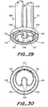
- Figure 29 illustrates a collapsible core assembly 189 which includes a collapsible cylinder 191 with a ring 192 attached to the lower portion of the cylinder.
- the cylinder is fabricated of a flexible plastic material such as polypropylene and is similar to core 181 in the embodiment of Figure 27.
- the ring has a generally U-shaped cross-section with an annular top wall 193 and a pair of depending flanges 194, 196. It is fabricated of a rigid material and can, for example, be formed of plastic by vacuum forming or injection molding.
- the cylinder is disposed within the ring and is attached to inner flange 194 by rivets 197 over about 60° of its circumference. The remainder of the cylinder is free to collapse and expand within the ring.
- a pair of pins 198 project outwardly in a radial direction from the cylinder and are received in openings 199 in the inner flange of the ring when the cylinder is expanded. The pins are spaced about 60° apart and are positioned opposite the rivets.
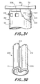
- core assembly 189 is mounted on the outlet side of dispensing valve 12 by means of a pair of retractable latches or hooks 201 on the cylindrical collar 73 of transition piece 68.
- the latches have a horizontally extending upper surface 202 and a downwardly and inwardly inclined side surface 203, and they are movable between the extended position shown in solid lines in Figure 31 and the retracted position shown in broken lines.
- the latches are urged toward the extended position by springs (not shown).
- Latches 201 are received in openings 206 in the upper portion of cylinder 191. Even though there are only two latches, the openings are spaced about the entire periphery of the cylinder so the operator does not have to worry about the orientation of the cylinder while mounting it on the dispenser.
- core assembly 189 is removed from the dispenser, and cylinder 191 is collapsed and inserted into a bundle of tubing 152.
- the cylinder is then expanded and mounted on the dispenser.
- the cylinder is moved in an upward direction onto collar 73, it engages the inclined side surfaces 203 of the latches and depresses them.
- the latches snap to their extended position and thereafter hold the cylinder on the dispenser.
- the lower portion of the tubing 23 is drawn over the ring, and successive sections of the tubing can then be withdrawn from the core and filled with the loose fill material as in the other embodiments.
- the core assembly is removed from the dispenser by manually depressing latches 201 to disengage them from the openings in the core cylinder whereupon the core will drop and can be moved away from the dispenser.
- the core assembly of Figure 29 can also be mounted on the dispenser by other means such as the fingers and hooks of Figure 15 and some of the other embodiments.
- the length of the core is not limited by the length of the fingers, and longer cores with more tubing can be employed.
- Figure 32 illustrates a collapsible core assembly 208 which has a collapsible cylinder 209 with a flexible ring 211 attached to the lower portion of the cylinder.
- the cylinder is fabricated of a flexible plastic material such as polypropylene and is similar to core 191 in the embodiment of Figure 29.
- the ring is fabricated of a flexible material and is secured all the way around the cylinder.
- ring 211 has a generally circular cross-section, and it can is fabricated of a tubular plastic material.
- the ring can be fabricated of any material which will flex with the cylinder, and it can be solid or hollow.
- Openings 212 are formed in the upper portion of the cylinder for mounting the core on the dispenser, as in the embodiment of Figure 29.
- core assembly 208 Operation and use of core assembly 208 is similar to that of core assembly 189 except that ring 211 flexes with cylinder 209 as it is collapsed and expanded.
- Core assembly 208 can also be mounted by other means such as the fingers and hooks of Figure 15 and some of the other embodiments. With those hooks, ring 211 can be spaced a short distance above the lower edge of the cylinder to provide clearance for the hooks.
- the invention has a number of important features and advantages. It enables packing cushions to be manufactured at the point of use quickly and economically without the spillage and mess normally associated with loose fill materials. It also eliminates the problems of messiness and spillage at the receiving end when the cartons are opened and the articles packed therein are removed. Being contained in the cushions, the loose fill material will not tend to cling to the articles packed in it or to the hands and arms of a person removing the articles from it.
- the cushions also prevent the packaged goods from contact with materials such as starch which tend to absorb water and become soggy during humid conditions.
- the cushions can be molded to the shape of the articles to be protected, and tend to provide better protection than a loose body of material. If desired, advertising and/or other messages can be printed on the bags.
Landscapes
- Engineering & Computer Science (AREA)
- Mechanical Engineering (AREA)
- Containers And Plastic Fillers For Packaging (AREA)
- Buffer Packaging (AREA)
Claims (11)
- Verfahren zum Füllen von Kissen unter Verwendung einer Vorrichtung zum Packen von schüttfähigem Material in Kissenmit einem Trichter (11) für die Lagerung des schüttfähigen Verpackungsmaterials, der ein Ende für die Abgabe des schüttfähigen Materials aufweist,mit Einrichtungen (12) zum Betätigen der Vorrichtung für die Abgabe von schüttfähigem Verpackungsmaterial aus dem Trichter (11),mit einem Längenstück eines flexiblen Schlauchs (23), das axial zusammengelegt und koaxial zum Trichterabgabeende so angeordnet ist, dass aufeinanderfolgende Abschnitte des Schlauchs (23) abgezogen, mit dem schüttfähigen Material gefüllt und zur Bildung von Kissen verschlossen werden können,mit Einrichtungen (33) zum Verschließen aufeinanderfolgender Abschnitte des Schlauchs (23) zur Bildung der Kissen aus den gefüllten Beuteln, wobei die Einrichtungen (33) zwei axial voneinander beabstandete Schließbänder (37) auf den Schlauch (23) aufbringen können, um gleichzeitig ein erstes Ende des ersten Schlauchabschnitts zu schließen und ein geschlossenes Ende für einen zweiten darauffolgenden Schlauchabschnitt bereitzustellen, undmit Einrichtungen (39) zum Abschneiden des Schlauchs (23) zwischen den zwei Schließbändern (37) zum Trennen aufeinanderfolgender Schlauchabschnitte,wobei das Verfahren die Schritte aufweist,die Vorrichtung unter Verwendung der Einrichtungen (12) so zu betätigen, dass schüttfähiges Material in einen ersten Abschnitt des Schlauchs (23) abgegeben wird,gleichzeitig den ersten und einen zweiten darauffolgenden Abschnitt des Schlauchs (23) durch Anlegen von zwei axial beabstandeten Schließbändern zwischen dem ersten und zweiten Schlauchabschnitt unter Verwendung der Einrichtungen (33) zu verschließen undden Schlauch (23) zwischen den beiden Schließbändern unter Verwendung der Einrichtungen (39) zu trennen, um dem zweiten Schlauchabschnitt ein geschlossenes Ende zu geben und ein von dem ersten gefüllten Schlauchabschnitt gebildetes Kissen bereitzustellen.
- Verfahren nach Anspruch 1, bei welchem die verschließenden Einrichtungen (33) der Vorrichtung mit Hilfe eines Bandes, von Wärme, von Metallklammern, von Drahtbindern oder Kunststoffbindern abdichtend verschließen.
- Verfahren nach Anspruch 2, bei welchem die Einrichtungen (33) der Vorrichtung ein Paar von Bandanlegern (117) aufweisen, die nebeneinander angeordnet und miteinander für eine gemeinsame Drehung um eine Achse verbunden sind, die insgesamt senkrecht zur Achse des Schlauchs (23) ist.
- Verfahren nach Anspruch 2 oder 3, bei welchem das Band der Vorrichtung auf Rollen (107) gespeichert ist, die auf Naben (108) mit Stößeln (113) angeordnet sind, die in Eingriff mit den Rollen (107) auf den Naben (108) vorgespannt sind.
- Verfahren nach Anspruch 2, 3 oder 4, bei welchem das Band der Vorrichtung auf Rollen (107) gespeichert ist, die drehbar an Naben (108) mit Halteplatten (109) angeordnet sind, die in Schlitzen (110) in den Naben (108) zum Halten der Rollen (107) an den Naben (108) sitzen.
- Kombination eines schüttfähigen Verpackungsmaterials für Kissen und einer Vorrichtung zum Packen des schüttfähigen Materials in Kissen, wobei die Vorrichtungeinen Trichter (11), der schüttfähiges Material enthält und ein Ende für die Abgabe des schüttfähigen Materials hat,Einrichtungen (12) zum Betätigen der Vorrichtung zur Abgabe des schüttfähigen Verpackungsmaterials aus dem Trichter (11),ein Längenstück des flexiblen Schlauchs (23), das axial zusammengelegt und koaxial an dem Trichterabgabeende so angeordnet ist, dass aufeinanderfolgende Abschnitte des Schlauchs (23) abgezogen, mit schüttfähigem Material gefüllt und zur Bildung von Kissen verschlossen werden können,Einrichtungen (33) zum Verschließen aufeinanderfolgender Abschnitte des Schlauchs (33) zur Bildung der Kissen aus den gefüllten Beuteln, wobei die Einrichtungen (33) zum Anliegen von zwei axial im Abstand angeordneten Schließbändem (37) an den Schlauch (23) angepasst sind, um gleichzeitig ein erstes Ende eines Schlauchabschnitts zu schließen und um ein geschlossenes Ende für einen zweiten darauffolgenden Schlauchabschnitt bereitzustellen, undEinrichtungen (39) zum Abschneiden des Schlauchs (23) zwischen den zwei Schließbändern (37) aufweist, um aufeinanderfolgende Schlauchabschnitte zu trennen.
- Vorrichtung nach Anspruch 6, bei welcher das schüttfähige Verpackungsmaterial für die Kissen Polystyrolkugeln, Stärkepfropfkopolymermaterialien, Stärkebiopolymermaterialien, Holzschnitzel, Pflanzenfasern, Zweige, Samenkörner oder Popkorn aufweist.
- Vorrichtung nach Anspruch 6 oder Anspruch 7, bei welcher die verschließenden Einrichtungen (33) mit Hilfe eines Bandes, von Wärme, von Metallklammern, von Drahtbindern oder Kunststoffbindern abdichtend verschließen.
- Vorrichtung nach Anspruch 8, bei welcher die Einrichtungen (33) ein Paar von Bandanlegern (117) aufweisen, die nebeneinander angeordnet und miteinander für eine gemeinsame Drehung um eine Achse verbunden sind, die insgesamt senkrecht zur Achse des Schlauchs (23) ist.
- Vorrichtung nach Anspruch 8 oder 9, bei welcher das Band auf Rollen (107) gespeichert ist, die an Naben (108) mit Stößeln (113) angeordnet sind, die in Eingriff mit den Rollen (107) auf den Naben (108) vorgespannt sind.
- Vorrichtung nach Anspruch 8, 9 oder 10, bei welcher das Band auf Rollen (107) gespeichert ist, die drehbar an Naben (108) mit Halteplatten (109) angeordnet sind, die in Schlitzen (110) in den Naben (108) zum Halten der Rollen (107) an den Naben (108) sitzen.
Applications Claiming Priority (8)
| Application Number | Priority Date | Filing Date | Title |
|---|---|---|---|
| US08/673,296 US5826404A (en) | 1993-08-02 | 1996-06-28 | System and method for use of loose fill packing materials |
| US673296 | 1996-06-28 | ||
| US08/766,156 US5778642A (en) | 1996-06-28 | 1996-12-12 | System and method for use of loose fill packing materials |
| US816114 | 1997-03-11 | ||
| US08/816,114 US5782067A (en) | 1996-06-28 | 1997-03-11 | Bag sealer and cutter for use in packaging loose fill packaging materials |
| US08/843,914 US5782061A (en) | 1996-06-28 | 1997-04-17 | System and method for making cushions of loose fill packing material |
| US843914 | 1997-04-17 | ||
| US766156 | 2001-01-19 |
Publications (3)
| Publication Number | Publication Date |
|---|---|
| EP0816228A2 EP0816228A2 (de) | 1998-01-07 |
| EP0816228A3 EP0816228A3 (de) | 1998-05-20 |
| EP0816228B1 true EP0816228B1 (de) | 2002-10-02 |
Family
ID=27505355
Family Applications (1)
| Application Number | Title | Priority Date | Filing Date |
|---|---|---|---|
| EP19970304660 Expired - Lifetime EP0816228B1 (de) | 1996-06-28 | 1997-06-27 | Vorrichtung und Verfahren zum Herstellen von mit schüttfähigem Material gefüllten Verpackungspolsterkissen |
Country Status (2)
| Country | Link |
|---|---|
| EP (1) | EP0816228B1 (de) |
| DE (1) | DE69715973T2 (de) |
Cited By (1)
| Publication number | Priority date | Publication date | Assignee | Title |
|---|---|---|---|---|
| US8906478B2 (en) | 2005-05-06 | 2014-12-09 | Pregis Innovative Packaging, Inc. | Films for inflatable cushions |
Families Citing this family (5)
| Publication number | Priority date | Publication date | Assignee | Title |
|---|---|---|---|---|
| GB0114312D0 (en) † | 2001-06-12 | 2001-08-01 | Sangenic International Ltd | Spool for a waste storage device |
| US8627637B2 (en) | 1999-09-22 | 2014-01-14 | Pregis Innovative Packaging, Inc. | Method and machine for the manufacture of air pillows |
| ES2226449T3 (es) | 1999-09-22 | 2005-03-16 | Pactiv Corporation | Metodo y maquina para la fabricacion de cojines de aire. |
| US6932134B2 (en) | 2003-02-07 | 2005-08-23 | Pactiv Corporation | Devices and methods for manufacturing packaging materials |
| CN111776447A (zh) * | 2020-07-21 | 2020-10-16 | 南京高宁锻造法兰厂 | 一种法兰运输刀口防磕保护装置 |
Family Cites Families (6)
| Publication number | Priority date | Publication date | Assignee | Title |
|---|---|---|---|---|
| FR1196228A (fr) * | 1959-03-16 | 1959-11-23 | Sacherie D Artois | Dispositif pour l'ensachage en filet tubulaire |
| US3281089A (en) * | 1965-03-22 | 1966-10-25 | Alwin Mfg Company | Core brake for a web dispenser |
| GB1564397A (en) * | 1976-10-12 | 1980-04-10 | Banks C H | Apparatus for sealing tubular packaging material |
| IT1241222B (it) * | 1990-05-09 | 1993-12-29 | Irico S P A | Macchina automatica per la nastratura ed il taglio di fasci di fibre |
| NL9201621A (nl) * | 1992-09-18 | 1994-04-18 | Novem Trading Int Bv | Omsnoeringsinrichting. |
| DE9314731U1 (de) * | 1993-09-29 | 1993-12-16 | DDS-Maschinenbau-GmbH, 88682 Salem | Vorrichtung zur Herstellung von Ausfüllmaterial, insbesondere für Verpackungszwecke |
-
1997
- 1997-06-27 EP EP19970304660 patent/EP0816228B1/de not_active Expired - Lifetime
- 1997-06-27 DE DE1997615973 patent/DE69715973T2/de not_active Expired - Fee Related
Cited By (1)
| Publication number | Priority date | Publication date | Assignee | Title |
|---|---|---|---|---|
| US8906478B2 (en) | 2005-05-06 | 2014-12-09 | Pregis Innovative Packaging, Inc. | Films for inflatable cushions |
Also Published As
| Publication number | Publication date |
|---|---|
| EP0816228A3 (de) | 1998-05-20 |
| DE69715973D1 (de) | 2002-11-07 |
| EP0816228A2 (de) | 1998-01-07 |
| DE69715973T2 (de) | 2003-09-11 |
Similar Documents
| Publication | Publication Date | Title |
|---|---|---|
| US5782067A (en) | Bag sealer and cutter for use in packaging loose fill packaging materials | |
| US5899049A (en) | System and method for making cushions of loose fill packing material | |
| US5826404A (en) | System and method for use of loose fill packing materials | |
| US5078269A (en) | Wire shipping and dispensing container | |
| CA2075853C (en) | Dispensing apparatus for plastic bags | |
| KR101322189B1 (ko) | 무동력 완충재 장치 | |
| CA2046887C (en) | Packaging method and apparatus | |
| US4300326A (en) | Stretch wrapping apparatus with mechanical closure | |
| CA1169349A (en) | Stretch wrapping apparatus and process | |
| US20120055119A1 (en) | Packaging material | |
| US5181614A (en) | Coil dunnage and package using same | |
| US5782061A (en) | System and method for making cushions of loose fill packing material | |
| US5778642A (en) | System and method for use of loose fill packing materials | |
| US6534136B2 (en) | Packaging material | |
| FI67471C (fi) | Foerfarande foer att placera en dimensioneringsskiva i ett slangformigt hoelje och anordning foer tillaempning av detta forfarande | |
| US20130118131A1 (en) | Flexible, inflatable packaging materials and methods of making and using same | |
| EP0816228A2 (de) | Vorrichtung und Verfahren zum Herstellen von mit schüttfähigem Material gefüllten Verpackungspolsterkissen und mit diesem hergestellte Kissen | |
| US9611059B2 (en) | Flexible packaging materials and methods of making and using same | |
| GB1564397A (en) | Apparatus for sealing tubular packaging material | |
| US20240308168A1 (en) | Dunnage production system | |
| US3455088A (en) | Container delivery apparatus | |
| EP0501260A1 (de) | Papiertücher-Verpackung | |
| US6009689A (en) | Packaging a strip of material in layers | |
| US20050221031A1 (en) | Flexible packaging materials and methods of making and using same | |
| AU2006201832B8 (en) | Fragrance detectable wrapped soap bar |
Legal Events
| Date | Code | Title | Description |
|---|---|---|---|
| PUAI | Public reference made under article 153(3) epc to a published international application that has entered the european phase |
Free format text: ORIGINAL CODE: 0009012 |
|
| AK | Designated contracting states |
Kind code of ref document: A2 Designated state(s): DE ES FR GB IT NL |
|
| PUAL | Search report despatched |
Free format text: ORIGINAL CODE: 0009013 |
|
| AK | Designated contracting states |
Kind code of ref document: A3 Designated state(s): AT BE CH DE DK ES FI FR GB GR IE IT LI LU MC NL PT SE |
|
| 17P | Request for examination filed |
Effective date: 19981008 |
|
| AKX | Designation fees paid |
Free format text: AT BE CH DE DK ES LI |
|
| RBV | Designated contracting states (corrected) |
Designated state(s): AT BE CH DE DK ES LI |
|
| 17Q | First examination report despatched |
Effective date: 19990716 |
|
| RBV | Designated contracting states (corrected) |
Designated state(s): DE ES FR GB IT NL |
|
| RBV | Designated contracting states (corrected) |
Designated state(s): DE ES FR GB IT |
|
| RTI1 | Title (correction) |
Free format text: SYSTEM AND METHOD FOR MAKING CUSHIONS OF LOOSE FILL PACKING MATERIAL |
|
| GRAG | Despatch of communication of intention to grant |
Free format text: ORIGINAL CODE: EPIDOS AGRA |
|
| RTI1 | Title (correction) |
Free format text: SYSTEM AND METHOD FOR MAKING CUSHIONS OF LOOSE FILL PACKING MATERIAL |
|
| RBV | Designated contracting states (corrected) |
Designated state(s): DE ES FR GB IT NL |
|
| GRAG | Despatch of communication of intention to grant |
Free format text: ORIGINAL CODE: EPIDOS AGRA |
|
| GRAG | Despatch of communication of intention to grant |
Free format text: ORIGINAL CODE: EPIDOS AGRA |
|
| GRAH | Despatch of communication of intention to grant a patent |
Free format text: ORIGINAL CODE: EPIDOS IGRA |
|
| GRAH | Despatch of communication of intention to grant a patent |
Free format text: ORIGINAL CODE: EPIDOS IGRA |
|
| GRAA | (expected) grant |
Free format text: ORIGINAL CODE: 0009210 |
|
| AK | Designated contracting states |
Kind code of ref document: B1 Designated state(s): DE ES FR GB IT NL |
|
| PG25 | Lapsed in a contracting state [announced via postgrant information from national office to epo] |
Ref country code: NL Free format text: LAPSE BECAUSE OF FAILURE TO SUBMIT A TRANSLATION OF THE DESCRIPTION OR TO PAY THE FEE WITHIN THE PRESCRIBED TIME-LIMIT Effective date: 20021002 Ref country code: IT Free format text: LAPSE BECAUSE OF FAILURE TO SUBMIT A TRANSLATION OF THE DESCRIPTION OR TO PAY THE FEE WITHIN THE PRESCRIBED TIME-LIMIT;WARNING: LAPSES OF ITALIAN PATENTS WITH EFFECTIVE DATE BEFORE 2007 MAY HAVE OCCURRED AT ANY TIME BEFORE 2007. THE CORRECT EFFECTIVE DATE MAY BE DIFFERENT FROM THE ONE RECORDED. Effective date: 20021002 |
|
| REG | Reference to a national code |
Ref country code: GB Ref legal event code: FG4D |
|
| REF | Corresponds to: |
Ref document number: 69715973 Country of ref document: DE Date of ref document: 20021107 |
|
| NLV1 | Nl: lapsed or annulled due to failure to fulfill the requirements of art. 29p and 29m of the patents act | ||
| ET | Fr: translation filed | ||
| PG25 | Lapsed in a contracting state [announced via postgrant information from national office to epo] |
Ref country code: ES Free format text: LAPSE BECAUSE OF FAILURE TO SUBMIT A TRANSLATION OF THE DESCRIPTION OR TO PAY THE FEE WITHIN THE PRESCRIBED TIME-LIMIT Effective date: 20030429 |
|
| PG25 | Lapsed in a contracting state [announced via postgrant information from national office to epo] |
Ref country code: GB Free format text: LAPSE BECAUSE OF NON-PAYMENT OF DUE FEES Effective date: 20030627 |
|
| PLBE | No opposition filed within time limit |
Free format text: ORIGINAL CODE: 0009261 |
|
| STAA | Information on the status of an ep patent application or granted ep patent |
Free format text: STATUS: NO OPPOSITION FILED WITHIN TIME LIMIT |
|
| 26N | No opposition filed |
Effective date: 20030703 |
|
| PG25 | Lapsed in a contracting state [announced via postgrant information from national office to epo] |
Ref country code: DE Free format text: LAPSE BECAUSE OF NON-PAYMENT OF DUE FEES Effective date: 20040101 |
|
| GBPC | Gb: european patent ceased through non-payment of renewal fee |
Effective date: 20030627 |
|
| PG25 | Lapsed in a contracting state [announced via postgrant information from national office to epo] |
Ref country code: FR Free format text: LAPSE BECAUSE OF NON-PAYMENT OF DUE FEES Effective date: 20040227 |
|
| REG | Reference to a national code |
Ref country code: FR Ref legal event code: ST |