EP0816257A1 - Vorrichtung zum Lagern von Flüssigkeiten, deren Herstellungsverfahren sowie mit einer solchen Vorrichtung versehene Feuerhydranten - Google Patents
Vorrichtung zum Lagern von Flüssigkeiten, deren Herstellungsverfahren sowie mit einer solchen Vorrichtung versehene Feuerhydranten Download PDFInfo
- Publication number
- EP0816257A1 EP0816257A1 EP97401398A EP97401398A EP0816257A1 EP 0816257 A1 EP0816257 A1 EP 0816257A1 EP 97401398 A EP97401398 A EP 97401398A EP 97401398 A EP97401398 A EP 97401398A EP 0816257 A1 EP0816257 A1 EP 0816257A1
- Authority
- EP
- European Patent Office
- Prior art keywords
- storage device
- pump
- well
- liquid
- plate
- Prior art date
- Legal status (The legal status is an assumption and is not a legal conclusion. Google has not performed a legal analysis and makes no representation as to the accuracy of the status listed.)
- Withdrawn
Links
Images


Classifications
-
- B—PERFORMING OPERATIONS; TRANSPORTING
- B67—OPENING, CLOSING OR CLEANING BOTTLES, JARS OR SIMILAR CONTAINERS; LIQUID HANDLING
- B67D—DISPENSING, DELIVERING OR TRANSFERRING LIQUIDS, NOT OTHERWISE PROVIDED FOR
- B67D7/00—Apparatus or devices for transferring liquids from bulk storage containers or reservoirs into vehicles or into portable containers, e.g. for retail sale purposes
- B67D7/06—Details or accessories
- B67D7/58—Arrangements of pumps
- B67D7/68—Arrangements of pumps submerged in storage tank or reservoir
-
- A—HUMAN NECESSITIES
- A62—LIFE-SAVING; FIRE-FIGHTING
- A62C—FIRE-FIGHTING
- A62C35/00—Permanently-installed equipment
- A62C35/02—Permanently-installed equipment with containers for delivering the extinguishing substance
- A62C35/026—Permanently-installed equipment with containers for delivering the extinguishing substance the extinguishing material being put under pressure by means other than pressure gas, e.g. pumps
-
- B—PERFORMING OPERATIONS; TRANSPORTING
- B67—OPENING, CLOSING OR CLEANING BOTTLES, JARS OR SIMILAR CONTAINERS; LIQUID HANDLING
- B67D—DISPENSING, DELIVERING OR TRANSFERRING LIQUIDS, NOT OTHERWISE PROVIDED FOR
- B67D7/00—Apparatus or devices for transferring liquids from bulk storage containers or reservoirs into vehicles or into portable containers, e.g. for retail sale purposes
- B67D7/06—Details or accessories
- B67D7/78—Arrangements of storage tanks, reservoirs or pipe-lines
Definitions
- the present invention relates to devices storage of bulk products, especially liquids or heavy products, their production process and fire hydrants including such device.
- Reservoirs of known types have many disadvantages.
- the underground tanks are complex to implement and cost Student.
- Surface-built tanks occupy a volume and a large surface compared to their capacity.
- the flexible tanks are unsightly and fragile.
- a cylindrical well lined with a coating waterproof, in particular a flexible bag and / or pocket the internal volume in the well increases during filling of the storage device and decreases when its emptying.
- the walls of the flexible pocket are stretched and / or suspended when it is not completely filled.
- the walls of the pocket are by example made of plastic advantageously reinforced by a flexible or elastic framework in particular made of fibers or comprising metallic cables.
- the flexible pocket is provided with means extraction of its contents, for example a pump for liquids, an Archimedes screw or a noria of cups for heavy products.
- the main object of the invention is a liquid product storage device comprising a well dug in the ground and a watertight flexible envelope that is, at least when the storage device is filled with said liquid, shaped or substantially conformed to the walls of the well, so as to form a reception volume of the liquid product to be stored, characterized in that it includes an extraction pump liquid from the storage device arranged in the waterproof flexible envelope, preferably at the bottom of the well, so that the pump is submerged when the envelope is filled with a liquid, said pump being connected to a liquid extraction pipe from the liquid storage device.
- the subject of the invention is also a storage device, characterized in that the pump is placed at the bottom of the well.
- the invention also relates to a device storage, characterized in that the flexible envelope is a closed envelope.
- the subject of the invention is also a storage device characterized in that the well is cylindrical or substantially cylindrical.
- the invention also relates to a device storage, characterized in that the depth of the well is greater than or equal to its diameter or width.
- the subject of the invention is also a storage device, characterized in that it comprises a first horizontal rigid wall or substantially horizontal arranged above the flexible envelope and forming the floor of a technical room and a second horizontal or substantially horizontal wall forming a access hatch and / or the ceiling of the technical room.
- the invention also relates to a device storage, characterized in that the second wall is found substantially at ground level.
- the subject of the invention is also a storage device, characterized in that the pump submerged is a motor pump placed at the bottom of the well.
- the invention also relates to a device storage characterized in that it comprises a motor located in the technical room and a pump located in the bottom of the well so that the pump is submerged when the envelope is filled with liquid and it has a pump drive shaft by engine.
- the subject of the invention is also a storage device characterized in that it comprises a flow and / or pressure test device delivered by the pump or motor pump with pipes and liquid stopping means, in particular valves, ensuring during a test the circulation in closed circuit of the liquid contained in the envelope.
- the invention also relates to a device, characterized in that the flexible envelope is sealed in its upper part on a plate suspended by these cables attached to anchor points.
- the invention also relates to a terminal fire-fighting systems with a supply of water connected to a tubular pipe terminated by a fire hose, characterized in that the supply in water includes a storage device.
- the invention also relates to a terminal for fire fighting, characterized in that it has a base arranged above the well.
- the invention also relates to a terminal fire fighting, characterized in that it has a valve to purge the pipe tubular.
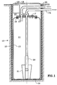
- a storage device 10 comprising a well 11, preferably cylindrical defined by nozzles 12 for example of concrete or plastic forming the structure of the storage device , lined with a flexible membrane 13 ensuring the tightness of the storage device.
- the membrane is for example made of woven polyester coated with PVC on its two faces having 0.92 mm thick and a mass of 1.2 kg / m 2 . It can be covered on its external face directed towards the nozzles with protection, for example in synthetic fabric in order to protect it against possible friction on the nozzles 12.
- a perforated plate 14 for example metallic or made of synthetic material placed on the bottom of the well supports the bottom of the pocket formed by the membrane 13.
- the membrane 13 may be free in the well or be regularly anchored to the nozzles 12. Depending on the configuration of the terrain it may prove advantageous to have vertically on the height of the well 11 a tubular pipe (not shown) pierced with rainwater drainage holes or infiltrated into the well.
- the upper edge of the membrane 13 is secured to a rigid plate 15, for example by crimping between the plate 15 and a against plate or washer 16.
- Plate 15 fixed to well 11 by pipes or by means other than represents ensures the hermetic sealing of the pocket formed by the flexible membrane 13, supports means supply and extraction of the content of the storage, for example of the sealed grommet type and / or cable gland connected to one or more pipes tubular and plays the role, or for diameters important features, a technical hatch allowing to access the inside of the pocket.
- the pocket is hermetically sealed and communicates with the outside only by pipes passing from sealed by the flexible membrane 13.
- the pocket is sealed in the part superior, for example by heat sealing, or otherwise is left open for example for collect runoff water.
- the plate 15 is suspended by cables, chains 31 or, advantageously by elastic return elements working in traction, in elastomer or, preferably, springs with sausage, attached to the anchor points 32 of the well 11.
- the plate 15 of Figure 1 can be put in work with the storage devices of figures 2 to 4 as well as the plate 15 of figures 2 to 4 can be implementation with the storage devices of the figure 1.
- the storage device according to the invention can be put under pressure of up to or exceed several bars (several hundred thousand of Pascals), or on the contrary be put in depression, the decreasing internal volume of the membrane (the pocket is deflating) during emptying. So it may turn out necessary to provide plate 15 with a degassing vent 17, a calibrated safety valve or valve on the maximum working pressure of the storage device.
- the plate 15 is located at ground level, or, advantageously, at a depth making it possible to provide, between the plate 15 and a plate 18, for example of cast iron situated substantially at ground level, a technical room 19.
- the plate 18 can be provided thermal insulation to guarantee that a liquid contained in the storage device is kept out of frost.
- the storage device according to the invention comprises means for extracting its content.
- the extraction means comprise for example an Archimedes screw opening at the surface or above the surface of the ground.
- the extraction means of the liquid storage device comprise a pump.
- the storage device comprises a submerged motor pump 20 disposed near the bottom of the pocket.
- the water intake of the pump 20 is surrounded by a strainer 21 preventing the obstruction of the pump by possible impurities present in the liquid contained in the bag.
- the technical room 19 advantageously comprises an electrical cabinet 22 comprising the electrical supply to the pump, means for controlling the pump and / or a device for testing its correct operation.
- the test device operates in a closed hydraulic circuit.
- the bag is supplied with water by a water inlet pipe 23, the pump 20 supplies pressurized water with an outlet pipe 24.
- the water inlet pipe 23 is fitted with a non-return valve and the pipes 23 and 24 are connected by a solenoid valve and by a pressure and / or flow measurement device, a second solenoid valve closes the outlet of the pipe 24.
- a PLC or operator triggers the operation of pump 20, measures the resulting pressure and / or flow rate and issues an alarm signal if the measured flow rate or pressure does not correspond to a minimum value.
- the storage device may include a device for measuring the level of liquid in the pocket disposed on the wall 13 or on a dip tube for extracting water from the storage device.
- a safety device stops the pump when the storage device is empty.
- the storage device of Figure 1 is particularly well suited for water tanks intended for fire fighting.
- the submerged pump 20 provides high pressures, for example between 6 bars (6 x 10 5 Pa) and 12 bars (12 x 10 5 Pa) necessary for firefighters to effectively fight a fire.
- Such a pump is always primed and therefore particularly reliable. It is possible, for example, to use pumps sold under the name Guinard KSB type UPA 150 S -12/7 + FK4, with a power of 3.7 kW, having a diameter of 0.1524 m and providing a flow rate of 10 m 3 at 6.5 bars (6.5 x 10 5 Pa).
- the pump 20 is placed at the bottom of the pocket over a height of 1.6m, the strainer 21 extending over 0.9m, the well having a diameter of lm and a depth of 5m, the first of which meter from ground level is reserved for the room technique 19.
- the well has a diameter included between 0, lm and 12m, preferably between 0.5m and 5m, advantageously between 0.7m and 3m, so preferential between 0.9m and 2m.
- the depth of well is between lm and 50m, preferably between 2m and 25m, advantageously between 3m and 12m, preferably between 5m and 10m.
- the relationship between the depth and the diameter of the well is greater than or equal to 1, of preferably greater than or equal to 2, so preferential greater than or equal to 5, for example equal to 4, 5, 8 or 10.
- a cylindrical well is more easy to make, wells can be used having other shapes, for example square section or rectangular or wells extended by galleries increasing the storage volume.
- Well 11 has preferably a vertical axis. However, this axis can be slightly tilted to make the most of the terrain configuration.
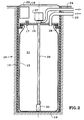
- the variant illustrated on the Figure 2 comprises a submerged pump 25 driven in rotation by a very long shaft 26, advantageously flexible, extending up to a motor 27, preferably electrical arranged in the room technique 19.
- the shaft 26 is coaxial with a water outlet tube pumped by pump 25.
- the storage device according to the invention of Figure 3 includes a 128 motor pump placed in the room technique 19 and including a suction pump 29 driven by an advantageously electric motor 30.
- the storage device according to the invention illustrated on the Figure 4 does not include a pump.
- the tip of her dip tube 31 is intended to be connected to a pump external or to a siphon for water supply (or other liquids) from areas at an altitude lower than that of the storage device. for example a storage device according to the invention of the figure 4 placed on the side of a hill can replace a water tower for the supply of drinking water to a agglomeration located below.
- the pocket inflates during filling and deflates when the storage device is emptied.
- the pocket has reinforcements or anchors in the well nozzles so as to keep a substantially constant volume, when filling the air is expelled from the pocket and passes through vent 17 and when the storage device is emptied air enters the pocket through said vent.
- FIG. 5 we can see the example preferred to achieve a fight kiosk fire 33 according to the present invention provided with a storage device for example of 2300 liters of water.
- Well 11 consists of concrete nozzles 12 of one meter in diameter and 3.5 meters deep.
- the well is closed by a manhole cast iron (not shown).
- the flexible membrane 13 is by example made of fabric impregnated with polychloride vinyl (PVC in Anglo-Saxon terminology) on both main faces.
- PVC polychloride vinyl
- the flexible membrane 13 is sealed hermetically on a polypropylene plate 15 serving manhole and technical support.
- Plate 15 is provided with means 34 for attaching ends lower suspension cables 31 whose upper ends are attached to points anchor 32 fixed for example to the nozzles 12 of the well 11.
- a submerged motor pump for example made of stainless steel delivering, on command, water at a pressure of 85 10 4 Pa for a flow rate of 200 liters / minute.
- the accessible elements of the fire hydrant according to the present invention are fixed above well 11 on a precast concrete base 35, secured to the nozzles 12 by clips 39.
- a chassis 36 advantageously completed by an upper cover 37 for protection against severe weather.
- a metal or material cover 38 plastic closes the manhole.
- the fire fighting terminal is of type RIA (Armed Fire Valve) and includes a rotary reel 42 on which a pipe is wound semi-rigid tubular 43 of which a first end is connected to the tubular pipe 61 supplied by the pump 20 and the opposite end of which is provided with a lance 44 fitted with a valve 45.
- RIA Armed Fire Valve
- the lance 44 is a medium foam lance expansion, a container of foam concentrate 46 being connected to a metering injector 47 disposed on the pipeline water supply.
- the aspiration of the emulsifier by venturi effect and its mixture with water create abundant foam with a lance 44.
- Terminal 33 is advantageously equipped with a 48 gauge for measuring the water level available in the envelope 13.
- a detector 49 detects when the minimum water level is reached in envelope 13 of so as to activate the pump stop system 50 so as to avoid its deterioration by lack of water.
- the device comprises test means with closed circuit water flow or, advantageously, as illustrated without water flow.
- he comprises for example a motorized valve 51 which, in closed condition, confines the water and makes it possible to check the correct operation of pump 20 and avoid its clogging.
- an electronic timer advantageously with backup of the time counted down in case of electrical cut-off, triggers every two weeks the valve 51 and starts pump 20 for one minute.
- security allows in case of need to force valve 51 to open on simple action of the rotary start button 40.
- a tubular pipe for supplying water to the casing 13 is provided with a non-return valve 53.
- Possible protection against frost device 33 is adapted to the climate of the place of installation.
- the device can be fitted with pressure detection in the pipe tubular 43, armed or not. Opening valve 45 causes pump 20. to start. valve closed, pressure switch (not shown) stop pump 20.
- the fire hydrant purges itself automatically after a use for frost protection.
- the rotary button 40 After use it just clean the tubular pipe 43 of the product emulsifier, put the rotary button 40 on the "off" position, to fully unwind the pipe tubular 43 of the reel 42, to open the valve of the lance, let the water run out of the pipe tubular 43 for a few minutes, rewind the line 43 on the unwinder 42, to close the valve 45 of lance before replacing it on its support.
- the system will be ready to operate again when the booster water will have been carried out.
- the tank may be provided with frost-free heating means.
- the switch In the event of a fire, the switch is operated 40 in the "on" position. Pump 20 starts up and keeps the semi-rigid tubular pipe 43 under pressure on the reel 42.
- the tubular pipe 43 is unwound by pulling on lance 44 until reaching the objective and we operates valve 45 backwards by directing the lance towards the foyer.
- closing valve 45 of lance 44 stops the pump. Terminal 33 is put on standby.
- the storage device applies to the construction of fire-fighting tanks, of potable water tanks, in particular of the type water tower, food storage liquids (wine, oil, etc.) or heavy (grain, fruit dry, etc ...), waste water storage or runoff awaiting treatment before discharge in a river, for thermal storage (cold water or hot), storage of hydrocarbons, sludge, betonite, cement, sand, gravel, mortar, concrete or small mechanical parts (bolts, rods, nails, etc ).
Landscapes
- Engineering & Computer Science (AREA)
- Mechanical Engineering (AREA)
- Health & Medical Sciences (AREA)
- Public Health (AREA)
- Business, Economics & Management (AREA)
- Emergency Management (AREA)
- Filling Or Discharging Of Gas Storage Vessels (AREA)
- Revetment (AREA)
Applications Claiming Priority (2)
| Application Number | Priority Date | Filing Date | Title |
|---|---|---|---|
| FR9607917 | 1996-06-26 | ||
| FR9607917A FR2750409B1 (fr) | 1996-06-26 | 1996-06-26 | Dispositif de stockage |
Publications (1)
| Publication Number | Publication Date |
|---|---|
| EP0816257A1 true EP0816257A1 (de) | 1998-01-07 |
Family
ID=9493417
Family Applications (1)
| Application Number | Title | Priority Date | Filing Date |
|---|---|---|---|
| EP97401398A Withdrawn EP0816257A1 (de) | 1996-06-26 | 1997-06-18 | Vorrichtung zum Lagern von Flüssigkeiten, deren Herstellungsverfahren sowie mit einer solchen Vorrichtung versehene Feuerhydranten |
Country Status (2)
| Country | Link |
|---|---|
| EP (1) | EP0816257A1 (de) |
| FR (1) | FR2750409B1 (de) |
Cited By (2)
| Publication number | Priority date | Publication date | Assignee | Title |
|---|---|---|---|---|
| DE202023100181U1 (de) | 2023-01-16 | 2023-02-06 | Dennis Horntasch | System zur Brandbekämpfung und Brandbekämpfungseinrichtung |
| DE102023100832A1 (de) | 2023-01-16 | 2024-07-18 | Dennis Horntasch | System zur Brandbekämpfung und Brandbekämpfungseinrichtung |
Citations (4)
| Publication number | Priority date | Publication date | Assignee | Title |
|---|---|---|---|---|
| CH358035A (de) * | 1957-07-26 | 1961-10-31 | Badertscher Hans | Lagertank für Flüssigkeiten |
| DE1811342A1 (de) * | 1968-11-28 | 1970-06-25 | Wilhelm Stappen Gmbh | Behaelter fuer Fluessigkeitslagerung,insbesondere fuer Heizoel |
| EP0005133A2 (de) * | 1978-04-26 | 1979-10-31 | Svenska Vägaktiebolaget | Explosionsfeste Anlage für die Aufbewahrung von Flüssiggasen |
| DE4006253A1 (de) * | 1990-02-28 | 1991-08-29 | Schmitz Gruenbau Gmbh | Behaelter zum speichern von regenwasser |
-
1996
- 1996-06-26 FR FR9607917A patent/FR2750409B1/fr not_active Expired - Fee Related
-
1997
- 1997-06-18 EP EP97401398A patent/EP0816257A1/de not_active Withdrawn
Patent Citations (4)
| Publication number | Priority date | Publication date | Assignee | Title |
|---|---|---|---|---|
| CH358035A (de) * | 1957-07-26 | 1961-10-31 | Badertscher Hans | Lagertank für Flüssigkeiten |
| DE1811342A1 (de) * | 1968-11-28 | 1970-06-25 | Wilhelm Stappen Gmbh | Behaelter fuer Fluessigkeitslagerung,insbesondere fuer Heizoel |
| EP0005133A2 (de) * | 1978-04-26 | 1979-10-31 | Svenska Vägaktiebolaget | Explosionsfeste Anlage für die Aufbewahrung von Flüssiggasen |
| DE4006253A1 (de) * | 1990-02-28 | 1991-08-29 | Schmitz Gruenbau Gmbh | Behaelter zum speichern von regenwasser |
Cited By (3)
| Publication number | Priority date | Publication date | Assignee | Title |
|---|---|---|---|---|
| DE202023100181U1 (de) | 2023-01-16 | 2023-02-06 | Dennis Horntasch | System zur Brandbekämpfung und Brandbekämpfungseinrichtung |
| DE102023100832A1 (de) | 2023-01-16 | 2024-07-18 | Dennis Horntasch | System zur Brandbekämpfung und Brandbekämpfungseinrichtung |
| DE102023100832B4 (de) | 2023-01-16 | 2025-01-30 | Dennis Horntasch | Brandbekämpfungseinrichtung und System zur Brandbekämpfung umfassend eine Vielzahl an Brandbekämpfungseinrichtungen |
Also Published As
| Publication number | Publication date |
|---|---|
| FR2750409B1 (fr) | 1998-08-14 |
| FR2750409A1 (fr) | 1998-01-02 |
Similar Documents
| Publication | Publication Date | Title |
|---|---|---|
| EP0013854B1 (de) | Sicherheitsverfahren und Vorrichtung für die unterirdische Lagerung von einem Fluidum unter Druck | |
| WO1994021957A1 (fr) | Systeme de regulation d'air pour reservoir hydropneumatique | |
| EP0116005A1 (de) | Vorrichtung für Frostschutz von Wasserzählern und Wasserhähnen | |
| FR2680393A1 (fr) | Procede et dispositif de commande d'une installation de pompage. | |
| JP2007063759A (ja) | 緊急用貯水装置及びそれを利用した消火装置 | |
| US5803111A (en) | Device for purging water supply line | |
| EP2616597B1 (de) | Vorrichtung zur reinigung von wasser aus einer sanitäranlage | |
| US7234484B2 (en) | Pressure tank apparatus and method | |
| EP2117995B1 (de) | Unterirdische lagerungseinrichtung für speiseöl | |
| FR2691637A1 (fr) | Dispositif de lutte contre les incendies. | |
| FR2750409A1 (fr) | Dispositif de stockage | |
| KR101439362B1 (ko) | 일체형 수중가압펌프장치 | |
| FR2728292A1 (fr) | Poste de refoulement prefabrique pour eaux usees, eaux pluviales ou eaux industrielles | |
| FR2972216A1 (fr) | Dispositif de pompage des hydrocarbures en milieu marin profond apres un sinistre | |
| EP4379184B1 (de) | Kopfabdeckungsvorrichtung und bohrlochpumpstation | |
| CA2362710C (fr) | Pompe a lixiviat et de depollution, pneumatique, a vanne a manchon | |
| FR2859637A1 (fr) | Dispositif permettant de liberer un liquide sous pression sur des lieux tels que des maisons d'habitation, pour les preserver des risques d'incendie. | |
| FR3022534B1 (fr) | Groupe de securite pour le remplissage et la vidange d'une cuve de stockage de produit chimique tel que de l'engrais liquide azote, et cuve a double paroi equipee | |
| BE563547A (de) | ||
| US20090078323A1 (en) | Air discharge device | |
| FR3101152A1 (fr) | Dispositif de detection de presence de liquide, cuvette de retention pour reservoir de liquide dangereux le comprenant, et systeme de detection de presence de liquide | |
| CA2325154A1 (en) | A water supply system and pump apparatus therefor | |
| JP2003119835A (ja) | 雨水利用装置 | |
| FR2951953A1 (fr) | Dispositif et procede pour le controle d'equipements hydrauliques anti-incendie. | |
| FR2899127A1 (fr) | Dispositif de filtration d'huile vegetale mobile |
Legal Events
| Date | Code | Title | Description |
|---|---|---|---|
| PUAI | Public reference made under article 153(3) epc to a published international application that has entered the european phase |
Free format text: ORIGINAL CODE: 0009012 |
|
| AK | Designated contracting states |
Kind code of ref document: A1 Designated state(s): AT BE CH DE DK ES FI FR GB GR IE IT LI NL PT SE |
|
| RIN1 | Information on inventor provided before grant (corrected) |
Inventor name: MAGNOL, FRANCOIS |
|
| 17P | Request for examination filed |
Effective date: 19980623 |
|
| AKX | Designation fees paid |
Free format text: AT BE CH DE DK ES FI FR GB GR IE IT LI NL PT SE |
|
| RBV | Designated contracting states (corrected) |
Designated state(s): AT BE CH DE DK ES FI FR GB GR IE IT LI NL PT SE |
|
| 17Q | First examination report despatched |
Effective date: 19990806 |
|
| STAA | Information on the status of an ep patent application or granted ep patent |
Free format text: STATUS: THE APPLICATION IS DEEMED TO BE WITHDRAWN |
|
| 18D | Application deemed to be withdrawn |
Effective date: 19991217 |