EP0816537A2 - Keramisches Verbundmaterial und poröses keramisches Material - Google Patents
Keramisches Verbundmaterial und poröses keramisches Material Download PDFInfo
- Publication number
- EP0816537A2 EP0816537A2 EP97110754A EP97110754A EP0816537A2 EP 0816537 A2 EP0816537 A2 EP 0816537A2 EP 97110754 A EP97110754 A EP 97110754A EP 97110754 A EP97110754 A EP 97110754A EP 0816537 A2 EP0816537 A2 EP 0816537A2
- Authority
- EP
- European Patent Office
- Prior art keywords
- composite material
- ceramic composite
- crystal
- ceramic
- crystal phase
- Prior art date
- Legal status (The legal status is an assumption and is not a legal conclusion. Google has not performed a legal analysis and makes no representation as to the accuracy of the status listed.)
- Granted
Links
Images


Classifications
-
- C—CHEMISTRY; METALLURGY
- C30—CRYSTAL GROWTH
- C30B—SINGLE-CRYSTAL GROWTH; UNIDIRECTIONAL SOLIDIFICATION OF EUTECTIC MATERIAL OR UNIDIRECTIONAL DEMIXING OF EUTECTOID MATERIAL; REFINING BY ZONE-MELTING OF MATERIAL; PRODUCTION OF A HOMOGENEOUS POLYCRYSTALLINE MATERIAL WITH DEFINED STRUCTURE; SINGLE CRYSTALS OR HOMOGENEOUS POLYCRYSTALLINE MATERIAL WITH DEFINED STRUCTURE; AFTER-TREATMENT OF SINGLE CRYSTALS OR A HOMOGENEOUS POLYCRYSTALLINE MATERIAL WITH DEFINED STRUCTURE; APPARATUS THEREFOR
- C30B29/00—Single crystals or homogeneous polycrystalline material with defined structure characterised by the material or by their shape
- C30B29/10—Inorganic compounds or compositions
- C30B29/16—Oxides
- C30B29/22—Complex oxides
-
- C—CHEMISTRY; METALLURGY
- C04—CEMENTS; CONCRETE; ARTIFICIAL STONE; CERAMICS; REFRACTORIES
- C04B—LIME, MAGNESIA; SLAG; CEMENTS; COMPOSITIONS THEREOF, e.g. MORTARS, CONCRETE OR LIKE BUILDING MATERIALS; ARTIFICIAL STONE; CERAMICS; REFRACTORIES; TREATMENT OF NATURAL STONE
- C04B35/00—Shaped ceramic products characterised by their composition; Ceramics compositions; Processing powders of inorganic compounds preparatory to the manufacturing of ceramic products
- C04B35/01—Shaped ceramic products characterised by their composition; Ceramics compositions; Processing powders of inorganic compounds preparatory to the manufacturing of ceramic products based on oxide ceramics
- C04B35/10—Shaped ceramic products characterised by their composition; Ceramics compositions; Processing powders of inorganic compounds preparatory to the manufacturing of ceramic products based on oxide ceramics based on aluminium oxide
- C04B35/111—Fine ceramics
- C04B35/117—Composites
-
- C—CHEMISTRY; METALLURGY
- C04—CEMENTS; CONCRETE; ARTIFICIAL STONE; CERAMICS; REFRACTORIES
- C04B—LIME, MAGNESIA; SLAG; CEMENTS; COMPOSITIONS THEREOF, e.g. MORTARS, CONCRETE OR LIKE BUILDING MATERIALS; ARTIFICIAL STONE; CERAMICS; REFRACTORIES; TREATMENT OF NATURAL STONE
- C04B38/00—Porous mortars, concrete, artificial stone or ceramic ware; Preparation thereof
- C04B38/04—Porous mortars, concrete, artificial stone or ceramic ware; Preparation thereof by dissolving-out added substances
-
- C—CHEMISTRY; METALLURGY
- C04—CEMENTS; CONCRETE; ARTIFICIAL STONE; CERAMICS; REFRACTORIES
- C04B—LIME, MAGNESIA; SLAG; CEMENTS; COMPOSITIONS THEREOF, e.g. MORTARS, CONCRETE OR LIKE BUILDING MATERIALS; ARTIFICIAL STONE; CERAMICS; REFRACTORIES; TREATMENT OF NATURAL STONE
- C04B41/00—After-treatment of mortars, concrete, artificial stone or ceramics; Treatment of natural stone
- C04B41/009—After-treatment of mortars, concrete, artificial stone or ceramics; Treatment of natural stone characterised by the material treated
-
- C—CHEMISTRY; METALLURGY
- C04—CEMENTS; CONCRETE; ARTIFICIAL STONE; CERAMICS; REFRACTORIES
- C04B—LIME, MAGNESIA; SLAG; CEMENTS; COMPOSITIONS THEREOF, e.g. MORTARS, CONCRETE OR LIKE BUILDING MATERIALS; ARTIFICIAL STONE; CERAMICS; REFRACTORIES; TREATMENT OF NATURAL STONE
- C04B41/00—After-treatment of mortars, concrete, artificial stone or ceramics; Treatment of natural stone
- C04B41/53—After-treatment of mortars, concrete, artificial stone or ceramics; Treatment of natural stone involving the removal of at least part of the materials of the treated article, e.g. etching, drying of hardened concrete
- C04B41/5338—Etching
- C04B41/5353—Wet etching, e.g. with etchants dissolved in organic solvents
-
- C—CHEMISTRY; METALLURGY
- C04—CEMENTS; CONCRETE; ARTIFICIAL STONE; CERAMICS; REFRACTORIES
- C04B—LIME, MAGNESIA; SLAG; CEMENTS; COMPOSITIONS THEREOF, e.g. MORTARS, CONCRETE OR LIKE BUILDING MATERIALS; ARTIFICIAL STONE; CERAMICS; REFRACTORIES; TREATMENT OF NATURAL STONE
- C04B41/00—After-treatment of mortars, concrete, artificial stone or ceramics; Treatment of natural stone
- C04B41/80—After-treatment of mortars, concrete, artificial stone or ceramics; Treatment of natural stone of only ceramics
- C04B41/91—After-treatment of mortars, concrete, artificial stone or ceramics; Treatment of natural stone of only ceramics involving the removal of part of the materials of the treated articles, e.g. etching
-
- C—CHEMISTRY; METALLURGY
- C30—CRYSTAL GROWTH
- C30B—SINGLE-CRYSTAL GROWTH; UNIDIRECTIONAL SOLIDIFICATION OF EUTECTIC MATERIAL OR UNIDIRECTIONAL DEMIXING OF EUTECTOID MATERIAL; REFINING BY ZONE-MELTING OF MATERIAL; PRODUCTION OF A HOMOGENEOUS POLYCRYSTALLINE MATERIAL WITH DEFINED STRUCTURE; SINGLE CRYSTALS OR HOMOGENEOUS POLYCRYSTALLINE MATERIAL WITH DEFINED STRUCTURE; AFTER-TREATMENT OF SINGLE CRYSTALS OR A HOMOGENEOUS POLYCRYSTALLINE MATERIAL WITH DEFINED STRUCTURE; APPARATUS THEREFOR
- C30B11/00—Single-crystal growth by normal freezing or freezing under temperature gradient, e.g. Bridgman-Stockbarger method
-
- C—CHEMISTRY; METALLURGY
- C04—CEMENTS; CONCRETE; ARTIFICIAL STONE; CERAMICS; REFRACTORIES
- C04B—LIME, MAGNESIA; SLAG; CEMENTS; COMPOSITIONS THEREOF, e.g. MORTARS, CONCRETE OR LIKE BUILDING MATERIALS; ARTIFICIAL STONE; CERAMICS; REFRACTORIES; TREATMENT OF NATURAL STONE
- C04B2111/00—Mortars, concrete or artificial stone or mixtures to prepare them, characterised by specific function, property or use
- C04B2111/00474—Uses not provided for elsewhere in C04B2111/00
- C04B2111/00793—Uses not provided for elsewhere in C04B2111/00 as filters or diaphragms
-
- C—CHEMISTRY; METALLURGY
- C04—CEMENTS; CONCRETE; ARTIFICIAL STONE; CERAMICS; REFRACTORIES
- C04B—LIME, MAGNESIA; SLAG; CEMENTS; COMPOSITIONS THEREOF, e.g. MORTARS, CONCRETE OR LIKE BUILDING MATERIALS; ARTIFICIAL STONE; CERAMICS; REFRACTORIES; TREATMENT OF NATURAL STONE
- C04B2111/00—Mortars, concrete or artificial stone or mixtures to prepare them, characterised by specific function, property or use
- C04B2111/00474—Uses not provided for elsewhere in C04B2111/00
- C04B2111/0081—Uses not provided for elsewhere in C04B2111/00 as catalysts or catalyst carriers
Definitions
- the present invention relates to a ceramic composite material which has a high mechanical strength and an excellent thermal stability of the microstructure in a wide range of temperatures from room temperature to a high temperature so that it can be suitably used as a structural material and a functional material exposed to a high temperature; it also relates to a porous ceramic material which has a high mechanical strength and an excellent thermal stability of the microstructure in a wide range of temperature from room temperatures to a high temperature so that it can be suitably used as a structural material and, a filter material, a reinforcing material for a metal or ceramics, a catalyst carrier, a thermal insulating material and other functional materials to be exposed to a high temperature.
- a ceramic composite material consisting of two or more crystal phases of different components, each crystal phase having a non-regular shape, said crystal phases having three dimensional continuous structures intertwined with each other, at least one crystal phase thereof being a single crystal.
- the two or more crystal phases of different components constituting the ceramic composite material may be those of a combination of an eutectic system.
- a material for a high temperature structural member which can be used at 1400°C or higher for a long time ceramic composite materials composed of two or more oxides selected from the group consisting of metal oxides and complex oxides of two or more metals are preferable.
- the metal oxides include aluminum oxide (Al 2 O 3 ), zirconium oxide (ZrO 2 ), magnesium oxide (MgO), silicon oxide (SiO 2 ), titanium oxide (TiO 2 ), barium oxide (BaO), beryllium oxide (BeO), calcium oxide (CaO), chromium oxide (Cr 2 O 3 ) and rare earth element oxides such as La 2 O 3 , Y 2 O 3 , CeO 2 , Pr 6 O 11 , Nd 2 O 3 , Sm 2 O 3 , Gd 2 O 3 , Eu 2 O 3 , Tb 4 O 7 , Dy 2 O 3 , Ho 2 O 3 , Er 2 O 3 , Tm 2 O 3 , Yb 2 O 3 and Lu 2 O 3 .
- the complex oxides produced therefrom include the following:
- the ceramic composite material has a total concentration of impurities in an amount of not more than 1000 ppm, more preferably not more than 700 ppm.
- the ceramic composite material may exhibit a plastic deformation after yielding under applied stress at high temperatures.
- Each impurity is preferably not more than 100 ppm.
- the ceramic composite material of the first aspect of the present invention is characterized by a solidified body obtained by the unidirectional solidification method.
- the zone melting method can be advantageously utilized in which a portion with accumulated impurities can be easily removed from the material to make the material purer.
- the unidirectional solidification method may be conducted in accordance with the present invention as described above.
- a porous ceramic material consisting of at least one crystal phase and pores, said crystal phase and pores having non-regular shapes and being three dimensionally continuous and intertwined with each other.
- the crystal phase can be a single crystal.
- the mechanical strength and the microstructure of the porous ceramic material can be excellently thermally stable from room temperature to high temperature and the porous ceramic material can have those properties which are surprisingly improved at high temperature. All the crystal phases are preferably single crystals.
- the at least one crystal constituting the porous ceramic material can be selected from the materials which are described above for the ceramic composite material of the first aspect of the present invention.
- the porous ceramic material of the second aspect of the present invention can be produced by selectively removing at least one crystal from the ceramic composite material of the first aspect of the present invention.
- the removal of a selected crystal from the ceramic composite material can be conducted by selective dissolution.
- the ceramic composite material of the present invention may be obtained by controlling the conditions of the unidirectional solidification and is a ceramic composite material consisting of two or more crystal phases of different components, each crystal phase having a non-regular shape, said crystal phases having three dimensional continuous structures intertwined with each other. Further, the fineness of the structure of the ceramic composite material may be desirably controlled and, by precisely controlling the production conditions, at least one crystal phase may be a single crystal and the ceramic composite material may have a uniform structure without colonies, grain boundaries or coarse grains.
- the ceramic composite material may exhibit a plastic deformation of 0.5% or more, more preferably 0.8% or more, upon yielding by flexural test or tensile test at high temperatures.
- the plastic deformation means a deformation caused by moving the dislocation in the crystal, and is not a superplasticity of some hundreds of percent caused by the grain boundary sliding or particle rotation which appears in a fine polycrystal in which the crystal size is made fine to the submicron order.
- the ceramic composite material of the present invention comprises the same YAG and Al 2 O 3 and the production method is the same solidification method as the above YAG/Al 2 O 3 eutectic fiber
- the ceramic composite material of the present invention exhibits an extremely excellent thermal stability in that upon keeping at 1700°C, which is 0.93 Tm (where Tm is the melting point of the composite material of 1820°C), in air for 1000 hours, the respective crystal phases do not change.
- Tm is the melting point of the composite material of 1820°C
- the ceramic composite material of the present invention consists of two or more crystal phases of different components having three dimensional continuous structures intertwined with each other.
- the respective crystal phases are constituted by different components. That is, the compositions of the respective crystal phases are different from each other and each crystal phase has only one composition throughout the phase.
- the crystal phase may be a single crystal or a polycrystal.
- the size of the structure of respective crystal phases may be controlled by changing the cooling rate, one of the conditions of the unidirectional solidification, but it is typically 1 to 30 ⁇ m.
- the size of the structure of a crystal phase is defined as the length of the short axis of the structure in the cross-section perpendicular to the direction of solidification.
- the structure is defined as being uniform when colonies or pores are not present.
- a ceramic composite material consisting of an Al 2 O 3 phase and a GdAlO 3 phase, having a perovskite structure as a complex oxide of Al 2 O 3 and Gd 2 O 3 , can be obtained.
- the proportion between the Al 2 O 3 and GdAlO 3 phases may be varied in a range of about 20 to 80% by volume of the Al 2 O 3 phase and about 80 to 20% by volume of the GdAlO 3 phase, by controlling the proportion between the starting materials of the Al 2 O 3 and Gd 2 O 3 powders.
- the other oxides having a perovskite structure include LaAlO 3 , CeAlO 3 , PrAlO 3 , NdAlO 3 , NdAlO 3 , SmAlO 3 , EuAlO 3 and DyAlO 3 .
- the structure becomes finer and a ceramic composite material having a high mechanical strength from room temperature to a high temperature can be obtained.
- the proportion between the Al 2 O 3 and Y 3 Al 5 O 12 phases may be varied in a range of about 20 to 80% by volume of the Al 2 O 3 phase and about 80 to 20% by volume of the Y 3 Al 5 O 12 phase, by controlling the proportion between the starting materials of the Al 2 O 3 and Y 2 O 3 powders.
- the other oxides having a garnet structure include Y 3 Al 5 O 12 , Er 3 Al 5 O 12 , Dy 3 Al 5 O 12 and Yb 3 Al 5 O 12 . When any of these oxides constitutes the ceramic composite material of the present invention, a ceramic composite material having a high creep strength can be obtained.
- the ceramic composite material of the present invention can be prepared by the following method.
- the mixing method is not particularly limited and may be either of dry mixing and wet mixing.
- the medium in the wet mixing is generally an alcohol such as methanol and ethanol.
- the mixed powder is then heated in a known furnace, for example, an arc melting furnace, to a temperature at which the starting powders are melted, for example, 1900 to 2000°C in the case of Al 2 O 3 and Er 2 O 3 .
- the molten material is set in a crucible and subjected to a unidirectional solidification.
- the molten material may be once solidified and pulverized, and the pulverized material be then set in a crucible and subjected to a unidirectional solidification.
- the ceramic composite material of the present invention is produced.
- the molten material may be cast in a crucible, which is heated to a predetermined temperature, and then cooled under the controlled condition while the cooling rate is controlled to obtain a solidified body.
- Reduction of the impurity concentration can be done by zone melting, preferably repeated zone melting.
- a preferable purification method is that once a solidified body has been obtained by a unidirectional solidification in a crucible, the solidified body is then subjected to repeated zone melting.
- the starting bar to be used in this repeated zone melting may be a sintered body.
- the body can be purified simply by removing that impurity accumulated portion and this purified material can be preferably used as the starting material in the unidirectional solidification.
- the atmospheric pressure is usually not higher than 300 Torr, preferably not higher than 10 -3 Torr.
- the speed of moving a crucible during the unidirectional solidification is usually not more than 200°C/hr, preferably 1 to 160°C/hr, more preferably 10 to 140 °C/hr.
- the actual speed of moving a crucible during the unidirectional solidification may be typically not more than 500 mm/hr, preferably 1 to 20 mm/hr.
- the conditions other than the atmospheric pressure and the crucible moving speed may be the same as those of known methods.
- the apparatus for unidirectional solidification may be a known one.
- a crucible is disposed in a vertical cylindrical container and is movable in the vertical direction, an induction coil for heating is arranged around the central portion of the cylindrical container, and a vacuum pump is provided for evacuating the inside of the container.
- the ceramic composite material of the present invention has unexpectedly improved high temperature strength and structure thermal stability and exhibits excellent properties at a temperature higher than 1500°C, preferably higher than 1600°C, in air, and therefore is highly useful as a member of a turbine blade of a jet engine or a power generating turbine and a jig for measuring high temperature characteristics of various high temperature materials, and so on.
- the ceramic composite material of the present invention may be useful in many applications in which oxide ceramics such as Al 2 O 3 are in practice used.
- Such applications include high temperature materials such as heat exchange members, fusion furnace materials, nuclear furnace materials and fuel cell materials; abrasion resistant members, cutting tool members, corrosion resistant materials, superconducting members, magnetic refrigeration materials, insulating members, phosphor materials, X-ray sensitizers, laser emitting elements; dielectric elements, positive temperature coefficient materials (PTC), condensers, varisters and other electronic devices, optical lenses, catalyst carriers, and many other applications.
- the porous ceramic material of the present invention may be obtained by first obtaining a ceramic composite material of the first aspect of the present invention as described above and then selectively removing at least one crystal phase from the ceramic composite material to leave three dimensionally continuous pores where the at least one crystal phase is removed.
- the ceramic composite material may be obtained by controlling the conditions of the unidirectional solidification and is a ceramic material in which crystal phases of different components having a non-regular shape are three dimensional continuous structures intertwined with each other. Further, the fineness of the structure of the ceramic composite material may be desirably controlled and, by precisely controlling the production conditions, at least one crystal phase may be a single crystal and the ceramic composite material may have a uniform structure without colonies, grain boundaries or coarse grains.
- the total impurity concentration of not more than 1000 ppm, more preferably not more than 700 ppm, is preferable, since the ceramic composite material may exhibit a plastic deformation of 0.5% or more, more preferably 0.8% or more, upon yielding by flexural test or tensile test at a high temperature, as described above.
- a porous ceramic material of the present invention can be obtained.
- the method for removing at least one crystal phase is not particularly limited and may be a process of dissolving out a soluble component with a reagent to leave pores, or a process of reduction removal with a CO or other reducing gas, or any other method.
- a ceramic composite material consisting of ⁇ -Al 2 O 3 and GaAlO 3 , YAG or Er 3 Al 5 O 12 is immersed in an aqueous solution of a mixture of nitric and fluoric acids in a weight % ratio of 1:5, the ⁇ -Al 2 O 3 is selectively removed. After a certain time period, only a GdAlO 3 , YAG or Er 3 Al 5 O 12 crystal having a three dimensional continuous network structure is obtained.
- the same volume becomes a pore volume which is non-regular in size and shape and is three dimensionally continuous and has a network structure.
- a ceramic material having pores only in a portion from the surface to a cerain depth may be produced if desired.
- the resultant porous ceramic material may have a structure in that the inside of the material consists of two or more crystal phases, for example, a metal oxide and a complex oxide of two or more metals, and the surface layer consists of at least one crystal phase and pores.
- the porous ceramic material of the present invention is excellent in mechanical strength and thermal stability from room temperature to high temperatures. Therefore, the porous ceramic material can be suitably used as structural materials, and various functional materials such as filters, reinforcing materials for metals or ceramics, catalyst carriers and thermal insulators.
- the obtained mixed powder was charged in a molybdenum crucible set in a chamber, the atmospheric pressure in the chamber was kept to 10 -5 Torr, and the crucible was heated to 1850 to 1950°C by a high frequency coil to melt the mixed powder.
- the crucible was then lowered at such a rate that the cooling rate was 60°C/hr, while the atmospheric pressure in the chamber was kept to 10 -5 Torr, by which the unidirectional solidification was conducted to obtain a solidified body.
- the solidified body with a diameter of 10 mm and a height of 50 mm was removed from the molybdenum crucible and then subjected to the zone melting method using a halogen lamp as a light source with a lowering speed of the solidified body of 20 mm/hr and a rotation speed of 5 rpm.
- the obtained solidified body and the starting powders were subjected to ICP analysis. The results are shown in Table 1.
- the starting powders contained some impurities in the order of about 200 ppm but each of the impurity levels was lowered to 100 ppm or less after the repeated zone melting.
- the thus purified solidified body was charged in a molybdenum crucible with the atmospheric pressure of 10 -5 Torr, and the crucible was heated to 1850 to 1950°C by a high frequency coil to melt the charged material. The crucible was then lowered in such a rate that the molten material was cooled at a cooling rate of 60°C/hr, to obtain a solidified body by unidirectional solidification.
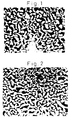
- Fig. 1 is an electron microscopic photograph of the microstructure in the cross-section perpendicular to the direction of solidification of the solidified body, in which the white portion is a GdAlO 3 phase and the black portion is an ⁇ -Al 2 O 3 phase. It was confirmed from Fig. 1 that the solidified body had a uniform structure having no colonies or grain boundaries and no pores or voids.
- Fig. 2 shows an electron microscopic photograph of the thus obtained solidified body consisting only of the GdAlO 3 phase which was three dimensionally continuous.
- the solidified body was a ceramic composite material having a microstructure consisting of two phases of an ⁇ -Al 2 O 3 single crystal and a CdAlO 3 single crystal which were three dimensionally continuous and intertwined with each other.
- Table 2 shows the mechanical strength of the ceramic composite material.
- the mechanical strength shown in Table 2 is the value measured by the three point flexural test at 1600°C in air.
- Fig. 3 shows the displacement curve of the flexural test in the longitudinal direction at 1600°C.
- Fig. 3 shows that the composite material exhibited a high yield of 700 MPa and upon yield it was not fractured but exhibited a plastic deformation.
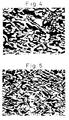
- Fig. 4 shows an electron microscopic photograph of the microstructure of the solidified body before the flexural test and Fig. 5 shows that after the flexural test at 1600°C. The photographs show that the ⁇ -Al 2 O 3 and GdAlO 3 phases were plastically deformed.
- Example No. Bending strength at 1600°C (MPa) Example 1 700 Com. Ex. 1 600 Com. Ex. 2 650
- the obtained mixed powder was charged in a molybdenum crucible set in a chamber, the atmospheric pressure in the chamber was kept to 10 -5 Torr, and the crucible was heated to 1850 to 1950°C by a high frequency coil to melt the mixed powder.
- the crucible was then lowered at such a rate that the cooling rate was 300°C/hr, while the atmospheric pressure in the chamber was kept to 10 -5 Torr, by which the unidirectional solidification was conducted to obtain a solidified body.
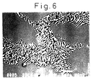
- Fig. 6 is an electron microscopic photograph of the microstructure in the cross-section perpendicular to the direction of solidification of the solidified body, in which the white portion is a GdAlO 3 phase and the black portion is an Al 2 O 3 phase. It was confirmed from Fig. 6 that the solidified body had a non-uniform structure having colonies and grain boundaries.
- the X-ray diffraction of the cross-section of the solidified body perpendicular to the direction of solidification thereof was taken.
- diffraction peaks from a plurality of planes of ⁇ -Al 2 O 3 and diffraction peaks from a plurality of planes of GdAlO 3 were observed and it was confirmed that the solidified body was a ceramic composite material consisting of two phases of an ⁇ -Al 2 O 3 polycrystal and a GdAlO 3 polycrystal.
- Table 2 shows the mechanical strength of this ceramic composite material.
- the mechanical strength shown in Table 2 is the value measured by the three point flexural test at 1600°C in air.
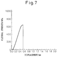
- Fig. 7 shows the stress-deformation curve of the flexural test at 1600°C.
- Fig. 7 shows that the composite material exhibited a high yield of 600 MPa but upon yield it was fractured without plastic deformation.
- Example 1 The procedures of Example 1 were repeated but the purification treatment by the zone melting method was not conducted and the crucible was lowered in such a rate that the cooling rate was 60°C/hr, while the atmospheric pressure in the chamber was kept to 10 -5 Torr, by which the unidirectional solidification was conducted to obtain a solidified body.
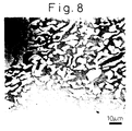
- Fig. 8 is an electron microscopic photograph of the microstructure in the cross-section perpendicular to the direction of solidification of the solidified body, in which the white portion is a GdAlO 3 phase and the black portion is an Al 2 O 3 phase. It was confirmed from Fig. 8 that the solidified body had a uniform structure having no colonies or grain boundaries and no pores or voids.
- the X-ray diffraction of the cross-section of the solidified body perpendicular to the direction of solidification thereof was taken.
- the solidified body was a ceramic composite material consisting of two phases of an ⁇ -Al 2 O 3 single crystal and a GdAlO 3 single crystal.
- Table 2 shows the mechanical strength of this ceramic composite material.
- the mechanical strength shown in Table 2 is the value measured by the three point flexural test at 1600°C in air.
- Fig. 9 shows the stress-deformation curve of the flexural test at 1600°C.
- Fig. 9 shows that the composite material exhibited a high yield of 650 MPa but brittle fracture occurred as can be seen in the curve of Fig. 9.
- Example 1 The procedures of Example 1 were repeated but the cooling rate was 100°C/hr, by which a solidified body was obtained.
- Fig. 10 is a SEM photograph of the microstructure in the cross-section perpendicular to the direction of solidification of the solidified body, in which the white portion is a GdAlO 3 phase and the black portion is an Al 2 O 3 phase. It was confirmed from Fig. 8 that the solidified body had a uniform structure having no colonies or grain boundaries and no pores or voids.
- the X-ray diffraction of the cross-section of the solidified body perpendicular to the direction of solidification thereof was taken.
- one diffraction peak from a specific plane of ⁇ -Al 2 O 3 and diffraction peaks from a plurality of planes of GdAlO 3 were observed and it was confirmed that the solidified body was a ceramic composite material consisting of two phases of an ⁇ -Al 2 O 3 single crystal and a GdAlO 3 polycrystal.
- Table 3 shows the mechanical strength of this ceramic composite material.
- the mechanical strength shown in Table 3 is the value measured by the three point flexural test at 1650°C in air.
- Fig. 11 shows the stress-deformation curve of the flexural test at 1650°C. Fig. 11 shows that the composite material exhibited a high yield of about 700 MPa and upon yield it was not fractured but exhibited a plastic deformation.
- Example No. Flexural strength at 1650°C (MPa) Example 2 700
- Example 1 The procedures of Example 1 were repeated but the cooling rate was 140°C/hr, by which a solidified body was obtained.
- Fig. 12 is an electron microscopic photograph of the microstructure in the cross-section perpendicular to the direction of solidification of the solidified body, in which the white portion is a GdAlO 3 phase and the black portion is an Al 2 O 3 phase. It was confirmed from Fig. 8 that the solidified body had a uniform structure having no colonies or grain boundaries and no pores or voids.
- the X-ray diffraction of the cross-section of the solidified body perpendicular to the direction of solidification thereof was taken.
- one diffraction peak from a specific plane of ⁇ -Al 2 O 3 and diffraction peaks from a plurality of planes of GdAlO 3 were observed and it was confirmed that the solidified body was a ceramic composite material consisting of two phases of an ⁇ -Al 2 O 3 single crystal and a GdAlO 3 polycrystal.
- Table 3 shows the mechanical strength of this ceramic composite material.
- the mechanical strength shown in Table 3 is the value measured by the three point flexural test at 1650°C in air.
- Fig. 13 shows the stress-deformation curve of the flexural test at 1650°C.
- Fig. 13 shows that the composite material exhibited a high yield of about 780 MPa and upon yielding it was not fractured but exhibited a plastic deformation.
- Example 1 The procedures of Example 1 were repeated but the cooling rate was 180°C/hr, by which a solidified body was obtained.
- Fig. 14 is an electron microscopic photograph of the microstructure in the cross-section perpendicular to the direction of solidification of the solidified body, in which the white portion is a GdAlO 3 phase and the black portion is an Al 2 O 3 phase. It was confirmed from Fig. 14 that the solidified body had a non-uniform structure having colonies and grain boundaries.
- the X-ray diffraction of the cross-section of the solidified body perpendicular to the direction of solidification thereof was taken.
- diffraction peaks from a plurality of planes of ⁇ -Al 2 O 3 and diffraction peaks from a plurality of planes of GdAlO 3 were observed and it was confirmed that the solidified body was a ceramic composite material consisting of two phases of an ⁇ -Al 2 O 3 polycrystal and a GdAlO 3 polycrystal.
- Table 3 shows the mechanical strength of this ceramic composite material.
- the mechanical strength shown in Table 3 is the value measured by the three point flexural test at 1650°C in air.
- Fig. 15 shows the stress-deformation curve of the flexural test at 1650°C.
- Fig. 15 shows that the composite material exhibited a high yield of 580 MPa but upon yield it was fractured without a plastic deformation.
- the obtained mixed powder was charged in a molybdenum crucible set in a chamber, the atmospheric pressure in the chamber was kept to 10 -5 Torr, and the crucible was heated to 1900 to 2000°C by a high frequency coil to melt the mixed powder.
- the crucible was then lowered at such a rate that the cooling rate was 50°C/hr, while the atmospheric pressure in the chamber was kept to 10 -5 Torr, by which the unidirectional solidification was conducted to obtain a solidified body.
- the solidified body with a diameter of 10 mm and a height of 50 mm was removed from the molybdenum crucible and then subjected to the zone melting method using a halogen lamp as a light source with a lowering speed of the solidified body of 10 mm/hr and a rotation speed of 2 rpm.
- the obtained solidified body and the starting powders were subjected to ICP analysis. The results are shown in Table 4.
- the starting powders contained some impurities in the order of about 200 ppm but each of the impurity levels was lowered to 100 ppm or less after the repeated zone melting.
- Compound Content (ppm) Starting powder Solidified body Dy 2 O 3 290 90 Ho 2 O 3 270 100 Er 2 O 3 260 85 Yb 2 O 3 240 100 SiO 2 235 50
- the thus purified solidified body was charged in a molybdenum crucible with the atmospheric pressure of 10 -5 Torr, and the crucible was heated to 1900 to 2000°C by a high frequency coil to melt the charged material. The crucible was then lowered at such a rate that the molten material was cooled at a cooling rate of 50°C/hr, to obtain a solidified body by unidirectional solidification.
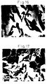
- Fig. 16 is an electron microscopic photograph of the microstructure in the cross-section perpendicular to the direction of solidification of the solidified body, in which the white portion is a YAG (yttrium aluminum garnet) phase and the black portion is an Al 2 O 3 phase. It was confirmed from Fig. 16 that the solidified body had a uniform structure having no colonies or grain boundaries and no pores or voids.
- YAG yttrium aluminum garnet
- the X-ray diffraction of the cross-section of the solidified body perpendicular to the direction of solidification thereof was taken.
- the solidified body was a ceramic composite material consisting of an ⁇ -Al 2 O 3 single crystal and a YAG single crystal.
- Fig. 17 shows an electron microscopic photograph of the thus obtained solidified body consisting only of the YAG phase which was three dimensionally continuous.
- the solidified body was a ceramic composite material having a microstructure consisting of two phases of ⁇ -Al 2 O 3 and YAG single crystal phases which were three dimensionally continuous and intertwined with each other.
- Table 5 shows the tensile strength of the ceramic composite material in air at a temperature from room temperature to 1750°C. The direction of tension applied to the sample was parallel to the direction of the unidirectional solidification.
- Fig. 18 shows the temperature dependency of the stress-deformation curve of the tensile test.
- Fig. 18 shows that the ⁇ -Al 2 O 3 /YAG composite material exhibited a brittle fracture up to 1600°C; a yielding appeared at 1650°C or more, clearly showing a plastic deformation; and the composite material exhibited an elongation of about 10% at 1700°C.
- Fig. 19 shows an electron microscopic photograph of the microstructure of the solidified body in parallel with the applied tension after the tensile test at 1650°C.
- Fig. 20 shows an electron microscopic photograph of a section of the sample fractured by the tensile test at 1700°C.
- the obtained mixed powder was charged in a molybdenum crucible set in a chamber, the atmospheric pressure in the chamber was kept to 10 -5 Torr, and the crucible was heated to 1900 to 2000°C by a high frequency coil to melt the mixed powder.
- the crucible was then lowered at such a rate that the cooling rate was 50°C/hr, while the atmospheric pressure in the chamber was kept to 10 -5 Torr, by which the unidirectional solidification was conducted to obtain a solidified body.
- the obtained solidified body and the starting powders were subjected to ICP analysis. The results are shown in Table 6.
- the starting powders contained some impurities in the order of about 200 ppm but each of the impurity levels was lowered to some extent.
- Compound Content (ppm) Starting powder Solidified body Dy 2 O 3 290 240 Ho 2 O 3 270 210 Er 2 O 3 260 225 Yb 2 O 3 240 200 SiO 2 235 210
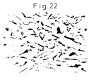
- Fig. 21 is an electron microscopic photograph of the microstructure in the cross-section perpendicular to the direction of solidification of the solidified body, in which the white portion is a YAG phase and the black portion is an ⁇ -Al 2 O 3 phase. It was confirmed from Fig. 21 that the solidified body had a uniform structure having no colonies or grain boundaries and no pores or voids.
- the solidified body was a ceramic composite material having a microstructure consisting of two phases of ⁇ -Al 2 O 3 single crystal and YAG single crystal which were three dimensionally continuous and, in a complex manner, intertwined with each other.
- Table 7 shows the tensile strength of the ceramic composite material in air at a temperature from room temperature to 1750°C. The direction of tension applied to the sample was parallel to the unidirectional solidification.
- Fig. 23 shows the temperature dependency of the stress-deformation curve of the tensile test. Fig. 23 shows that the ⁇ -Al 2 O 3 /YAG composite material exhibited a brittle fracture from room temperature to 1750°C. Test temperature (°C) Tensile strength (MPa) Room temperature 250 1600 280 1650 200 1700 170 1750 140
- the obtained mixed powder was charged in a molybdenum crucible set in a chamber, the atmospheric pressure in the chamber was kept to 10 -5 Torr, and the crucible was heated to 1900 to 2000°C by a high frequency coil to melt the mixed powder.
- the crucible was then lowered in such a rate that the cooling rate was 50°C/hr, while the atmospheric pressure in the chamber was kept to 10 -5 Torr, by which the unidirectional solidification was conducted to obtain a solidified body.
- the solidified body with a diameter of 10 mm and a height of 50 mm was removed from the molybdenum crucible and then subjected to the zone melting method using a halogen lamp as a light source with a lowering speed of the solidified body of 10 mm/hr and a rotation speed of 2 rpm.
- the obtained solidified body and the starting powders were subjected to ICP analysis. The results are shown in Table 8.
- the starting powders contained some impurities in the order of about 200 ppm but each of the impurity levels was lowered to 100 ppm or less after the repeated zone molting.
- the thus purified solidified body was charged in a molybdenum crucible with the atmospheric pressure of 10 -5 Torr, and the crucible was heated to 1900 to 2000°C by a high frequency coil to melt the charged material. The crucible was then lowered in such a rate that the molten material was cooled at a cooling rate of 50°C/hr, to obtain a solidified body by unidirectional solidification.
- Fig. 24 is an electron microscopic photograph of the microstructure in the cross-section perpendicular to the direction of solidification of the solidified body, in which the light portion is an Er 3 Al 5 O 12 phase and the dark portion is an Al 2 O 3 phase. It was confirmed from Fig. 24 that the solidified body had a uniform structure having no colonies or grain boundaries and no pores or voids.
- the X-ray diffraction of the cross-section of the solidified body perpendicular to the direction of solidification thereof was taken. As a result, only one diffraction peak from a specific plane of ⁇ -Al 2 O 3 and one diffraction peak from a specific plane of Er 3 Al 5 O 12 were observed and it was confirmed that the solidified body was a ceramic composite material consisting of an ⁇ -Al 2 O 3 single crystal and an Er 3 Al 5 O 12 single crystal.
- Fig. 25 shows an electron microscopic photograph of the thus obtained solidified body consisting only of the Er 3 Al 5 O 12 phase which was three dimensionally continuous.
- the solidified body was a ceramic composite material having a microstructure consisting of two phases of ⁇ -Al 2 O 3 single crystal and Er 3 Al 5 O 12 single crystal which were three dimensionally continuous and in a complex manner intertwined with each other.
- the ⁇ -Al 2 O 3 /Er 3 Al 5 O 12 composite material produced by the unidirectional solidification method exhibited a plastic deformation at 1650°C or more, similar to the ⁇ -Al 2 O 3 /YAG composite material of Example 4.
- the obtained mixed powder was charged in a molybdenum crucible set in a chamber, the atmospheric pressure in the chamber was kept to 10 -5 Torr, and the crucible was heated to 1900 to 2000°C by a high frequency coil to melt the mixed powder.
- the crucible was then lowered at such a rate that the cooling rate was 50°C/hr, while the atmospheric pressure in the chamber was kept to 10 -5 Torr, by which the unidirectional solidification was conducted to obtain a solidified body.
- the solidified body with a diameter of 10 mm and a height of 50 mm was removed from the molybdenum crucible and then subjected to the zone melting method using a halogen lamp as a light source with a lowering speed of the solidified body of 10 mm/hr and a rotation speed of 2 rpm.
- the obtained solidified body and the starting powders were subjected to ICP analysis.
- the results are shown in Table 4.
- the starting powders contained some impurities in the order of about 200 ppm but each of the impurity levels was lowered to 100 ppm or less after the repeated zone melting.
- the thus purified solidified body was charged in a molybdenum crucible with the atmospheric pressure of 10 -5 Torr, and the crucible was heated to 1900 to 2000°C by a high frequency coil to melt the charged material. The crucible was then lowered in such a rate that the molten material was cooled at a cooling rate of 50°C/hr, to obtain a solidified body by unidirectional solidification.
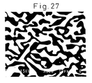
- Fig. 26 is an electron microscopic photograph of the microstructure in the cross-section perpendicular to the direction of solidification of the solidified body, in which the white portion is a YAG phase and the black portion is an Al 2 O 3 phase. It was confirmed from Fig. 26 that the solidified body had a uniform structure having no colonies or grain boundaries and no pores or voids.
- the ⁇ -Al 2 O 3 /YAG composite material produced by the unidirectional solidification method exhibited an extremely excellent microstructure stability at a high temperature as 1700°C, and exhibited substantially no weight change before and after said heat treatment.
- Example 1 As shown in the SEM photograph in Fig. 1, the solidified body produced in Example 1 had a uniform microstructure having no colonies or grain boundaries and no pores or voids. The X-ray diffraction of the cross-section of the solidified body perpendicular to the direction of solidification thereof showed that the solidified body was a ceramic composite material consisting of two phases of an ⁇ -Al 2 O 3 single crystal and a GdAlO 3 single crystal.
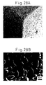
- Figs. 28A and 28B show SEM photographs of the thus obtained solidified body consisting only of the GdAlO 3 phase.
- Fig. 28A is a perspective view of a sample having a rectangular shape from a corner direction and Fig. 28B is an enlarged view of Fig. 28A.
- Fig. 28B clearly shows that the structure consisting of the GdAlO 3 phase and the pores intertwined with each other is a three dimensional structure.
- the solidified body was a ceramic composite material having a microstructure consisting of two phases of ⁇ -Al 2 O 3 single crystal and GdAlO 3 single crystal which were three dimensionally continuous and intertwined with each other, and, after removal of ⁇ -Al 2 O 3 , was a porous single crystal GdAlO 3 ceramic material having a network structure in which the GdAlO 3 phase was three dimentionally continuous.
- Table 10 shows the mechanical strength and porosity of this porous ceramic material.
- the mechanical strength shown in Table 10 is the values measured by the three point flexural test at room temperature in argon and at 1950°C in air.
- the porous ceramic material of this Example had a high flexural strength of 250 MPa even at 1950°C even though it had a high porosity of 60%. Further, the porosity and the flexural strength of the material were not changed after heat treatment in air at 1800°C for 100 hours.
- Example 2 This Example followed Example 2 in which the cooling rate was 100°C/hr.
- the solidified body produced in Example 2 had a uniform microstructure having no colonies or grain boundaries and no pores or voids.
- the X-ray diffraction of the cross-section of the solidified body perpendicular to the direction of solidification thereof showed that the solidified body was a ceramic composite material consisting of two phases of an ⁇ -Al 2 O 3 single crystal and a GdAlO 3 polycrystal.
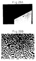
- Figs. 29A and 29B show SEM photographs of the thus obtained solidified body consisting only of the GdAlO 3 phase.
- Fig. 29A is a perspective view of a sample having a rectangular shape from a corner direction and Fig. 29B is an enlarged view of the portion indicated by the arrow in Fig. 29A.
- Fig. 29B clearly shows that the structure consisting of the GdAlO 3 phase and the pores intertwined with each other is a three dimensional structure.
- the solidified body was a ceramic composite material having a microstructure consisting of two phases of ⁇ -Al 2 O 3 single crystal and GdAlO 3 polycrystal which were three dimensionally continuous and intertwined with each other, and, after removal of ⁇ -Al 2 O 3 , was a porous polycrystal GdAlO 3 ceramic material having a network structure in which the GdAlO 3 phase was three dimensionally continuous.
- Table 10 shows the mechanical strength and porosity of this porous ceramic material.
- the mechanical strength shown in Table 10 is the value measured by the three point flexural test at room temperature in argon and at 1950°C in air.
- the porous ceramic material of this Example had a high flexural strength of 200 MPa at 1950°C even though it had a high porosity of 58%. Further, the porosity and the flexural strength of the material were not changed after heat treatment in air at 1800°C for 100 hours.
- the obtained mixed powder was charged in a graphite die and sintered, while pressing at a pressure of 500 kg/mm 2 , at a temperature of 1680°C and under an atmospheric pressure of 10 -2 Torr for 2 hours.
- the sintered body was a ceramic composite material consisting of an ⁇ -Al 2 O 3 polycrystal and a GdAlO 3 polycrystal.
- the sintered body was then immersed in an aqueous solution of nitric acid and fluoric acid in a weight % ratio of 1:5 for 20 hours to remove only the ⁇ -Al 2 O 3 .
- Table 11 shows the mechanical strength of the thus obtained porous sintered GdAlO 3 material consisting only of the GdAlO 3 phase.
- the mechanical strength shown in Table 11 is the value measured by the three point flexural test in air at room temperature. The mechanical strength is only 35 MPa. The flexural strength at 1950°C could not be measured since the sample did not keep its shape at that temperature.
- Example 4 Example 4 in which an ⁇ -Al 2 O 3 powder and a Y 2 O 3 powder were the starting powders.
- the solidified body produced in Example 4 had a uniform microstructure having no colonies or grain boundaries and no pores or voids.
- the X-ray diffraction of the cross-section of the solidified body perpendicular to the direction of solidification thereof showed that the solidified body was a ceramic composite material consisting of two phases of an ⁇ -Al 2 O 3 single crystal and a YAG single crystal.
- Figs. 30A and 30B show SEM photographs of the thus obtained solidified body consisting only of the GdAlO 3 phase.
- Fig. 30A is a perspective view of a sample having a rectangular shape from a corner direction and Fig. 30B is an enlarged view of the portion indicated by the arrow in Fig. 30A.
- Fig. 30B clearly shows that the structure consisting of the GdAlO 3 phase and the pores intertwined with each other is a three dimensional structure.
- the solidified body was a ceramic composite material having a microstructure consisting of two phases of ⁇ -Al 2 O 3 single crystal and YAG single crystal which were three dimensionally continuous and intertwined with each other, and, after removal of ⁇ -Al 2 O 3 , was a porous single crystal YAG ceramic material.
- Table 12 shows the mechanical strength and porosity of this porous ceramic material.
- the mechanical strength shown in Table 12 is the value measured by the three point flexural test in argon at room temperature and at 1900°C in air.
- the porous ceramic material of this Example had a high flexural strength of 170 MPa at 1900°C even though it had a high porosity of 55%. Further, the porosity and the flexural strength of the material were not changed after heat treatment in air at 1800°C for 100 hours.
- Example 9 55 175 170
- the obtained mixed powder was charged in a molybdenum crucible set in a chamber, the atmospheric pressure in the chamber was kept to 10 -5 Torr, and the crucible was heated to 1900 to 2000°C by a high frequency coil to melt the mixed powder.
- the crucible was then lowered at such a rate that the cooling rate was 50°C/hr, while the atmospheric pressure in the chamber was kept to 10 -5 Torr, by which the unidirectional solidification was conducted to obtain a solidified body.
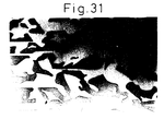
- Fig. 31 is a SEM photograph of the microstructure in the cross-section perpendicular to the direction of solidification of the solidified body, in which the light portion is an Er 3 Al 5 O 12 phase and the dark portion is an ⁇ -Al 2 O 3 phase. It was confirmed from Fig. 31 that the solidified body had a uniform structure having no colonies or grain boundaries and no pores or voids.
- the solidified body was a ceramic composite material having a microstructure consisting of two phases of single crystal ⁇ -Al 2 O 3 and single crystal Er 3 Al 5 O 12 which are three dimensionally continuous and intertwined with each other.
- Figs. 32A and 32B show SEM photographs of the thus obtained solidified body consisting only of the Er 3 Al 5 O 12 phase.
- Fig. 32A is a perspective view of a sample having a rectangular shape from a corner direction and Fig. 32B is an enlarged view of the portion indicated by the arrow in Fig. 32A.
- Fig. 32B clearly shows that the structure consisting of the GdAlO 3 phase and the pores intertwined with each other is a three dimensional structure.
- the solidified body was a ceramic composite material having a microstructure consisting of two phases of ⁇ -Al 2 O 3 single crystal and Er 3 Al 5 O 12 single crystal which were three dimensionally continuous and intertwined with each other, and, after removal of ⁇ -Al 2 O 3 , was a porous single crystal Er 3 Al 5 O 12 ceramic material.
- Table 12 shows the mechanical strength and porosity of this porous ceramic material.
- the mechanical strength shown in Table 12 is the value measured by the three point flexural test in argon at room temperature and at 1900°C in air.
- the porous ceramic material of this Example had a high flexural strength of 165 MPa at 1900°C even though it had a high porosity of 45%. Further, the porosity and the flexural strength of the material were not changed after heat treatment in air at 1800°C for 100 hours.
- the obtained mixed powder was charged in a graphite die and sintered, while pressing at a pressure of 500 kg/mm 2 , at a temperature of 1700°C and under an atmospheric pressure of 10 -2 Torr for 2 hours.
- the sintered body was a ceramic composite material consisting of an ⁇ -Al 2 O 3 polycrystal and a YAG polycrystal.
- the sintered body was then immersed in an aqueous solution of nitric acid and fluoric acid in a weight % ratio of 1:5 for 20 hours to remove only the ⁇ -Al 2 O 3 .
- Table 11 shows the mechanical strength and porosity of the thus obtained porous sintered YAG material consisting only of the YAG phase.
- the mechanical strength shown in Table 11 is the value measured by the three point flexural test in air at room temperature. The mechanical strength is only 30 MPa. The flexural strength at 1900°C could not be measured since the sample did not keep its shape at that temperature.
- the obtained mixed powder was charged in a graphite die and sintered, while pressing at a pressure of 500 kg/mm 2 , at a temperature of 1700°C and in an atmospheric pressure of 10 -2 Torr for 2 hours.
- the sintered body was a ceramic composite material consisting of an ⁇ -Al 2 O 3 polycrystal and an Er 3 Al 5 O 12 polycrystal.
- the sintered body was then immersed in an aqueous solution of nitric acid and fluoric acid in a weight % ratio of 1:5 for 20 hours to remove only the ⁇ -Al 2 O 3 .
- Table 11 shows the mechanical strength and porosity of the thus obtained porous sintered Er 3 Al 5 O 12 material consisting only of the Er 3 Al 5 O 12 phase.
- the mechanical strength shown in Table 11 is the value measured by the three point flexural test in air at room temperature. The mechanical strength is only 27 MPa. The flexural strength at 1900°C could not be measured since the sample did not keep its shape at that temperature.
Landscapes
- Chemical & Material Sciences (AREA)
- Engineering & Computer Science (AREA)
- Ceramic Engineering (AREA)
- Organic Chemistry (AREA)
- Materials Engineering (AREA)
- Structural Engineering (AREA)
- Crystallography & Structural Chemistry (AREA)
- Metallurgy (AREA)
- Manufacturing & Machinery (AREA)
- Inorganic Chemistry (AREA)
- Composite Materials (AREA)
- Compositions Of Oxide Ceramics (AREA)
- Crystals, And After-Treatments Of Crystals (AREA)
- Porous Artificial Stone Or Porous Ceramic Products (AREA)
- Filtering Materials (AREA)
Applications Claiming Priority (6)
| Application Number | Priority Date | Filing Date | Title |
|---|---|---|---|
| JP18804196 | 1996-07-01 | ||
| JP18804196A JP3743462B2 (ja) | 1996-07-01 | 1996-07-01 | セラミックス複合材料 |
| JP188041/96 | 1996-07-01 | ||
| JP238640/96 | 1996-08-22 | ||
| JP23864096 | 1996-08-22 | ||
| JP23864096A JP3405083B2 (ja) | 1996-08-22 | 1996-08-22 | 多孔質セラミックス材料 |
Publications (3)
| Publication Number | Publication Date |
|---|---|
| EP0816537A2 true EP0816537A2 (de) | 1998-01-07 |
| EP0816537A3 EP0816537A3 (de) | 2000-03-15 |
| EP0816537B1 EP0816537B1 (de) | 2004-11-10 |
Family
ID=26504706
Family Applications (1)
| Application Number | Title | Priority Date | Filing Date |
|---|---|---|---|
| EP97110754A Expired - Lifetime EP0816537B1 (de) | 1996-07-01 | 1997-07-01 | Keramisches Verbundmaterial und poröses keramisches Material |
Country Status (4)
| Country | Link |
|---|---|
| US (1) | US5981415A (de) |
| EP (1) | EP0816537B1 (de) |
| CN (1) | CN1211312C (de) |
| DE (1) | DE69731506T2 (de) |
Cited By (14)
| Publication number | Priority date | Publication date | Assignee | Title |
|---|---|---|---|---|
| WO2000058235A1 (fr) * | 1999-03-29 | 2000-10-05 | Sumitomo Coal Mining Co., Ltd. | Procede de preparation de ceramiques eutectiques |
| WO2002001622A3 (en) * | 2000-06-26 | 2002-04-11 | Univ North Carolina State | Novel non-crystalline oxides for use in microelectronic, optical, and other applications |
| WO2004065324A1 (ja) * | 2003-01-20 | 2004-08-05 | Ube Industries, Ltd. | 光変換用セラミックス複合材料およびその用途 |
| WO2006097876A1 (en) * | 2005-03-14 | 2006-09-21 | Koninklijke Philips Electronics N.V. | Phosphor in polycrystalline ceramic structure and a light-emitting element comprising same |
| EP1837921A4 (de) * | 2004-12-17 | 2009-12-30 | Ube Industries | Lichtumsetzungsstruktur und licht emittierendes bauelement damit |
| WO2010100103A1 (de) | 2009-03-03 | 2010-09-10 | Basf Se | Verfahren zur herstellung von polymermischungen |
| EP1760794A4 (de) * | 2004-06-24 | 2010-11-17 | Ube Industries | Weisses licht emittierendes diodenbauelement |
| WO2011045293A1 (de) | 2009-10-15 | 2011-04-21 | Basf Se | Verfahren zur kontinuierlichen herstellung von polyestermischungen |
| EP2000829A4 (de) * | 2006-03-30 | 2012-01-04 | Ube Industries | Lichtübertragungsstreuungsmaterial und seine verwendung |
| WO2012019868A2 (de) | 2010-07-19 | 2012-02-16 | Basf Se | Verfahren zur erhöhung des molekulargewichts von polyestern |
| EP1980606A4 (de) * | 2006-01-19 | 2012-05-23 | Ube Industries | Keramikverbundlichtumwandlungsglied und davon gebrauch machende leuchtvorrichtung |
| WO2016135057A1 (de) | 2015-02-27 | 2016-09-01 | Leuchtstoffwerk Breitungen Gmbh | Leuchtstoffkompositkeramik sowie verfahren zu deren herstellung |
| DE102017128847A1 (de) | 2016-12-08 | 2018-06-14 | Basf Se | Biologisch abbaubare Fußbekleidung basierend auf Polymilchsäure |
| EP3636403A4 (de) * | 2017-07-14 | 2021-03-17 | Canon Kabushiki Kaisha | Pulver zur keramischen formung, keramischer formkörper und verfahren zur herstellung davon |
Families Citing this family (68)
| Publication number | Priority date | Publication date | Assignee | Title |
|---|---|---|---|---|
| US6933331B2 (en) | 1998-05-22 | 2005-08-23 | Nanoproducts Corporation | Nanotechnology for drug delivery, contrast agents and biomedical implants |
| US6716525B1 (en) * | 1998-11-06 | 2004-04-06 | Tapesh Yadav | Nano-dispersed catalysts particles |
| US6383964B1 (en) * | 1998-11-27 | 2002-05-07 | Kyocera Corporation | Ceramic member resistant to halogen-plasma corrosion |
| DE69920152T2 (de) * | 1998-12-21 | 2005-09-22 | Shin-Etsu Chemical Co., Ltd. | Korrosionbeständiges Mischoxidmaterial |
| JP4917230B2 (ja) * | 1999-12-23 | 2012-04-18 | ダウ グローバル テクノロジーズ エルエルシー | 触媒装置 |
| US6669749B1 (en) * | 2000-02-02 | 2003-12-30 | 3M Innovative Properties Company | Fused abrasive particles, abrasive articles, and methods of making and using the same |
| US6607570B1 (en) * | 2000-02-02 | 2003-08-19 | 3M Innovative Properties Company | Fused Al2O3-rare earth oxide eutectic abrasive particles, abrasive articles, and methods of making and using the same |
| US6592640B1 (en) * | 2000-02-02 | 2003-07-15 | 3M Innovative Properties Company | Fused Al2O3-Y2O3 eutectic abrasive particles, abrasive articles, and methods of making and using the same |
| US6451077B1 (en) * | 2000-02-02 | 2002-09-17 | 3M Innovative Properties Company | Fused abrasive particles, abrasive articles, and methods of making and using the same |
| US6596041B2 (en) * | 2000-02-02 | 2003-07-22 | 3M Innovative Properties Company | Fused AL2O3-MgO-rare earth oxide eutectic abrasive particles, abrasive articles, and methods of making and using the same |
| US6645585B2 (en) * | 2000-05-30 | 2003-11-11 | Kyocera Corporation | Container for treating with corrosive-gas and plasma and method for manufacturing the same |
| US6458731B1 (en) | 2000-07-19 | 2002-10-01 | 3M Innovative Properties Company | Fused aluminum oxycarbide/nitride-AL2O3.Y2O3 eutectic materials |
| US6589305B1 (en) | 2000-07-19 | 2003-07-08 | 3M Innovative Properties Company | Fused aluminum oxycarbide/nitride-Al2O3 • rare earth oxide eutectic abrasive particles, abrasive articles, and methods of making and using the same |
| US6666750B1 (en) | 2000-07-19 | 2003-12-23 | 3M Innovative Properties Company | Fused AL2O3-rare earth oxide-ZrO2 eutectic abrasive particles, abrasive articles, and methods of making and using the same |
| US7384438B1 (en) * | 2000-07-19 | 2008-06-10 | 3M Innovative Properties Company | Fused Al2O3-Y2O3-ZrO2 eutectic abrasive particles, abrasive articles, and methods of making and using the same |
| US6583080B1 (en) | 2000-07-19 | 2003-06-24 | 3M Innovative Properties Company | Fused aluminum oxycarbide/nitride-Al2O3·rare earth oxide eutectic materials |
| US6582488B1 (en) * | 2000-07-19 | 2003-06-24 | 3M Innovative Properties Company | Fused Al2O3-rare earth oxide-ZrO2 eutectic materials |
| US6454822B1 (en) | 2000-07-19 | 2002-09-24 | 3M Innovative Properties Company | Fused aluminum oxycarbide/nitride-Al2O3·Y2O3 eutectic abrasive particles, abrasive articles, and methods of making and using the same |
| US6620756B2 (en) * | 2001-06-20 | 2003-09-16 | Ues, Inc. | Ceramic matrix composite cutting tool material |
| EP1412295B1 (de) | 2001-08-02 | 2007-11-14 | 3M Innovative Properties Company | Verfahren zur herstellung von gegenständen aus glas sowie so hergestellte glaskeramikgegenstände |
| KR100885329B1 (ko) | 2001-08-02 | 2009-02-26 | 쓰리엠 이노베이티브 프로퍼티즈 컴파니 | Al₂O₃-희토류 산화물-ZrO₂/HfO₂물질, 및그의 제조 및 사용 방법 |
| US7625509B2 (en) | 2001-08-02 | 2009-12-01 | 3M Innovative Properties Company | Method of making ceramic articles |
| WO2003104161A2 (en) * | 2001-08-02 | 2003-12-18 | 3M Innovative Properties Company | Alumina-yttria-zirconium oxide/hafnium oxide materials, and methods of making and using the same |
| US7510585B2 (en) | 2001-08-02 | 2009-03-31 | 3M Innovative Properties Company | Ceramic materials, abrasive particles, abrasive articles, and methods of making and using the same |
| US7563294B2 (en) * | 2001-08-02 | 2009-07-21 | 3M Innovative Properties Company | Abrasive particles and methods of making and using the same |
| US6855426B2 (en) | 2001-08-08 | 2005-02-15 | Nanoproducts Corporation | Methods for producing composite nanoparticles |
| US7098470B2 (en) | 2001-12-04 | 2006-08-29 | Landauer, Inc. | Method for non-destructive measuring of radiation dose |
| DE60228314D1 (de) * | 2001-12-04 | 2008-09-25 | Landauer Inc | Aluminiumoxidwerkstoff für die optische datenspeicherung |
| US7179526B2 (en) | 2002-08-02 | 2007-02-20 | 3M Innovative Properties Company | Plasma spraying |
| US8056370B2 (en) | 2002-08-02 | 2011-11-15 | 3M Innovative Properties Company | Method of making amorphous and ceramics via melt spinning |
| US7708974B2 (en) | 2002-12-10 | 2010-05-04 | Ppg Industries Ohio, Inc. | Tungsten comprising nanomaterials and related nanotechnology |
| US7811496B2 (en) | 2003-02-05 | 2010-10-12 | 3M Innovative Properties Company | Methods of making ceramic particles |
| US7175786B2 (en) | 2003-02-05 | 2007-02-13 | 3M Innovative Properties Co. | Methods of making Al2O3-SiO2 ceramics |
| US6984261B2 (en) * | 2003-02-05 | 2006-01-10 | 3M Innovative Properties Company | Use of ceramics in dental and orthodontic applications |
| US7258707B2 (en) | 2003-02-05 | 2007-08-21 | 3M Innovative Properties Company | AI2O3-La2O3-Y2O3-MgO ceramics, and methods of making the same |
| US7292766B2 (en) | 2003-04-28 | 2007-11-06 | 3M Innovative Properties Company | Use of glasses containing rare earth oxide, alumina, and zirconia and dopant in optical waveguides |
| US7197896B2 (en) | 2003-09-05 | 2007-04-03 | 3M Innovative Properties Company | Methods of making Al2O3-SiO2 ceramics |
| EP1686107A4 (de) * | 2003-09-12 | 2008-12-03 | Ibiden Co Ltd | Keramiksinterkörper und keramikfilter |
| US7141522B2 (en) | 2003-09-18 | 2006-11-28 | 3M Innovative Properties Company | Ceramics comprising Al2O3, Y2O3, ZrO2 and/or HfO2, and Nb2O5 and/or Ta2O5 and methods of making the same |
| US7141523B2 (en) | 2003-09-18 | 2006-11-28 | 3M Innovative Properties Company | Ceramics comprising Al2O3, REO, ZrO2 and/or HfO2, and Nb2O5 and/or Ta2O5 and methods of making the same |
| US7297171B2 (en) | 2003-09-18 | 2007-11-20 | 3M Innovative Properties Company | Methods of making ceramics comprising Al2O3, REO, ZrO2 and/or HfO2 and Nb205 and/or Ta2O5 |
| US7497093B2 (en) * | 2004-07-29 | 2009-03-03 | 3M Innovative Properties Company | Method of making ceramic articles |
| US7332453B2 (en) * | 2004-07-29 | 2008-02-19 | 3M Innovative Properties Company | Ceramics, and methods of making and using the same |
| EP1811580A4 (de) * | 2004-10-21 | 2012-05-23 | Ube Industries | Leuchtdiodenelement, board für eine leuchtdiode und verfahren zur herstellung eines leuchtdiodenelements |
| CN100566490C (zh) * | 2005-03-14 | 2009-12-02 | 皇家飞利浦电子股份有限公司 | 多晶陶瓷结构中的磷光体和包括该磷光体的发光元件 |
| US7049548B1 (en) | 2005-03-21 | 2006-05-23 | The Boeing Company | System and method for processing a preform vacuum vessel to produce a structural assembly |
| US7431196B2 (en) | 2005-03-21 | 2008-10-07 | The Boeing Company | Method and apparatus for forming complex contour structural assemblies |
| US7621692B2 (en) * | 2005-04-29 | 2009-11-24 | Airostone Corp. | Porous ceramic paving material |
| DE102005023048B4 (de) * | 2005-05-13 | 2011-06-22 | Forschungszentrum Jülich GmbH, 52428 | Verfahren zur Herstellung eines Kathoden-Elektrolyt-Verbundes und eine Hochtemperatur-Brennstoffzelle |
| US7281970B2 (en) | 2005-12-30 | 2007-10-16 | 3M Innovative Properties Company | Composite articles and methods of making the same |
| US7598188B2 (en) | 2005-12-30 | 2009-10-06 | 3M Innovative Properties Company | Ceramic materials and methods of making and using the same |
| US7585772B2 (en) * | 2006-07-26 | 2009-09-08 | Freiberger Compound Materials Gmbh | Process for smoothening III-N substrates |
| JP5157909B2 (ja) * | 2006-09-25 | 2013-03-06 | 宇部興産株式会社 | 光変換用セラミックス複合体およびそれを用いた発光装置 |
| US7855163B2 (en) * | 2007-05-14 | 2010-12-21 | Geo2 Technologies, Inc. | Low coefficient of thermal expansion bonding system for a high porosity ceramic body and methods of manufacture |
| US7567817B2 (en) * | 2007-05-14 | 2009-07-28 | Geo2 Technologies, Inc. | Method and apparatus for an extruded ceramic biosoluble fiber substrate |
| US7781372B2 (en) | 2007-07-31 | 2010-08-24 | GE02 Technologies, Inc. | Fiber-based ceramic substrate and method of fabricating the same |
| BRPI0923723A2 (pt) * | 2008-12-31 | 2017-07-11 | Saint Gobain Ceramics | Artigo cerâmico e processo de produção do mesmo |
| CN101805175A (zh) * | 2010-04-06 | 2010-08-18 | 九江学院 | 一种钇铝石榴石多孔陶瓷及其制备方法 |
| CN102557593A (zh) * | 2010-12-21 | 2012-07-11 | 兰州理工大学 | YAG/Al2O3复相陶瓷材料及其制备方法 |
| CN103508746A (zh) * | 2012-06-18 | 2014-01-15 | 苏州忠辉蜂窝陶瓷有限公司 | 一种高净化率堇青石蜂窝陶瓷及其制备方法 |
| CN106029300B (zh) * | 2013-12-30 | 2019-06-28 | 圣戈班磨料磨具有限公司 | 复合体及其形成方法 |
| RU2569651C1 (ru) * | 2014-06-09 | 2015-11-27 | Федеральное государственное бюджетное образовательное учреждение высшего профессионального образования "РОССИЙСКИЙ ХИМИКО-ТЕХНОЛОГИЧЕСКИЙ УНИВЕРСИТЕТ имени Д.И.Менделеева" (РХТУ им. Д.И.Менделеева) | Способ получения керамических блочно-ячеистых фильтров-сорбентов для улавливания газообразного радиоактивного цезия |
| JP6608835B2 (ja) | 2014-09-25 | 2019-11-20 | 株式会社東芝 | 希土類蓄冷材粒子、それを用いた冷凍機、超電導磁石、検査装置およびクライオポンプ |
| US10593967B2 (en) | 2016-06-30 | 2020-03-17 | Honeywell International Inc. | Modulated thermal conductance thermal enclosure |
| CN113119391B (zh) | 2019-12-30 | 2023-03-17 | 荣耀终端有限公司 | 陶瓷树脂复合壳体及其制备方法和终端 |
| CN114804835A (zh) * | 2021-01-28 | 2022-07-29 | 上海上纳电工器材有限公司 | 一种新型碳复合陶瓷线性电阻及其制备方法 |
| CN113683420B (zh) * | 2021-07-27 | 2022-10-11 | 中国科学院金属研究所 | 一种大尺寸Al2O3/LuAG定向凝固共晶陶瓷及其光悬浮区熔制备方法 |
| CN120574049B (zh) * | 2025-07-09 | 2025-11-21 | 成都旭瓷新材料有限公司 | 一种高抗弯强度氮化铝陶瓷烧结体及其制备方法 |
Family Cites Families (9)
| Publication number | Priority date | Publication date | Assignee | Title |
|---|---|---|---|---|
| US4881951A (en) * | 1987-05-27 | 1989-11-21 | Minnesota Mining And Manufacturing Co. | Abrasive grits formed of ceramic containing oxides of aluminum and rare earth metal, method of making and products made therewith |
| JP2901303B2 (ja) * | 1990-02-08 | 1999-06-07 | イビデン株式会社 | 多孔質炭化珪素焼結体の製造方法 |
| JPH0431375A (ja) * | 1990-05-23 | 1992-02-03 | Matsushita Electric Ind Co Ltd | 多孔質耐熱材の製造方法 |
| JPH0465372A (ja) * | 1990-07-02 | 1992-03-02 | Saga Pref Gov | 高強度多孔質セラミックスの製造方法 |
| CA2102656A1 (en) * | 1992-12-14 | 1994-06-15 | Dwight D. Erickson | Abrasive grain comprising calcium oxide and/or strontium oxide |
| JP3216683B2 (ja) * | 1993-10-08 | 2001-10-09 | 宇部興産株式会社 | セラミックス複合材料 |
| JP3264106B2 (ja) * | 1993-11-12 | 2002-03-11 | 宇部興産株式会社 | セラミックス複合材料 |
| US5484752A (en) * | 1993-11-12 | 1996-01-16 | Ube Industries, Ltd. | Ceramic composite material |
| JP3128044B2 (ja) * | 1993-11-12 | 2001-01-29 | 宇部興産株式会社 | セラミックス複合材料 |
-
1997
- 1997-06-28 CN CNB971012008A patent/CN1211312C/zh not_active Expired - Fee Related
- 1997-06-30 US US08/885,568 patent/US5981415A/en not_active Expired - Lifetime
- 1997-07-01 EP EP97110754A patent/EP0816537B1/de not_active Expired - Lifetime
- 1997-07-01 DE DE69731506T patent/DE69731506T2/de not_active Expired - Lifetime
Cited By (24)
| Publication number | Priority date | Publication date | Assignee | Title |
|---|---|---|---|---|
| US6592798B1 (en) * | 1999-03-29 | 2003-07-15 | Mamoru Omori | Method for preparing eutectic ceramics |
| WO2000058235A1 (fr) * | 1999-03-29 | 2000-10-05 | Sumitomo Coal Mining Co., Ltd. | Procede de preparation de ceramiques eutectiques |
| WO2002001622A3 (en) * | 2000-06-26 | 2002-04-11 | Univ North Carolina State | Novel non-crystalline oxides for use in microelectronic, optical, and other applications |
| US6787861B2 (en) | 2000-06-26 | 2004-09-07 | North Carolina State University | Non-crystalline oxides for use in microelectronic, optical, and other applications |
| US8900480B2 (en) | 2003-01-20 | 2014-12-02 | Ube Industries, Ltd. | Ceramic composite material for light conversion and use thereof |
| WO2004065324A1 (ja) * | 2003-01-20 | 2004-08-05 | Ube Industries, Ltd. | 光変換用セラミックス複合材料およびその用途 |
| EP1760794A4 (de) * | 2004-06-24 | 2010-11-17 | Ube Industries | Weisses licht emittierendes diodenbauelement |
| EP1837921A4 (de) * | 2004-12-17 | 2009-12-30 | Ube Industries | Lichtumsetzungsstruktur und licht emittierendes bauelement damit |
| US8044572B2 (en) | 2004-12-17 | 2011-10-25 | Ube Industries, Ltd. | Light conversion structure and light-emitting device using the same |
| US7879258B2 (en) | 2005-03-14 | 2011-02-01 | Koninklijke Philips Electronics N.V. | Phosphor in polycrystalline ceramic structure and a light-emitting element comprising same |
| KR101370362B1 (ko) * | 2005-03-14 | 2014-03-05 | 코닌클리케 필립스 엔.브이. | 다결정 세라믹 구조 내의 인광체 및 이를 포함하는 발광 요소 |
| WO2006097876A1 (en) * | 2005-03-14 | 2006-09-21 | Koninklijke Philips Electronics N.V. | Phosphor in polycrystalline ceramic structure and a light-emitting element comprising same |
| US8496852B2 (en) | 2005-03-14 | 2013-07-30 | Philips Koninklijke N.V. | Phosphor in polycrystalline ceramic structure and a light-emitting element comprisng same |
| EP1980606A4 (de) * | 2006-01-19 | 2012-05-23 | Ube Industries | Keramikverbundlichtumwandlungsglied und davon gebrauch machende leuchtvorrichtung |
| EP2000829A4 (de) * | 2006-03-30 | 2012-01-04 | Ube Industries | Lichtübertragungsstreuungsmaterial und seine verwendung |
| WO2010100103A1 (de) | 2009-03-03 | 2010-09-10 | Basf Se | Verfahren zur herstellung von polymermischungen |
| WO2011045293A1 (de) | 2009-10-15 | 2011-04-21 | Basf Se | Verfahren zur kontinuierlichen herstellung von polyestermischungen |
| WO2012019868A2 (de) | 2010-07-19 | 2012-02-16 | Basf Se | Verfahren zur erhöhung des molekulargewichts von polyestern |
| WO2016135057A1 (de) | 2015-02-27 | 2016-09-01 | Leuchtstoffwerk Breitungen Gmbh | Leuchtstoffkompositkeramik sowie verfahren zu deren herstellung |
| DE102015102842A1 (de) | 2015-02-27 | 2016-09-01 | Fraunhofer-Gesellschaft zur Förderung der angewandten Forschung e.V. | Leuchtstoffkompositkeramik sowie Verfahren zu deren Herstellung |
| DE102017128847A1 (de) | 2016-12-08 | 2018-06-14 | Basf Se | Biologisch abbaubare Fußbekleidung basierend auf Polymilchsäure |
| EP3636403A4 (de) * | 2017-07-14 | 2021-03-17 | Canon Kabushiki Kaisha | Pulver zur keramischen formung, keramischer formkörper und verfahren zur herstellung davon |
| US11718567B2 (en) | 2017-07-14 | 2023-08-08 | Canon Kabushiki Kaisha | Powder for ceramic manufacturing, ceramic manufactured object, and manufacturing method thereof |
| US12024469B2 (en) | 2017-07-14 | 2024-07-02 | Canon Kabushiki Ka Ha | Powder for ceramic manufacturing, ceramic manufactured object, and manufacturing method thereof |
Also Published As
| Publication number | Publication date |
|---|---|
| DE69731506D1 (de) | 2004-12-16 |
| US5981415A (en) | 1999-11-09 |
| CN1171379A (zh) | 1998-01-28 |
| DE69731506T2 (de) | 2005-10-20 |
| EP0816537B1 (de) | 2004-11-10 |
| EP0816537A3 (de) | 2000-03-15 |
| CN1211312C (zh) | 2005-07-20 |
Similar Documents
| Publication | Publication Date | Title |
|---|---|---|
| EP0816537B1 (de) | Keramisches Verbundmaterial und poröses keramisches Material | |
| US5902763A (en) | Fused ceramic composite | |
| EP0647601B1 (de) | Keramischer Verbundwerkstoff | |
| US4851375A (en) | Methods of making composite ceramic articles having embedded filler | |
| US5298470A (en) | Silicon carbide bodies having high toughness and fracture resistance and method of making same | |
| EP0654456A1 (de) | Keramischer Verbundwerkstoff | |
| US5334562A (en) | Composite ceramic articles | |
| JP2882575B2 (ja) | 高熱伝導窒化ケイ素セラミックスならびにその製造方法 | |
| JP3743462B2 (ja) | セラミックス複合材料 | |
| JP3412381B2 (ja) | セラミックス複合材料 | |
| JP2615437B2 (ja) | 高強度・高靱性窒化ケイ素焼結体及びその製造方法 | |
| WO2005049525A1 (ja) | 高熱伝導性窒化アルミニウム焼結体 | |
| EP0419271A2 (de) | Siliciumcarbidkörper mit grosser Zähigkeit und Bruchfestigkeit und Verfahren zu seiner Herstellung | |
| JP3412378B2 (ja) | セラミックス複合材料 | |
| Suzuki et al. | Mechanical properties of alkoxy-derived cordierite ceramics | |
| JP3412379B2 (ja) | セラミックス複合材料 | |
| JP3405083B2 (ja) | 多孔質セラミックス材料 | |
| JP3994879B2 (ja) | 多孔質セラミックス材料 | |
| JPH09208328A (ja) | 多孔質高強度低熱伝導窒化ケイ素質セラミックス及びその製造方法 | |
| JPH0375508B2 (de) | ||
| JP2895147B2 (ja) | 窒化アルミニウム複合焼結体 | |
| US5340515A (en) | Polycrystalline γ-lithium aluminate fibers and process of manufacture | |
| RU2096386C1 (ru) | Шихта для изготовления огнеупорных изделий | |
| JP3412380B2 (ja) | セラミックス複合材料 | |
| Kenawy | Synthesis Aluminum Borate Ceramic |
Legal Events
| Date | Code | Title | Description |
|---|---|---|---|
| PUAI | Public reference made under article 153(3) epc to a published international application that has entered the european phase |
Free format text: ORIGINAL CODE: 0009012 |
|
| AK | Designated contracting states |
Kind code of ref document: A2 Designated state(s): DE FR GB |
|
| PUAL | Search report despatched |
Free format text: ORIGINAL CODE: 0009013 |
|
| AK | Designated contracting states |
Kind code of ref document: A3 Designated state(s): AT BE CH DE DK ES FI FR GB GR IE IT LI LU MC NL PT SE |
|
| 17P | Request for examination filed |
Effective date: 20000802 |
|
| AKX | Designation fees paid |
Free format text: DE FR GB |
|
| 17Q | First examination report despatched |
Effective date: 20020418 |
|
| GRAP | Despatch of communication of intention to grant a patent |
Free format text: ORIGINAL CODE: EPIDOSNIGR1 |
|
| GRAS | Grant fee paid |
Free format text: ORIGINAL CODE: EPIDOSNIGR3 |
|
| RAP1 | Party data changed (applicant data changed or rights of an application transferred) |
Owner name: UBE INDUSTRIES, LTD. |
|
| GRAA | (expected) grant |
Free format text: ORIGINAL CODE: 0009210 |
|
| AK | Designated contracting states |
Kind code of ref document: B1 Designated state(s): DE FR GB |
|
| REG | Reference to a national code |
Ref country code: GB Ref legal event code: FG4D |
|
| REF | Corresponds to: |
Ref document number: 69731506 Country of ref document: DE Date of ref document: 20041216 Kind code of ref document: P |
|
| ET | Fr: translation filed | ||
| PLBE | No opposition filed within time limit |
Free format text: ORIGINAL CODE: 0009261 |
|
| STAA | Information on the status of an ep patent application or granted ep patent |
Free format text: STATUS: NO OPPOSITION FILED WITHIN TIME LIMIT |
|
| 26N | No opposition filed |
Effective date: 20050811 |
|
| REG | Reference to a national code |
Ref country code: FR Ref legal event code: PLFP Year of fee payment: 19 |
|
| REG | Reference to a national code |
Ref country code: DE Ref legal event code: R082 Ref document number: 69731506 Country of ref document: DE Representative=s name: HOEGER, STELLRECHT & PARTNER PATENTANWAELTE MB, DE |
|
| PGFP | Annual fee paid to national office [announced via postgrant information from national office to epo] |
Ref country code: GB Payment date: 20150701 Year of fee payment: 19 Ref country code: DE Payment date: 20150624 Year of fee payment: 19 |
|
| PGFP | Annual fee paid to national office [announced via postgrant information from national office to epo] |
Ref country code: FR Payment date: 20150629 Year of fee payment: 19 |
|
| REG | Reference to a national code |
Ref country code: DE Ref legal event code: R119 Ref document number: 69731506 Country of ref document: DE |
|
| GBPC | Gb: european patent ceased through non-payment of renewal fee |
Effective date: 20160701 |
|
| PG25 | Lapsed in a contracting state [announced via postgrant information from national office to epo] |
Ref country code: FR Free format text: LAPSE BECAUSE OF NON-PAYMENT OF DUE FEES Effective date: 20160801 Ref country code: DE Free format text: LAPSE BECAUSE OF NON-PAYMENT OF DUE FEES Effective date: 20170201 |
|
| REG | Reference to a national code |
Ref country code: FR Ref legal event code: ST Effective date: 20170331 |
|
| PG25 | Lapsed in a contracting state [announced via postgrant information from national office to epo] |
Ref country code: GB Free format text: LAPSE BECAUSE OF NON-PAYMENT OF DUE FEES Effective date: 20160701 |