EP0816553A2 - Verfahren und Vorrichtung zum Zuführen von insbesondere Hosen zu einem Faltautomaten oder dergleichen - Google Patents
Verfahren und Vorrichtung zum Zuführen von insbesondere Hosen zu einem Faltautomaten oder dergleichen Download PDFInfo
- Publication number
- EP0816553A2 EP0816553A2 EP97109735A EP97109735A EP0816553A2 EP 0816553 A2 EP0816553 A2 EP 0816553A2 EP 97109735 A EP97109735 A EP 97109735A EP 97109735 A EP97109735 A EP 97109735A EP 0816553 A2 EP0816553 A2 EP 0816553A2
- Authority
- EP
- European Patent Office
- Prior art keywords
- pants
- folding
- wall
- lay
- folding machine
- Prior art date
- Legal status (The legal status is an assumption and is not a legal conclusion. Google has not performed a legal analysis and makes no representation as to the accuracy of the status listed.)
- Granted
Links
Images



Classifications
-
- D—TEXTILES; PAPER
- D06—TREATMENT OF TEXTILES OR THE LIKE; LAUNDERING; FLEXIBLE MATERIALS NOT OTHERWISE PROVIDED FOR
- D06F—LAUNDERING, DRYING, IRONING, PRESSING OR FOLDING TEXTILE ARTICLES
- D06F89/00—Apparatus for folding textile articles with or without stapling
- D06F89/02—Apparatus for folding textile articles with or without stapling of textile articles to be worn, e.g. shirts
Definitions
- the invention relates to a method for feeding especially trousers for a folding machine or the like according to the preamble of claim 1. Further relates to the invention provides a device for feeding in particular Pants to a folding machine or the like according to the Preamble of claim 7.
- the transport bracket is folded in Arms separated from the clothing and in the Work area of the folding machine transported where it be folded accordingly.
- the invention is based on the object, a method and a device for feeding pants in particular to one To create folding machines or the like, with which one Foldable trousers are guaranteed becomes.
- a procedure for solving this problem shows the measures of Claim 1 on.
- the fact that before folding the pants legs Pants at least partially overlapped, has been surprising shown that the pants folded afterwards did not just let it fold well; rather the ready-made pants too has good cohesion.
- the pants legs are during or if necessary even after placing the pants on the worktop of the Folding machine completely or partially overlapped.
- the pants then run with at least partially overlapping legs in the Folding area of the folding machine, whereby after folding the Practically "stitch" the trouser legs together.
- the pants so folded can be gripped by hand on one side without being on the other side falls apart.
- the crotch area of the pants i.e. the area of the same at which the two pants legs converge, raised, especially moved away from the contact surface.
- This raising the crotch area the pants are expediently such that at least the areas of the Pants legs in different, superimposed levels reach.
- This will overlap the pants legs supports and at the same time when the pants legs overlap resulting gusset in the crotch area stretched in a controlled manner.
- This by overlapping the pants legs resulting gusset in the crotch area of the pants is like this practically pre-folded, namely controlled on the rest Put part of the pants down before they hit the surface following folding area of the folding machine is folded.
- the pants especially when feeding from the work surface held down to the folding area of the folding machine.
- the pants are particularly pressed against the contact surface.
- longitudinal folds of the pants, especially the Pants legs, during the transport of the respective pants to Striped folding area are particularly pressed against the contact surface.
- the pants fixed by holding down on the contact surface thereby reliable removal of the transport bracket from the respective pants is guaranteed.
- a device for solving the basis of the invention Task has the features of claim 7. Accordingly assigned to the work surface means on which the trouser legs come to rest at least partially. The means are across Working direction of the folding machine can be moved, causing the pants legs can be at least partially overlapped.
- Each pant leg is preferably a corresponding agent assigned. It is also provided that the two are different Means associated with pant legs with a height offset to provide. This makes it possible for cross-processing of the means that a trouser leg at least partially over the other leg comes to rest. So that the pants legs Participate in the cross-procedure of the funds, i.e. in the cross-procedure cannot slide down from the means, they will Pants legs at least partially held on any means. This happens preferably by negative pressure, by means Suction organs are assigned to the areas of each trouser leg fix the appropriate agent.
- the contact surface one that can be engaged with a crotch area of the pants Tongue assigned.
- These are preferably vertical, but off-center, tongue extending to the contact surface serves to To raise the crotch area of the pants in relation to the contact surface, the areas of the trouser legs adjoining the crotch area get into different levels, which means that the said area of a pant leg is raised more than the corresponding area of the other leg. This will one when the pants legs overlap in the crotch area forming material accumulation avoided and the gusset tightened to avoid wrinkling in the crotch area.
- the tongue can be moved or swiveled perpendicular to the contact surface. When the pants are pulled onto the contact surface, the tongue stands over the same. In the further course of treatment of the The tongue can be retracted behind the contact surface.
- a folding means is provided in the area of the tongue. This is designed so that it from the tongue the level of the contact surface moved gusset in the Crotch area folded over after moving the tongue back and thereby the gusset to avoid uncontrolled wrinkles targeted to adjacent areas of the pants on the work surface creates.
- a pressure device is provided on the work surface assign.
- the pressure device is from the outside mobile on the pants placed on the work surface, so that the pants between the contact surface and the pressure device can be clamped. This will put the pants on the work surface held or fixed, especially for pulling out of the folded transport bracket from the pants. It will this ensures that when removing the transport bracket the pants remain on the contact surface and especially no folds when pulling out the transport bracket the pants arise.
- both the contact surface is provided having laying-on wall as well as the pressure device as Train sponsors.
- the sponsors of the dressing wall and the Pressure devices are preferably cyclical, namely at Need, drivable, and in particular synchronously, thereby the Pants tightened when feeding to the folding area of the folding machine is and thus wrinkling of the pants when feeding to Folding area can be avoided.
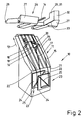
- FIG. 1 to 5 show part of a folding machine 10, namely the area of a contact surface 11 of the folding machine.
- a subsequent folding area of the Folding machine 10 is in the figures for reasons of simplification not shown.
- the folding machine 10 is used for folding Clothing, in particular work clothing. According to the folding machine 10 is in a special way Folding pants, especially dungarees 13, educated. In the following, the invention is therefore based on discussed in Fig. 2 to 5 dungarees 13, though the folding machine 10 is also suitable for folding other items of clothing, especially workwear.
- the dungarees 13 to be folded are placed on the folding machine 10 Hanging not supplied transport brackets.
- the transport bracket with the dungarees 13 attached to it are from one Transport system, one of which in FIGS. 1 to 5 as one Conveyor rail 14 formed conveyor track partially shown is transported to the folding machine 10 and here on the inclined support surface 11, which is part of a support wall 15 of the folding machine 10 is placed. After hanging up the Dungarees 13 on the support surface 11 of the support wall 15 the respective transport bracket folded and out of the dungarees 13 pulled out. Then the on the contact surface put on dungarees 13 from the lay-on wall 15 in the working direction 12 transported on to the subsequent folding area of the folding machine 10.
- the inclined wall 15 of the folding machine 10 is as rotating conveyor trained.
- this conveyor is formed by five at a distance narrow circumferential conveyor belts 16 which are arranged relative to one another. There are small gaps between adjacent conveyor belts 16 17 formed.
- the distribution of the conveyor belts 16 on the The contact surface 17 is symmetrical to the working direction 12 extending longitudinal central axis of the contact surface 11, that is, this longitudinal central axis runs through the longitudinal central axis of the central conveyor belt 16. All conveyor belts 16 are simultaneously drivable, in such a way that they are in Work direction 12 run.
- a step plate 18th acts in the space 17 next to the middle conveyor belt 16 and the adjacent conveyor belt 16 (in the embodiment shown to the right of the middle conveyor belt 16) in the embodiment shown to the right of the middle conveyor belt 16.
- the flat, off-center step plate 18 is located in a plane that is perpendicular to the plane of the laying wall 11 runs.
- the crotch plate 18 is in this vertical plane pivotable, in such a way that it is as shown 1, 4 and 5 behind the contact surface 11 of the Lay-on wall 15 is located.
- the crotch plate 18 In another position, namely in a working position, the crotch plate 18 is opposite Level of the contact surface 11 pivoted up by it partially protrudes from the level of the contact surface 11 upwards as it 2 and 3 show.
- the step plate 18 can be pivoted by one in the area of the upper edge of the crotch plate 18 arranged pivot axis, which is behind the contact surface 11 of the Lay-on wall 15 lies and therefore not visible in the figures is.
- Crotch plate 18 is designed such that it is in its 2 and 3 shown swiveled position with an approximately triangular section opposite the contact surface 11 protrudes.
- a shorter one, towards the lower end of the lay-on wall 15 facing section 19 of the crotch plate 18 is shown in FIG Embodiment approximately curved and runs almost perpendicular to the plane of the contact surface 11.
- a second, longer section 20 of the crotch plate 18 runs under one acute angle to the contact surface 11, in such a way that a to the shorter section 19, the end of the longer one Section 20 the largest survey compared to the contact area 11.
- the opposite end of the long section 20 intersects the plane of the contact surface 11 by being inside immersed.
- Cover wall extensions 23 made of vertical plates 24 formed by the drives, not shown, transversely to Working direction 12 of the folding machine 10 in front of the lay-on wall 15 are movable.
- the two widening walls are preferably widened 23 can be moved together or apart synchronously.
- the vertical plates 24 of the extension widening 23 are in a special relative arrangement in front of the lower end 21 the lay-on wall 15 is arranged. You are namely at one in two different, parallel to each other Levels so that the collapsed widening walls 23 by far partially overlapping plates 24 have.
- the plates 24 are vertical Height offset.
- the right plate 24 is shown in FIG Embodiment (Fig. 1) higher than the left plate 24. Die horizontal edges of the plates 24 are thereby on different height levels. This ensures that the lower ends of the legs 22 to overlap get (Fig. 2), so when moving the plates 24 together Pants legs 22 move over each other without colliding can.
- the plates 24 are the widening wall extensions 23 symmetrical to the longitudinal central axis of the folding machine 10 arranged. Also in FIG. 2, for example shown collapsed condition of the widening wall extensions 23, the plates 24 are symmetrical about the longitudinal central axis of the folding machine 10 or to the longitudinal central axis lying thereon of the middle conveyor belt 16.
- the widening wall extensions 23 are provided with means for holding formed by parts of the legs 22. These funds are (in Working direction 12 seen) on the front of the vertical Plates 24 arranged.
- the funds are suction devices 25 that are linear on a diagonal each Plate 24 run in such a way that the upper ends each line-like suction device 25 to the middle of the Folding machines 10 have.
- the folding machine 10 also has one above the Lay-on wall 15 arranged pressure device 26.
- This has two pressure halves 27, which are spaced apart opposite sides of the longitudinal central axis of the contact surface 11 are arranged.
- the distance between the two Pressure halves 27 is chosen such that between them the off-center step plate 18 can be extended undisturbed is.
- Seen in the working direction 12 rear ends of the Pressure halves 27 are about a common, transverse to the longitudinal central axis the pivot surface 28 of the contact surface 11 pivotable.
- the pressure halves 27 are both from the contact surface 11 can be pivoted away (FIGS. 1, 2 and 5) as well can be pivoted onto the contact surface 11 (FIGS. 3 and 4).
- Each pressure half 27 is designed as a conveyor, the preferably from a plurality of parallel conveyor belts (not shown) consists.
- the conveyor belts run like the conveyor belts 16 the lay-on wall 15 in the working direction 12.
- the conveyor belts the pressure device 26 can be driven all around if necessary, in synchronism with the conveyor belts 16 of the lay-on wall 15.
- the conveyor belts of the pressure device 26 tension and the conveyor belts 16 of the lay-on wall 15 the dungarees 13 in areas on opposite sides.
- stationary Conveyor belts 16 of the lay-on wall 15 and conveyor belts the pressure device 26 in this way becomes the dungarees 13 fixed on the contact surface 11. With driven conveyor belts the dungarees 13 are transported in the working direction 12.
- the step flap 29 is pivotable on the lower edge one of the adjacent pressure half 27 facing end wall 30 of the right pressure half 27 arranged.
- the crotch 31 has two perpendicular to each other Plate parts 31 and 32. In the starting position of the step flap 29, both plate parts 31 and 32 run perpendicular to the plane of the contact surface 11. From this starting position the crotch flap 29 around its parallel to the contact surface 11 extending pivot axis 33 at the bottom of the right Pressure half 27 articulated with the plate part 31. To the The cradle 29 can be folded through 90 °, the plate part articulated on the right pressure half 27 31 in a parallel to the support surface 11 of the support wall 15 extending position can be brought (Fig. 4).
- FIG. 1 shown starting position Before placing the dungarees 13 on the contact surface 11 of the Automatic folding machine 10 is located in the position shown in FIG. 1 shown starting position. In this starting position they are the two pressure halves 27 of the pressure device 26 are pivoted up, So out of engagement with the lay-on wall 15 is the step flap 29 pivoted up by the Plate parts 31 and 32 of the same in vertical planes are located. The crotch plate 18 is retracted behind the Level of the contact surface 11. Furthermore, the contact wall widenings 23 moved apart, the distance between them about the distance of lower areas from the transport bracket hanging pants legs 22 corresponds to dungarees 13. Of the Conveyor belt 16 of the lay-on wall 15 and the conveyor belts The pressure device 26 is at a standstill.
- the dungarees 13 To put the dungarees 13 on the laying wall 15 of the folding machine 10 is now the dungarees hanging on the transport bracket 13 along the conveyor rail 14 to the folding machine 10 transported. While laying on the dungarees 13 on the Lay-on wall 15, the crotch plate 18 is extended so that it protrudes from the contact surface 11, namely in the 2 position. When putting on the dungarees 13 the trouser legs 22 come with their lower ends in front of the spread vertical plates 24 of the extension wall extensions 23 to lie. You will be here fixed by the suction devices 25 and thereby on the Plates 24 held.
- the further laying process of the Dungarees 13 on the surface 11 is by holding the lower ends of the legs 22 on the plates 24 of the Liner wall widenings 23 the dungarees 13 in particular Area of the legs 22 stretched or drawn smooth.
- the pants legs 22 on the plates 24 in the working direction 12 Slightly slide along.
- the extended crotch plate 18 when putting on the dungarees 13 on the contact surface 11 ensures that the lower ends of the Pants legs 22 can be moved slightly towards each other so that they are on the plates 24 of the extension widenings 23 to lie come.
- the plates 24 of the Liner wall widenings 23 moved into each other in the 2 to 5 positions shown.
- the double Offset of the plates 24 especially in the vertical direction by a different height arrangement of the plates 24 and in the horizontal direction by overlapping the collapsed Plates 24 (Fig. 2), the right leg 22nd to lie mostly over the left leg 22.
- the Crotch plate 18 holds the left leg 22 in the Crotch area of the dungarees 13 firmly, which makes the reliable partially superimposing the pants legs 22 is favored.
- the eccentric next to the middle conveyor belt 16 arrangement of the crotch plate 18 made sure that the pants legs 22 or areas adjacent to the crotch area 34 Pants legs 22 are located at different altitudes.
- the step plate 18 is a partial one
- the pants legs 22 are superimposed in the crotch area 34 the dungarees 13 collecting excess fabric stretched, namely a gusset protruding from the plane of the contact surface 11 formed in crotch area 34 of dungarees 13.
- the dungarees 13 has now reached a relative position, which is shown in FIG is shown.
- the pressure device 26 and in the Set the level of the contact surface 11 of the pivoted flap 29 thereby sure that when transporting the dungarees 13 to Folding area of the folding machine 10 essentially the dungarees 13 remains wrinkle-free, especially the one previously made partial overlap or partial superimposition of the Pants legs 22 is retained, in particular also when the lower ends are fed to the folding area the pants legs 22 the area of influence of the suction device 25 leave each extension widening 23.
- the folding takes place in such a way that when the dungarees 13 are folded, one is usually on the inside of the bib arranged marking, for example a barcode, at the top lies on the folded package and is easily visible there and can be scanned automatically if necessary.
- marking for example a barcode
Landscapes
- Engineering & Computer Science (AREA)
- Textile Engineering (AREA)
- Treatment Of Fiber Materials (AREA)
- Sewing Machines And Sewing (AREA)
- Auxiliary Devices For And Details Of Packaging Control (AREA)
- Holders For Apparel And Elements Relating To Apparel (AREA)
Abstract
Description
- Fig. 1
- einen Teil eines Faltautomaten in einer Ausgangsposition,
- Fig. 2
- den in der Fig. 1 gezeigten Teil des Faltautomaten mit einer darauf aufgelegten Latzhose,
- Fig. 3
- den Teil des Faltautomaten der Fig. 1 und 2 in einer anderen Zwischenposition,
- Fig. 4
- den Teil des Faltautomaten der Fig. 1 bis 3 in einer weiteren Zwischenposition, und
- Fig. 5
- den Teil des Faltautomaten der Fig. 1 bis 4 mit einer fertig aufgelegten Latzhose ohne die Andruckeinrichtung.
Claims (18)
- Verfahren zum Zuführen von insbesondere Hosen zu einem Faltautomaten oder dergleichen, wobei die Hosen auf einer Auflegefläche des Faltautomaten aufgelegt und anschließend einem Faltbereich des Faltautomaten zugeführt werden, dadurch gekennzeichnet, daß vor dem Falten wenigstens die Hosenbeine (22) der Hose mindestens teilweise übereinandergelegt werden.
- Verfahren nach Anspruch 1, dadurch gekennzeichnet, daß die Hosenbeine (22) während und/oder nach dem Auflegen der Hose auf die Auflegefläche (11) des Faltautomaten (10) mindestens teilweise überlappt werden.
- Verfahren nach einem der vorhergehenden Ansprüche, dadurch gekennzeichnet, daß ein Schrittbereich (34) der Hose während und/oder nach dem Auflegen auf die Auflegefläche (11) des Faltautomaten (10) ganz oder zumindest teilweise angehoben wird, vorzugsweise außermittig.
- Verfahren nach einem der vorhergehenden Ansprüche, dadurch gekennzeichnet, daß während und/oder nach dem Anheben des Schrittbereichs (34) die Hosenbeine (22) mindestens teilweise übereinandergelegt bzw. überlappt werden.
- Verfahren nach einem der vorhergehenden Ansprüche, dadurch gekennzeichnet, daß die Hose insbesondere bei Zuführung von der Anlegefläche (11) zum Faltbereich des Faltautomaten (10) und/oder zum Herausziehen eines Transportbügels mindestens teilweise niedergehalten wird.
- Verfahren nach einem der vorhergehenden Ansprüche, dadurch gekennzeichnet, daß der angehobene Teil des Schrittbereichs (34) der Hose zur Seite umgeklappt wird.
- Vorrichtung zum Zuführen von insbesondere Hosen zu einem Faltautomaten oder dergleichen, mit einer Auflegewand und einem der Auflegewand in Arbeitsrichtung nachfolgenden Faltbereich, dadurch gekennzeichnet, daß der Auflegewand (15) Mittel zum Bewegen der Hosenbeine (22) quer zur Arbeitsrichtung (12) des Faltautomaten (10) zugeordnet sind.
- Vorrichtung nach Anspruch 7, dadurch gekennzeichnet, daß für jedes der beiden Hosenbeine (22) ein eigenes Mittel vorgesehen ist, wobei die Mittel vorugsweise vor der Auflegewand (15), insbesondere vor einem unteren Ende (21) derselben, angeordnet sind.
- Vorrichtung nach einem der vorhergehenden Ansprüche, dadurch gekennzeichnet, daß die Mittel quer zur Arbeitsrichtung (12) verfahrbar sind.
- Vorrichtung nach einem der vorhergehenden Ansprüche, dadurch gekennzeichnet, daß die Mittel zueinander versetzt sind, vorzugsweise in zwei unterschiedlichen Richtungen.
- Vorrichtung nach einem der vorhergehenden Ansprüche, dadurch gekennzeichnet, daß den Mitteln Organe zum Halten von mindestens Teilen der Hosenbeine (22) zugeordnet sind, wobei die Organe zum Halten von mindestens Teilen der Hosenbeine (22) vorzugsweise mit Unterdruck beaufschlagbar sind, insbesondere als Saugeinrichtung (25) ausgebildet sind.
- Vorrichtung nach einem der vorhergehenden Ansprüche, dadurch gekennzeichnet, daß der Auflegewand (15) eine vorzugsweise ein- und ausfahrbare, mit einem Schrittbereich (34) der Hose in Eingriff bringbare Zunge insbesondere außermittig zugeordnet ist, und vorzugsweise die Zunge senkrecht zur Ebene der Auflegefläche (11) der Auflegewand (15) verläuft.
- Vorrichtung nach einem der vorhergehenden Ansprüche, dadurch gekennzeichnet, daß der Auflegewand (15) mindestens eine vorzugsweise von der Auflegefläche (11) der Auflegewand (15) wegschwenkbare Andruckeinrichtung (26) zugeordnet ist.
- Vorrichtung nach einem der vorhergehenden Ansprüche, dadurch gekennzeichnet, daß an jeder Seite der Zunge eine Andruckhälfte (27) der Andruckeinrichtung (26) angeordnet ist.
- Vorrichtung nach einem der vorhergehenden Ansprüche, dadurch gekennzeichnet, daß der Auflegewand (15) ein Umklappmittel zugeordnet ist, das insbesondere dem Schrittbereich (34) der Hose zugeordnet ist.
- Vorrichtung nach einem der vorhergehenden Ansprüche, dadurch gekennzeichnet, daß das Umfaltmittel als eine schwenkbare Schrittklappe (29) ausgebildet ist, die den Schrittbereich (34) nach dem Anheben durch die Zunge gegen die Auflegefläche (11) der Auflegewand (15) drückt.
- Vorrichtung nach einem der vorhergehenden Ansprüche, dadurch gekennzeichnet, daß die Auflegewand (15) als ein die Hose in Arbeitsrichtung (12) transportierender Förderer ausgebildet ist, der vorzugsweise mehrere mit Abstand nebeneinanderliegende Fördergurte (16) aufweist.
- Vorrichtung nach einem der vorhergehenden Ansprüche, dadurch gekennzeichnet, daß die Andruckeinrichtung (26) in Arbeitsrichtung (12) umlaufend antreibbare Andruckförderer aufweist, wobei der Förderer der Auflegewand (15) und die Andruckförderer der Andruckeinrichtung (26) bedarfsweise gleichlaufend, insbesondere gleich schnell, antreibbar sind.
Applications Claiming Priority (4)
| Application Number | Priority Date | Filing Date | Title |
|---|---|---|---|
| DE19624950 | 1996-06-24 | ||
| DE19624950 | 1996-06-24 | ||
| DE19715338 | 1997-04-12 | ||
| DE19715338A DE19715338A1 (de) | 1996-06-24 | 1997-04-12 | Verfahren und Vorrichtung zum Zuführen von insbesondere Hosen zu einem Faltautomaten oder dergleichen |
Publications (3)
| Publication Number | Publication Date |
|---|---|
| EP0816553A2 true EP0816553A2 (de) | 1998-01-07 |
| EP0816553A3 EP0816553A3 (de) | 1999-03-24 |
| EP0816553B1 EP0816553B1 (de) | 2003-01-02 |
Family
ID=26026816
Family Applications (1)
| Application Number | Title | Priority Date | Filing Date |
|---|---|---|---|
| EP97109735A Expired - Lifetime EP0816553B1 (de) | 1996-06-24 | 1997-06-14 | Verfahren und Vorrichtung zum Zuführen von insbesondere Hosen zu einem Faltautomaten oder dergleichen |
Country Status (2)
| Country | Link |
|---|---|
| EP (1) | EP0816553B1 (de) |
| AT (1) | ATE230450T1 (de) |
Cited By (1)
| Publication number | Priority date | Publication date | Assignee | Title |
|---|---|---|---|---|
| US8653918B2 (en) | 2008-09-29 | 2014-02-18 | Abb Technology Ag | Single coil actuator for low and medium voltage applications |
Families Citing this family (1)
| Publication number | Priority date | Publication date | Assignee | Title |
|---|---|---|---|---|
| CN109208308B (zh) * | 2017-06-29 | 2021-03-19 | 无锡小天鹅电器有限公司 | 叠衣机的裤子提升机构 |
Family Cites Families (3)
| Publication number | Priority date | Publication date | Assignee | Title |
|---|---|---|---|---|
| IT7925476A0 (it) * | 1979-09-04 | 1979-09-04 | Cks Snc | Apparecchiatura automatica per sovrapporre, piegare e trasferire coppie di calze a una stazione diraccolta. |
| ES2024597B3 (es) * | 1987-07-31 | 1992-03-01 | Kleindienst Gmbh | Instalacion plegable para piezas de forma de ropa |
| DE19504250A1 (de) * | 1994-04-14 | 1995-10-19 | Kannegiesser H Gmbh Co | Verfahren und Vorrichtung zum Falten von Bekleidungsstücken |
-
1997
- 1997-06-14 EP EP97109735A patent/EP0816553B1/de not_active Expired - Lifetime
- 1997-06-14 AT AT97109735T patent/ATE230450T1/de not_active IP Right Cessation
Cited By (1)
| Publication number | Priority date | Publication date | Assignee | Title |
|---|---|---|---|---|
| US8653918B2 (en) | 2008-09-29 | 2014-02-18 | Abb Technology Ag | Single coil actuator for low and medium voltage applications |
Also Published As
| Publication number | Publication date |
|---|---|
| ATE230450T1 (de) | 2003-01-15 |
| EP0816553A3 (de) | 1999-03-24 |
| EP0816553B1 (de) | 2003-01-02 |
Similar Documents
| Publication | Publication Date | Title |
|---|---|---|
| DE2142024A1 (de) | Verfahren und Vorrichtung zum Aufbringen von aus Maschenware bestehenden Artikeln auf eine Form | |
| DE102014000047A1 (de) | Verfahren und Vorrichtung zum Falten von Wäschestücken | |
| DE19504250A1 (de) | Verfahren und Vorrichtung zum Falten von Bekleidungsstücken | |
| DE3031669A1 (de) | Vorrichtung zum zusammenlegen und falten von struempfen u.dgl. | |
| DE4244827C2 (de) | Vorrichtung zum Zuführen von Wäschestücken zu einer Mangel | |
| DE9016341U1 (de) | Säumvorrichtung in einer Nähanlage für Gewebebahnen, insbesondere Frotteeware | |
| EP3431652A1 (de) | Verfahren und vorrichtung zum zuführen von wäschestücken zu einer wäschebehandlungseinrichtung, vorzugsweise einer mangel | |
| EP2330248B1 (de) | Verfahren und Vorrichtung zum Falten von Hosenbeine aufweisenden Bekleidungsstücken | |
| EP0816553A2 (de) | Verfahren und Vorrichtung zum Zuführen von insbesondere Hosen zu einem Faltautomaten oder dergleichen | |
| DE19715338A1 (de) | Verfahren und Vorrichtung zum Zuführen von insbesondere Hosen zu einem Faltautomaten oder dergleichen | |
| DE3542210C2 (de) | ||
| EP3702517B1 (de) | Verfahren und vorrichtung zum falten von wäschestücken | |
| DE4134746A1 (de) | Verfahren und vorrichtung zum falten von waeschestuecken | |
| EP4067563B1 (de) | Verfahren und vorrichtungen zum zuführen von wäschestücken zu einer wäschereimaschine, wie insbesondere einer mangel | |
| DE4011755C2 (de) | ||
| DE1760596A1 (de) | Vorrichtung zum Zufuehren von Waeschestueken zu einer Mangel od.dgl. | |
| DE19737066B4 (de) | Verfahren zum Zuführen von Ärmeln aufweisenden Bekleidungsstücken zu einem Faltautomaten und Vorrichtung zum Falten von Ärmeln aufweisenden Bekleidungsstücken | |
| EP1424430A2 (de) | Verfahren zum Zuführen von Wäschestücken zu einer Wäschebehandlungsmaschine, insbesondere einer Mangel, und Vorrichtung dafür | |
| DE2309592C3 (de) | Verfahren zum Zusammenfalten und insbesondere Aufmachen von Oberhemden oder dergleichen Kleidungsstücken | |
| CH706397A2 (de) | Verfahren und Einrichtung zum Inspizieren von Wäschestücken und eine solche Einrichtung aufweisende Vorrichtung zum Falten von Wäschestücken. | |
| EP1160370A2 (de) | Verfahren und Vorrichtung zum Zuführen von Wäschestücken zu einer Mangel oder dergleichen | |
| DE19719827A1 (de) | Verfahren und Vorrichtung zum Zuführen von Wäschestücken zu einer Mangel oder dergleichen | |
| DE102006046239A1 (de) | Verfahren und Vorrichtung zum Zuführen von Wäschestücken einer Wäschebehandlungseinrichtung, wie einer Bügel- oder Faltvorrichtung | |
| DE1760450B1 (de) | Zufuehrvorrichtung zum Zufuehren von Waeschestuecken zu einer Mangel | |
| DE1813295A1 (de) | Faltvorrichtung fuer Waeschereien u.dgl. |
Legal Events
| Date | Code | Title | Description |
|---|---|---|---|
| PUAI | Public reference made under article 153(3) epc to a published international application that has entered the european phase |
Free format text: ORIGINAL CODE: 0009012 |
|
| AK | Designated contracting states |
Kind code of ref document: A2 Designated state(s): AT DE FR GB NL SE |
|
| AX | Request for extension of the european patent |
Free format text: AL;LT;LV;RO;SI |
|
| PUAL | Search report despatched |
Free format text: ORIGINAL CODE: 0009013 |
|
| AK | Designated contracting states |
Kind code of ref document: A3 Designated state(s): AT BE CH DE DK ES FI FR GB GR IE IT LI LU MC NL PT SE |
|
| AX | Request for extension of the european patent |
Free format text: AL;LT;LV;RO;SI |
|
| 17P | Request for examination filed |
Effective date: 19990614 |
|
| AKX | Designation fees paid |
Free format text: AT DE FR GB NL SE |
|
| 17Q | First examination report despatched |
Effective date: 20010518 |
|
| GRAG | Despatch of communication of intention to grant |
Free format text: ORIGINAL CODE: EPIDOS AGRA |
|
| GRAG | Despatch of communication of intention to grant |
Free format text: ORIGINAL CODE: EPIDOS AGRA |
|
| GRAH | Despatch of communication of intention to grant a patent |
Free format text: ORIGINAL CODE: EPIDOS IGRA |
|
| GRAH | Despatch of communication of intention to grant a patent |
Free format text: ORIGINAL CODE: EPIDOS IGRA |
|
| RAP1 | Party data changed (applicant data changed or rights of an application transferred) |
Owner name: HERBERT KANNEGIESSER GMBH |
|
| GRAA | (expected) grant |
Free format text: ORIGINAL CODE: 0009210 |
|
| AK | Designated contracting states |
Kind code of ref document: B1 Designated state(s): AT DE FR GB NL SE |
|
| REF | Corresponds to: |
Ref document number: 230450 Country of ref document: AT Date of ref document: 20030115 Kind code of ref document: T |
|
| REG | Reference to a national code |
Ref country code: GB Ref legal event code: FG4D Free format text: 20030102:NOT ENGLISH |
|
| GBT | Gb: translation of ep patent filed (gb section 77(6)(a)/1977) |
Effective date: 20030104 |
|
| REF | Corresponds to: |
Ref document number: 59709041 Country of ref document: DE Date of ref document: 20030206 Kind code of ref document: P |
|
| REG | Reference to a national code |
Ref country code: SE Ref legal event code: TRGR |
|
| PGFP | Annual fee paid to national office [announced via postgrant information from national office to epo] |
Ref country code: GB Payment date: 20030611 Year of fee payment: 7 Ref country code: AT Payment date: 20030611 Year of fee payment: 7 |
|
| PGFP | Annual fee paid to national office [announced via postgrant information from national office to epo] |
Ref country code: NL Payment date: 20030630 Year of fee payment: 7 |
|
| ET | Fr: translation filed | ||
| PLBE | No opposition filed within time limit |
Free format text: ORIGINAL CODE: 0009261 |
|
| STAA | Information on the status of an ep patent application or granted ep patent |
Free format text: STATUS: NO OPPOSITION FILED WITHIN TIME LIMIT |
|
| 26N | No opposition filed |
Effective date: 20031003 |
|
| PG25 | Lapsed in a contracting state [announced via postgrant information from national office to epo] |
Ref country code: GB Free format text: LAPSE BECAUSE OF NON-PAYMENT OF DUE FEES Effective date: 20040614 Ref country code: AT Free format text: LAPSE BECAUSE OF NON-PAYMENT OF DUE FEES Effective date: 20040614 |
|
| PG25 | Lapsed in a contracting state [announced via postgrant information from national office to epo] |
Ref country code: NL Free format text: LAPSE BECAUSE OF NON-PAYMENT OF DUE FEES Effective date: 20050101 |
|
| GBPC | Gb: european patent ceased through non-payment of renewal fee |
Effective date: 20040614 |
|
| NLV4 | Nl: lapsed or anulled due to non-payment of the annual fee |
Effective date: 20050101 |
|
| PGFP | Annual fee paid to national office [announced via postgrant information from national office to epo] |
Ref country code: SE Payment date: 20090605 Year of fee payment: 13 |
|
| EUG | Se: european patent has lapsed | ||
| PG25 | Lapsed in a contracting state [announced via postgrant information from national office to epo] |
Ref country code: SE Free format text: LAPSE BECAUSE OF NON-PAYMENT OF DUE FEES Effective date: 20100615 |
|
| PGFP | Annual fee paid to national office [announced via postgrant information from national office to epo] |
Ref country code: DE Payment date: 20140627 Year of fee payment: 18 |
|
| PGFP | Annual fee paid to national office [announced via postgrant information from national office to epo] |
Ref country code: FR Payment date: 20140609 Year of fee payment: 18 |
|
| REG | Reference to a national code |
Ref country code: DE Ref legal event code: R119 Ref document number: 59709041 Country of ref document: DE |
|
| REG | Reference to a national code |
Ref country code: FR Ref legal event code: ST Effective date: 20160229 |
|
| PG25 | Lapsed in a contracting state [announced via postgrant information from national office to epo] |
Ref country code: DE Free format text: LAPSE BECAUSE OF NON-PAYMENT OF DUE FEES Effective date: 20160101 |
|
| PG25 | Lapsed in a contracting state [announced via postgrant information from national office to epo] |
Ref country code: FR Free format text: LAPSE BECAUSE OF NON-PAYMENT OF DUE FEES Effective date: 20150630 |