EP0816569B1 - Procédé et dispositif de traitement de surfaces de jeu synthétiques ayant des matériaux particulaires répandus - Google Patents
Procédé et dispositif de traitement de surfaces de jeu synthétiques ayant des matériaux particulaires répandus Download PDFInfo
- Publication number
- EP0816569B1 EP0816569B1 EP19970201927 EP97201927A EP0816569B1 EP 0816569 B1 EP0816569 B1 EP 0816569B1 EP 19970201927 EP19970201927 EP 19970201927 EP 97201927 A EP97201927 A EP 97201927A EP 0816569 B1 EP0816569 B1 EP 0816569B1
- Authority
- EP
- European Patent Office
- Prior art keywords
- air
- propulsion
- transverse
- block
- nozzles
- Prior art date
- Legal status (The legal status is an assumption and is not a legal conclusion. Google has not performed a legal analysis and makes no representation as to the accuracy of the status listed.)
- Expired - Lifetime
Links
- 239000011236 particulate material Substances 0.000 title claims description 9
- 238000000034 method Methods 0.000 title claims description 5
- 239000004576 sand Substances 0.000 claims description 3
- 239000000463 material Substances 0.000 description 4
- 238000004140 cleaning Methods 0.000 description 3
- 239000002245 particle Substances 0.000 description 2
- 238000007664 blowing Methods 0.000 description 1
- 239000011362 coarse particle Substances 0.000 description 1
- 230000008878 coupling Effects 0.000 description 1
- 238000010168 coupling process Methods 0.000 description 1
- 238000005859 coupling reaction Methods 0.000 description 1
- 230000001419 dependent effect Effects 0.000 description 1
- 238000006073 displacement reaction Methods 0.000 description 1
- 239000000428 dust Substances 0.000 description 1
- 230000000694 effects Effects 0.000 description 1
- 239000000835 fiber Substances 0.000 description 1
- 238000007789 sealing Methods 0.000 description 1
- 238000000926 separation method Methods 0.000 description 1
- XLYOFNOQVPJJNP-UHFFFAOYSA-N water Substances O XLYOFNOQVPJJNP-UHFFFAOYSA-N 0.000 description 1
- 238000004804 winding Methods 0.000 description 1
Images



Classifications
-
- E—FIXED CONSTRUCTIONS
- E01—CONSTRUCTION OF ROADS, RAILWAYS, OR BRIDGES
- E01H—STREET CLEANING; CLEANING OF PERMANENT WAYS; CLEANING BEACHES; DISPERSING OR PREVENTING FOG IN GENERAL CLEANING STREET OR RAILWAY FURNITURE OR TUNNEL WALLS
- E01H1/00—Removing undesirable matter from roads or like surfaces, with or without moistening of the surface
- E01H1/08—Pneumatically dislodging or taking-up undesirable matter or small objects; Drying by heat only or by streams of gas; Cleaning by projecting abrasive particles
- E01H1/0809—Loosening or dislodging by blowing ; Drying by means of gas streams
Definitions
- the invention relates to a device according to the preamble of claim 1.
- the air block which is reciprocatable by a driving means, is provided with a number of longitudinally spaced nozzles and is formed as an air chamber, such that air can be ejected along the full length of the air chamber if the displacement stroke is at least equal to the distance between adjacent nozzles (see, e.g., AT 387 139B).
- the invention aims at improving the device of the kind mentioned in the preamble.
- the device according to the invention has the characterizing features of claim 1.
- the periodically reciprocating movement is being avoided and replaced by the opening and closing of parts of the air exhaust means.
- the full length of the air block can be covered on the one hand, while the air consumption is being kept limited without a reciprocating movement of the air block on the other hand.
- the invention also comprises a method for treating synthetic playing surfaces having particulate material spread on it, according to claim 8.
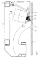
- Fig. 1 is a very schematic transverse section of the air chamber of a first embodiment of the device according to the invention.
- Fig. 2 is a perspective view of the element which is rotatable around the air chamber of Fig. 1.
- Fig. 3 is a very schematic section of the air chamber having nozzles according to a second embodiment of the device according to the invention.
- Fig. 4 is a section along the line IV-IV in Fig. 3.
- Fig. 5 is a schematic longitudinal section of a third example of an embodiment of the device according to the invention.
- Fig.s 6 and 7 are sections along the line VI-VI, VII-VII respectively in fig. 5.
- the present invention is intended for cleaning synthetic playing surfaces, such as for example tennis courts or hockey fields or the like, where a particulate material, such as sand or gravel is spread on a plastic fibre mat between the filaments. After some time this material sticks and sets causing the field to become hard and impervious to water and less good usable. In order to make the playing field better usable air is being ejected against the surface in small jets and with great force, causing the particular material to loosen, the material thereby being blowing upwards. If the particulate material is now being caught, it can be cleaned and a separation can for example be made between possibly re-usable coarse particles and finer dust and dirt particles, which particles are being collected and discharged. If thereupon clean, new or cleaned particulate material is spread on the playing surface, the playing surface is again good usable.
- a particulate material such as sand or gravel is spread on a plastic fibre mat between the filaments. After some time this material sticks and sets causing the field to become hard and impervious to
- the device is provided with a frame of a self riding vehicle or a towed vehicle, which frame is provided with a chassis.
- This vehicle is provided with an air compressor or is connected to an air compressor through a long hose of for example 120 meters for supplying compressed air of for instance approximately 10 bar.
- This compressed air is supplied to the inlet of an air block, which is shown in Fig. 1, and which is embodied as an air chamber 1 mounted substantially horizontally and more or less transverse to the direction of movement of the vehicle.
- the air chamber 1 has a circular cross section and is in this case provided with a slit-like air exhaust 2 pointed downwards and preferably at an angle of approximately 15 degrees relative to the vertical.
- the air chamber 1 can have a length of for example 100 cm and can be of a diameter of approximately 2 inch.
- One or more air chambers can operate next to each other in order to improve the working width.
- a rotatably drivable element which is provided with plurality of nozzles 4, acting as air passage means spaced along both the length and the circumference of the air chamber 1, or as the case may be extended along the rotating element 3, for example in one or more rows along a helical line across the wall of the rotatable element 3 (see Fig 2.).
- Fig. 1 it is further shown that, as seen in the direction of movement of the vehicle (right in Fig. 1), an inclined catching surface 5 is placed behind the air chamber, which catching surface catches the particulate material being ejected therein, and which further discharges it, for example through a flexible conveyer belt or shutter conveyer bringing the material through the unit to a point of discharge. From there on a further transport can take place through a vacuum hose or a motorized car.
- Fig.s 3 and 4 show a second example of an embodiment of the device according to the invention, whereby the housing 16 of the air block is provided with an air chamber 11, air exhausts 12, a rotatable element 13 and nozzles 14.
- the rotatable element 13 is not journalled concentrically around the air chamber 11, but next to it in a bearing chamber of the housing 16.
- the rotatable element 13 is constructed as a roller and is rotatable around an axis parallel to the air chamber 11.
- the nozzles 14 are provided stationary in the housing 16 of the air block and are in line with the air exhausts 12 of the air chamber radially relative to the rotatable element 13.
- This rotatable element 13 is provided with air passage channels 17, whereby adjacent air passage channels are turned through an angle around the axis of rotation, such that along the circumference of the rotatable element 13 the channels 17 show a helical line path. In two 180 degrees shifted rotational positions every channel comes in line with the air exhausts 12 of the air chamber 11 and the nozzles 14, causing air in those positions to be ejected through the nozzles. Because adjacent air passage channels 17 are angularly offset, air is ejected sequentially and it is also possible here to cover the whole surface to be cleaned without excessive air consumption. In each winding of the helical line of the channels 17 two nozzles 14 can be active simultaneously. A number of the housings 16 as shown can be coupled to each other, whereby the rotation of the rotatable elements 13 can be transferred through coupling means 18, 19.
- the Figs. 5-7 show a third variant of the invention, whereby the air block for alternatingly opening and closing of a row of nozzles 24 is provided with or is formed as a valve block 30.
- Recognizable are now an air chamber or air supply channel 21, nozzles 24 and a catch surface 25.
- the valve block which is positioned at an angle of 15 degrees has a number, in this case 12, of valves 31, shifting valves or other kinds of shutters which are included in channels 24' of the nozzles 24.
- each two channels 24' are connected to a valve 31 in order to reduce the number of valves 31.
- a nozzle 24 In a row of 6 adjacent nozzles each time a nozzle 24 is being opened sequentially, while the other five are closed. The position of the ejection of air then moves itself through this row.
- all kinds of arrangements of valves, channels and nozzles are possible.
- the invention provides a device and method, with the aid whereof air can be ejected every time on different closely spaced positions transverse to the direction of movement, thereby obtaining a good and reliable cleaning effect.
- the operating means for this selectively ejecting air or a similar medium thereby act as valves of shutters which, like in the first two embodiments, can be constructed both as rotatable elements for a large number of ejection openings, and be constructed as real valves, shutters or the like.
Landscapes
- Engineering & Computer Science (AREA)
- Architecture (AREA)
- Civil Engineering (AREA)
- Structural Engineering (AREA)
- Cleaning In General (AREA)
- Processes For Solid Components From Exhaust (AREA)
Claims (9)
- Dispositif destiné à traiter des surfaces de jeu synthétiques présentant, répandu sur elles, un matériau particulaire, du sable par exemple, comportant un châssis, lequel châssis est mobile selon une direction de propulsion, une centrale à air raccordée au châssis de façon sensiblement transversale à la direction de propulsion, la centrale à air ayant une entrée destinée à des moyens d'évacuation d'air comprimé et d'air orienté vers le bas (2 ; 12) longitudinalement espacés sur la longueur de la centrale à air, les moyens d'évacuation d'air pour éjecter de l'air étant conçus pour être déplacés au cours de leur mise en oeuvre selon la direction longitudinale de la centrale à air et, par conséquent, transversalement à la direction de propulsion grâce aux moyens opératoires (3, 4 ; 13, 14, 17 ; 24, 30, 31), la centrale à air étant sensiblement fixe par rapport aux moyens opératoires, caractérisé en ce que les moyens opératoires (3, 4 ; 13, 14, 17 ; 24, 30, 31) sont équipés de moyens à passages (4 ; 14, 17 ; 24, 31) destinés à, de façon alternée, ouvrir et fermer, selon la direction transversale, différentes parties des moyens d'évacuation d'air (2 ; 12) de telle sorte que l'air soit éjecté chaque fois en d'autres emplacements, transversalement à la direction de propulsion de la centrale à air.
- Dispositif selon la revendication 1, dans lequel les moyens à passages (4 ; 14, 17 ; 24, 31) comportent un grand nombre de buses (4 ; 14, 24) espacées sur la longueur de la centrale à air, seule une partie, en alternance, des buses étant alimentées en air comprimé.
- Dispositif selon la revendication 1 ou 2, dans lequel les moyens opératoires (3, 4 ; 13, 14, 17 ; 24, 30, 31) sont construits comme des obturateurs et, éventuellement, comme des vannes (31), aptes, de façon alternée, à ouvrir et fermer les canaux (24') des buses associées (24).
- Dispositif selon la revendication 1, 2 ou 3, dans lequel la centrale à air est construite comme une chambre à air (1 ; 11), les moyens opératoires étant, de leur côté, construits comme un élément mobile, en particulier un élément tournant (3 ; 13) apte à être mis en rotation autour d'un axe transversal à la direction de propulsion, lequel élément est équipé de moyens à passages (4 ; 17) destinés à, de façon alternée, ouvrir et fermer, selon la direction transversale, différentes parties des moyens d'évacuation d'air (2 ; 12), transversalement à la direction de propulsion.
- Dispositif selon la revendication 4, dans lequel les dits moyens à passages (4 ; 17) sont espacés le long de la circonférence et sur la longueur de l'élément tournant (3 ; 13), lesquels moyens à passages peuvent s'aligner avec des parties axiales séparées des moyens d'évacuation d'air (2 ; 12) et, éventuellement, déboucher à l'air libre au travers de buses fixes (14).
- Dispositif selon la revendication 5, dans lequel les dits moyens à passages (4 ; 17) sont divisés en une ou plusieurs formes en spirale autour de l'élément tournant (3 ; 13).
- Dispositif selon la revendication 6, dans lequel l'élément tournant (13) est constitué d'un rouleau, lequel rouleau est ajusté de façon serrée dans une boíte à roulements d'un logement (16), laquelle boíte à roulements est raccordée à la chambre à air (11), tandis que les moyens à passages (17) comprennent des canaux, lesquels canaux sont diposés de façon sensiblement radiale dans le rouleau, de sorte que les canaux adjacents sont angulairement mis en rotation autour de l'axe de rotation, et de sorte que les moyens d'évacuation d'air (12) et les buses (14) qui sont alignées avec ceux-ci sont disposés dans la paroi du logement (16).
- Procédé de traitement de surfaces de jeu synthétiques présentant, répandu sur elles, un matériau particulaire, du sable par exemple, de sorte que, grâce à des moyens d'évacuation d'air, de l'air comprimé est éjecté sur les surfaces de jeu à partir d'une centrale à air et sous un angle désiré, dans lequel le matériau particulaire est éjecté et est piégé, l'air étant éjecté au cours de la propulsion de la centrale à air transversalement à la direction de propulsion, et dans lequel la centrale à air est maintenue sensiblement fixe par rapport aux moyens opératoires tandis que grâce aux moyens opératoires l'air est éjecté, caractérisé en ce que l'air est éjecté chaque fois en d'autres emplacements, transversalement à la direction de propulsion de la centrale à air en ouvrant et en fermant, de façon alternée, des parties des moyens d'évacuation d'air.
- Procédé selon la revendication 8, de sorte qu'en tant que centrale à air une chambre à air est sélectionnée et de sorte qu'un élément, tournant de façon sensiblement continue par rapport la chambre à air, permet à l'air d'être éjecté au travers de moyens à passages d'air circonférenciellement et longitudinalement espacés chaque fois en différents emplacements, transversalement à la direction de propulsion de la chambre à air.
Applications Claiming Priority (2)
| Application Number | Priority Date | Filing Date | Title |
|---|---|---|---|
| NL1003404 | 1996-06-24 | ||
| NL1003404 | 1996-06-24 |
Publications (3)
| Publication Number | Publication Date |
|---|---|
| EP0816569A2 EP0816569A2 (fr) | 1998-01-07 |
| EP0816569A3 EP0816569A3 (fr) | 1998-05-13 |
| EP0816569B1 true EP0816569B1 (fr) | 2000-09-06 |
Family
ID=19763059
Family Applications (1)
| Application Number | Title | Priority Date | Filing Date |
|---|---|---|---|
| EP19970201927 Expired - Lifetime EP0816569B1 (fr) | 1996-06-24 | 1997-06-24 | Procédé et dispositif de traitement de surfaces de jeu synthétiques ayant des matériaux particulaires répandus |
Country Status (2)
| Country | Link |
|---|---|
| EP (1) | EP0816569B1 (fr) |
| DE (1) | DE69703010T2 (fr) |
Families Citing this family (9)
| Publication number | Priority date | Publication date | Assignee | Title |
|---|---|---|---|---|
| GB0212560D0 (en) * | 2002-05-31 | 2002-07-10 | Jayes Harold | Fluid pressure jetting |
| CN102605733B (zh) * | 2011-12-20 | 2014-04-16 | 中联重科股份有限公司 | 清扫工作头、清扫装置和道路清扫车 |
| US8454761B1 (en) * | 2011-12-21 | 2013-06-04 | Fermin Esson | Apparatus and system for cleaning baseball bases |
| CN103759914B (zh) * | 2014-01-24 | 2017-07-28 | 北京师范大学 | 一种全方位分层地表沙尘收集器 |
| CN105332355A (zh) * | 2015-11-23 | 2016-02-17 | 中联重科股份有限公司 | 滚扫装置及具有其的清洁车 |
| CN107440623B (zh) * | 2017-09-21 | 2020-09-15 | 芜湖乐佳自动化机械有限公司 | 除毛发扫地机 |
| CN107468165B (zh) * | 2017-09-21 | 2020-09-18 | 深圳市锦凌电子有限公司 | 抽吸刷扫地机器人 |
| CN108691292B (zh) * | 2018-06-06 | 2020-01-07 | 江苏阜光工程新技术有限公司 | 一种市政道路路面处理车 |
| CN108729390B (zh) * | 2018-06-06 | 2019-12-24 | 浙江勤泽美业环境科技有限公司 | 一种市政环卫清扫设备 |
Family Cites Families (4)
| Publication number | Priority date | Publication date | Assignee | Title |
|---|---|---|---|---|
| US4207650A (en) * | 1977-04-11 | 1980-06-17 | Crise W Paul | Cleaner using high velocity air jets having a double valve having an equal number of jet nozzles operating at all times |
| US4594749A (en) * | 1984-11-13 | 1986-06-17 | Waterman Dale G | Vacuum cleaner with air jet assist |
| AT387139B (de) * | 1985-11-21 | 1988-12-12 | Fink Karlo Branimir | Verfahrbares bodenreinigungsgeraet |
| AU647607B2 (en) * | 1991-05-20 | 1994-03-24 | Air Force Limited | Device for cleaning particulate material |
-
1997
- 1997-06-24 EP EP19970201927 patent/EP0816569B1/fr not_active Expired - Lifetime
- 1997-06-24 DE DE1997603010 patent/DE69703010T2/de not_active Expired - Lifetime
Also Published As
| Publication number | Publication date |
|---|---|
| EP0816569A2 (fr) | 1998-01-07 |
| DE69703010T2 (de) | 2001-05-10 |
| EP0816569A3 (fr) | 1998-05-13 |
| DE69703010D1 (de) | 2000-10-12 |
Similar Documents
| Publication | Publication Date | Title |
|---|---|---|
| US6364959B1 (en) | Process for cleaning a transport belt | |
| US5902414A (en) | Apparatus and method for renovating playing surfaces | |
| EP0816569A2 (fr) | Procédé et dispositif de traitement de surfaces de jeu synthétiques ayant des matériaux particulaires répandus | |
| PL173855B1 (pl) | Urządzenie do oczyszczania przedmiotów w ruchu | |
| US20090113856A1 (en) | High Efficiency Dust Separation System For Mobile Sweeper Vehicles | |
| US5979473A (en) | Method and apparatus for washing fruit | |
| WO2002089650A1 (fr) | Dispositif de nettoyage de surface a recirculation d'air | |
| JPH0722741B2 (ja) | パイプのクリーニング装置 | |
| US4693041A (en) | Surface blasting apparatus | |
| US4939808A (en) | Carpet cleaning apparatus | |
| WO2005118959A1 (fr) | Appareil pour le nettoyage du gazon synthetique | |
| JP3947893B2 (ja) | 乾式電気集塵機の洗浄装置 | |
| US7053335B2 (en) | Method and device for cleaning welding torches | |
| US5394586A (en) | Ballast sweeper dust control | |
| US6578714B2 (en) | Mobile washer with fluid reclamation system | |
| JPH0618800Y2 (ja) | 高圧流体加工装置 | |
| US7877838B2 (en) | Cleaning apparatus, such as for synthetic grass | |
| US7669283B2 (en) | Method and apparatus for deep cleaning rug or carpet | |
| CA2155913A1 (fr) | Collecteur de poussiere avec elements filtrants autonettoyants, a deux etages | |
| US20170009414A1 (en) | Improved Apparatus for Cleaning Synthetic Grass | |
| WO1993013845A1 (fr) | Procede et appareil pour nettoyer la toile de filtres a sacs | |
| WO2010060156A1 (fr) | Appareil de nettoyage | |
| JP2001161336A (ja) | 根菜用洗浄装置 | |
| JP4087988B2 (ja) | エアフィルタ用エレメントの清掃装置 | |
| NL1004055C2 (nl) | Werkwijze en inrichting voor het behandelen van synthetische speeloppervlakken met korrelvormig instrooimateriaal daarop. |
Legal Events
| Date | Code | Title | Description |
|---|---|---|---|
| PUAI | Public reference made under article 153(3) epc to a published international application that has entered the european phase |
Free format text: ORIGINAL CODE: 0009012 |
|
| AK | Designated contracting states |
Kind code of ref document: A2 Designated state(s): BE CH DE ES FR GB IT LI NL |
|
| PUAL | Search report despatched |
Free format text: ORIGINAL CODE: 0009013 |
|
| AK | Designated contracting states |
Kind code of ref document: A3 Designated state(s): AT BE CH DE DK ES FI FR GB GR IE IT LU MC NL PT SE |
|
| 17P | Request for examination filed |
Effective date: 19981027 |
|
| AKX | Designation fees paid |
Free format text: BE DE FI FR GB NL |
|
| RBV | Designated contracting states (corrected) |
Designated state(s): BE DE FI FR GB NL |
|
| RBV | Designated contracting states (corrected) |
Designated state(s): BE CH DE ES FR GB IT LI NL |
|
| GRAG | Despatch of communication of intention to grant |
Free format text: ORIGINAL CODE: EPIDOS AGRA |
|
| GRAG | Despatch of communication of intention to grant |
Free format text: ORIGINAL CODE: EPIDOS AGRA |
|
| GRAH | Despatch of communication of intention to grant a patent |
Free format text: ORIGINAL CODE: EPIDOS IGRA |
|
| 17Q | First examination report despatched |
Effective date: 19991229 |
|
| GRAH | Despatch of communication of intention to grant a patent |
Free format text: ORIGINAL CODE: EPIDOS IGRA |
|
| GRAA | (expected) grant |
Free format text: ORIGINAL CODE: 0009210 |
|
| AK | Designated contracting states |
Kind code of ref document: B1 Designated state(s): BE CH DE ES FR GB IT LI NL |
|
| PG25 | Lapsed in a contracting state [announced via postgrant information from national office to epo] |
Ref country code: LI Free format text: LAPSE BECAUSE OF FAILURE TO SUBMIT A TRANSLATION OF THE DESCRIPTION OR TO PAY THE FEE WITHIN THE PRESCRIBED TIME-LIMIT Effective date: 20000906 Ref country code: IT Free format text: LAPSE BECAUSE OF FAILURE TO SUBMIT A TRANSLATION OF THE DESCRIPTION OR TO PAY THE FEE WITHIN THE PRESCRIBED TIME-LIMIT;WARNING: LAPSES OF ITALIAN PATENTS WITH EFFECTIVE DATE BEFORE 2007 MAY HAVE OCCURRED AT ANY TIME BEFORE 2007. THE CORRECT EFFECTIVE DATE MAY BE DIFFERENT FROM THE ONE RECORDED. Effective date: 20000906 Ref country code: ES Free format text: THE PATENT HAS BEEN ANNULLED BY A DECISION OF A NATIONAL AUTHORITY Effective date: 20000906 Ref country code: CH Free format text: LAPSE BECAUSE OF FAILURE TO SUBMIT A TRANSLATION OF THE DESCRIPTION OR TO PAY THE FEE WITHIN THE PRESCRIBED TIME-LIMIT Effective date: 20000906 |
|
| REG | Reference to a national code |
Ref country code: CH Ref legal event code: EP |
|
| REF | Corresponds to: |
Ref document number: 69703010 Country of ref document: DE Date of ref document: 20001012 |
|
| ET | Fr: translation filed | ||
| REG | Reference to a national code |
Ref country code: CH Ref legal event code: PL |
|
| PLBE | No opposition filed within time limit |
Free format text: ORIGINAL CODE: 0009261 |
|
| STAA | Information on the status of an ep patent application or granted ep patent |
Free format text: STATUS: NO OPPOSITION FILED WITHIN TIME LIMIT |
|
| 26N | No opposition filed | ||
| REG | Reference to a national code |
Ref country code: GB Ref legal event code: IF02 |
|
| NLS | Nl: assignments of ep-patents |
Owner name: BASTIAAN WOUTER DOORNEWAARD H.O.D.N. SILICA NOVA Effective date: 20090331 |
|
| REG | Reference to a national code |
Ref country code: GB Ref legal event code: 732E Free format text: REGISTERED BETWEEN 20090625 AND 20090701 |
|
| REG | Reference to a national code |
Ref country code: FR Ref legal event code: TP |
|
| REG | Reference to a national code |
Ref country code: GB Ref legal event code: 732E Free format text: REGISTERED BETWEEN 20100204 AND 20100211 |
|
| REG | Reference to a national code |
Ref country code: FR Ref legal event code: PLFP Year of fee payment: 19 |
|
| PGFP | Annual fee paid to national office [announced via postgrant information from national office to epo] |
Ref country code: DE Payment date: 20150624 Year of fee payment: 19 |
|
| PGFP | Annual fee paid to national office [announced via postgrant information from national office to epo] |
Ref country code: FR Payment date: 20150619 Year of fee payment: 19 |
|
| PGFP | Annual fee paid to national office [announced via postgrant information from national office to epo] |
Ref country code: NL Payment date: 20150629 Year of fee payment: 19 |
|
| PGFP | Annual fee paid to national office [announced via postgrant information from national office to epo] |
Ref country code: BE Payment date: 20150630 Year of fee payment: 19 |
|
| PGFP | Annual fee paid to national office [announced via postgrant information from national office to epo] |
Ref country code: GB Payment date: 20160624 Year of fee payment: 20 |
|
| PG25 | Lapsed in a contracting state [announced via postgrant information from national office to epo] |
Ref country code: BE Free format text: LAPSE BECAUSE OF NON-PAYMENT OF DUE FEES Effective date: 20160630 |
|
| REG | Reference to a national code |
Ref country code: DE Ref legal event code: R119 Ref document number: 69703010 Country of ref document: DE |
|
| REG | Reference to a national code |
Ref country code: NL Ref legal event code: MM Effective date: 20160701 |
|
| REG | Reference to a national code |
Ref country code: FR Ref legal event code: ST Effective date: 20170228 |
|
| PG25 | Lapsed in a contracting state [announced via postgrant information from national office to epo] |
Ref country code: DE Free format text: LAPSE BECAUSE OF NON-PAYMENT OF DUE FEES Effective date: 20170103 Ref country code: FR Free format text: LAPSE BECAUSE OF NON-PAYMENT OF DUE FEES Effective date: 20160630 |
|
| PG25 | Lapsed in a contracting state [announced via postgrant information from national office to epo] |
Ref country code: NL Free format text: LAPSE BECAUSE OF NON-PAYMENT OF DUE FEES Effective date: 20160701 |
|
| REG | Reference to a national code |
Ref country code: GB Ref legal event code: PE20 Expiry date: 20170623 |
|
| PG25 | Lapsed in a contracting state [announced via postgrant information from national office to epo] |
Ref country code: GB Free format text: LAPSE BECAUSE OF EXPIRATION OF PROTECTION Effective date: 20170623 |