EP0816590A2 - Elément de montage avec support, pour fixer des panneaux de vêture sur ce support - Google Patents
Elément de montage avec support, pour fixer des panneaux de vêture sur ce support Download PDFInfo
- Publication number
- EP0816590A2 EP0816590A2 EP97110445A EP97110445A EP0816590A2 EP 0816590 A2 EP0816590 A2 EP 0816590A2 EP 97110445 A EP97110445 A EP 97110445A EP 97110445 A EP97110445 A EP 97110445A EP 0816590 A2 EP0816590 A2 EP 0816590A2
- Authority
- EP
- European Patent Office
- Prior art keywords
- carrier
- tabs
- fastening element
- metal strip
- fastener
- Prior art date
- Legal status (The legal status is an assumption and is not a legal conclusion. Google has not performed a legal analysis and makes no representation as to the accuracy of the status listed.)
- Withdrawn
Links
Images


Classifications
-
- E—FIXED CONSTRUCTIONS
- E04—BUILDING
- E04F—FINISHING WORK ON BUILDINGS, e.g. STAIRS, FLOORS
- E04F13/00—Coverings or linings, e.g. for walls or ceilings
- E04F13/07—Coverings or linings, e.g. for walls or ceilings composed of covering or lining elements; Sub-structures therefor; Fastening means therefor
- E04F13/08—Coverings or linings, e.g. for walls or ceilings composed of covering or lining elements; Sub-structures therefor; Fastening means therefor composed of a plurality of similar covering or lining elements
- E04F13/0801—Separate fastening elements
- E04F13/0803—Separate fastening elements with load-supporting elongated furring elements between wall and covering elements
- E04F13/081—Separate fastening elements with load-supporting elongated furring elements between wall and covering elements with additional fastening elements between furring elements and covering elements
- E04F13/0821—Separate fastening elements with load-supporting elongated furring elements between wall and covering elements with additional fastening elements between furring elements and covering elements the additional fastening elements located in-between two adjacent covering elements
- E04F13/0823—Separate fastening elements with load-supporting elongated furring elements between wall and covering elements with additional fastening elements between furring elements and covering elements the additional fastening elements located in-between two adjacent covering elements piercing the side faces of the covering elements
-
- F—MECHANICAL ENGINEERING; LIGHTING; HEATING; WEAPONS; BLASTING
- F16—ENGINEERING ELEMENTS AND UNITS; GENERAL MEASURES FOR PRODUCING AND MAINTAINING EFFECTIVE FUNCTIONING OF MACHINES OR INSTALLATIONS; THERMAL INSULATION IN GENERAL
- F16B—DEVICES FOR FASTENING OR SECURING CONSTRUCTIONAL ELEMENTS OR MACHINE PARTS TOGETHER, e.g. NAILS, BOLTS, CIRCLIPS, CLAMPS, CLIPS OR WEDGES; JOINTS OR JOINTING
- F16B15/00—Nails; Staples
- F16B15/0023—Nail plates
- F16B15/003—Nail plates with teeth cut out from the material of the plate
- F16B15/0038—Nail plates with teeth cut out from the material of the plate only on the perimeter of the plate
Definitions
- the invention relates to a fastener with carrier, for holding cladding panels this carrier, the fastener from a
- a metal strip in its original position is flat and has several tabs that protrude from the plane of the metal strip are bendable, a first Group of tabs is at least partially intended To enclose parts of the carrier like a clamp for fastening the fastener on the carrier; and a second Group of tabs is designed to have at least one cladding panel to encompass between one Part of the carrier and the tab of the second group, to attach the cladding panel to the beam and Fastener.
- DE-GM 89 02 318 is a sanitary element (Carrier, frame, frame) known, both on the ground as well as with its back against a wall and both vertical and horizontal Spars includes. Be on such a sanitary element Cladding panels attached, on which then plastering is applied or tiles (tiles) are laid on it will. So far, the cladding panels have been Screws on the vertical and horizontal bars of the Screwed to the frame. It takes a lot of work, a lot Screws and is therefore expensive.
- plastically deformable metal strips which are clamped on the carrier on the one hand, and on the other reach behind the cladding panels.
- Such Bracket of the cladding panels on the beam goes quickly and without special tools and without screws; so there is no need for a drill.
- this fastener can only be found in Fasten cladding panels lying on one level.
- the invention seeks to remedy this.
- the Invention as characterized in the claims solves the task including a fastener a bracket for attaching cladding panels to create this carrier, in which from the second Group of tabs opposite end of the fastener sawtooth, bendable tips available are the claws that are meant to in a form-fitting manner in an adjacent cladding panel intervene.
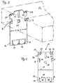
- Figures 1 to 4 are the components that correspond to those in Swiss Patent Application No. 1776 / 94-2, provided with the same reference numbers.
- the carrier mentioned is a vertical one in FIG Spar 1 and a horizontal spar 2 are shown are connected to each other by means of a screw 3.
- Fig. 2 shows a vertical cladding panel 4 and a horizontal one Cladding panel 20 using fasteners are attached to the carrier, with only one fastener 21 is visible.
- This fastener 21 is shown in Fig. 1 in its initial position and is in Figs. 2, 3 and 4 in two different Functional positions.
- the carrier can e.g. a composed of spars with different profiles Be rack. 2, both the vertical spar 1 as well as the horizontal spar 2 an L-profile.
- the horizontal one Spar 2 has two legs 6 and 7.
- the fastener 21 shown in FIG. 1 consists of a metal strip, which in its in Fig. 1st shown starting position is flat and several tabs 8th to 13. These tabs are cut out 14 and 15 formed.
- the metal strip 21 has an elongated Shape and is provided with at least one slot 16, that extends in the longitudinal direction of the metal strip.
- the metal strip still has perforations 17 and 18, which indicate bending lines.
- the tabs 8, 9, 10 and 11 form a first Group
- the tabs 12 and 13 form a second Group.
- the first group of tabs serves to help with the use of the fastening element 21 according to FIG. 2 and the right side of FIG. 4, the fastening element 21 (Metal strip) to attach to spar 2, and the tabs 12 and 13 of the second group serve to plate 4 to attach to the spar 2.
- the tabs 8 to 13 from the plane of the metal strip shown in FIG. 1 are bent, and the metal strip according to Fig. 1 is bent at right angles to the bending line 17. 4 the spar 2 has been omitted on the right-hand side; you can only see the fastener 21 and the two Cladding panels 4 and 20.
- the fastener 21 shown in FIG. 1 has the four tabs 8, 9, 10 and 11 of the first group and the two tabs 12 and 13 of the second group.
- the Tab 13 is for the horizontal shown in FIG. 2 Plate 10 is determined, and the tab 12 is for the vertical Plate 4 determined.
- the tabs 8 to 11 are intended to be the two To include legs 6 and 7 of the spar 2 like a clamp for fastening the fastening element 21 to the spar 2.
- the tab 12 is intended to enclose (reach behind) the plate 4, that the plate 4 between the leg 6 of the Holmes 2 and the tab 12 is for attaching the plate 4 on the carrier 1,2.
- the tab 13 is intended to the horizontal To enclose plate 20 (reach behind) so that the plate 20 between a second carrier 22 and the tab 13 lies, for fastening the plate 20 both on the carrier 1, 2nd as well as on the carrier 22.
- the tabs 8 to 11 of the first group are narrower than the tabs 12, 13 of the second group.
- the Both tabs 12 and 13 can be at the corners of the free Provide tab end with claw-like bends 19 intended to be claw-like on the plates 4 and 20 to attack.
- claw-like bends 19 intended to be claw-like on the plates 4 and 20 to attack.
- the elongated hole 16 in the metal strip serves around the horizontal spar 2 with plate 4 compared to the vertical spar 1 to lower. This will now the fastener 21 with its slot 16 between the spars 1 and 2 fastened by means of the screw 3, so that the plate 4 with spar 2 and fastener 21 hang downwards from screw 3.
- the fastener 21 is not bent at the perforations 17, and the fastener is by means of a screw, not shown, which sits in a hole 25 of the metal strip on the carrier 22 attached. Then serve in this further use the tabs 8, 9 no longer the fastening element 2 to attach to the spar, but serve in one inclined position to the plane of the metal strip a support for the horizontal cladding panel 20 to form (see Fig. 3 and Fig. 4, left side).
Landscapes
- Engineering & Computer Science (AREA)
- Architecture (AREA)
- General Engineering & Computer Science (AREA)
- Civil Engineering (AREA)
- Structural Engineering (AREA)
- Mechanical Engineering (AREA)
- Roof Covering Using Slabs Or Stiff Sheets (AREA)
- Finishing Walls (AREA)
- Slide Fasteners, Snap Fasteners, And Hook Fasteners (AREA)
- Absorbent Articles And Supports Therefor (AREA)
- Orthopedics, Nursing, And Contraception (AREA)
Applications Claiming Priority (2)
| Application Number | Priority Date | Filing Date | Title |
|---|---|---|---|
| DE29611333U DE29611333U1 (de) | 1996-06-28 | 1996-06-28 | Befestigungselement mit Träger |
| DE29611333U | 1996-06-28 |
Publications (2)
| Publication Number | Publication Date |
|---|---|
| EP0816590A2 true EP0816590A2 (fr) | 1998-01-07 |
| EP0816590A3 EP0816590A3 (fr) | 1998-07-08 |
Family
ID=8025811
Family Applications (1)
| Application Number | Title | Priority Date | Filing Date |
|---|---|---|---|
| EP97110445A Withdrawn EP0816590A3 (fr) | 1996-06-28 | 1997-06-26 | Elément de montage avec support, pour fixer des panneaux de vêture sur ce support |
Country Status (2)
| Country | Link |
|---|---|
| EP (1) | EP0816590A3 (fr) |
| DE (1) | DE29611333U1 (fr) |
Cited By (2)
| Publication number | Priority date | Publication date | Assignee | Title |
|---|---|---|---|---|
| EP1308576A1 (fr) * | 2001-11-02 | 2003-05-07 | Jean-Edouard Gissinger | Pièce de fixation de panne, notamment pour réaliser des couvertures ou bardages doubles |
| RU204495U1 (ru) * | 2020-12-15 | 2021-05-27 | Общество с ограниченной ответственностью "Мультиплит" | Соединительный элемент |
Families Citing this family (2)
| Publication number | Priority date | Publication date | Assignee | Title |
|---|---|---|---|---|
| FR2797901B1 (fr) * | 1999-08-31 | 2001-10-26 | Knauf Snc | Procede et dispositif pour fixer des panneaux sur un support |
| DE202013100161U1 (de) | 2013-01-11 | 2013-02-25 | Knauf Gips Kg | Trockenbaudecke/-wand |
Family Cites Families (4)
| Publication number | Priority date | Publication date | Assignee | Title |
|---|---|---|---|---|
| US4395858A (en) * | 1981-07-06 | 1983-08-02 | Gwyther Donald W | Panel mounting system and method |
| DE3148880A1 (de) * | 1981-12-10 | 1983-06-23 | Kaefer Isoliertechnik Gmbh & Co Kg, 2800 Bremen | "vorrichtung zur befestigung der elemente eines schallabsorptionssystems in reflexionsarmen raeumen" |
| DE4105186C2 (de) * | 1991-02-20 | 2000-09-21 | Boegle Kg Wilhelm | Halteelemente für plattenförmige Bauelemente |
| DE4222654C2 (de) * | 1992-07-10 | 2001-11-22 | Boegle Kg Wilhelm | Halteelement für Wandverkleidungen, beispielsweise Abschlußleisten |
-
1996
- 1996-06-28 DE DE29611333U patent/DE29611333U1/de not_active Expired - Lifetime
-
1997
- 1997-06-26 EP EP97110445A patent/EP0816590A3/fr not_active Withdrawn
Cited By (3)
| Publication number | Priority date | Publication date | Assignee | Title |
|---|---|---|---|---|
| EP1308576A1 (fr) * | 2001-11-02 | 2003-05-07 | Jean-Edouard Gissinger | Pièce de fixation de panne, notamment pour réaliser des couvertures ou bardages doubles |
| FR2831903A1 (fr) * | 2001-11-02 | 2003-05-09 | Jean Edouard Gissinger | Piece de fixation de panne, notamment pour realiser des couvertures ou bardages doubles |
| RU204495U1 (ru) * | 2020-12-15 | 2021-05-27 | Общество с ограниченной ответственностью "Мультиплит" | Соединительный элемент |
Also Published As
| Publication number | Publication date |
|---|---|
| EP0816590A3 (fr) | 1998-07-08 |
| DE29611333U1 (de) | 1996-09-05 |
Similar Documents
| Publication | Publication Date | Title |
|---|---|---|
| EP2815191B1 (fr) | Dispositif de support pour au moins un module solaire | |
| DE3033114C2 (de) | Vorrichtung zur Bildung eines Kastenrahmens für Klimagerätekästen u.dgl. | |
| DE3248438A1 (de) | Halterung fuer gitterzaeune | |
| DE29611333U1 (de) | Befestigungselement mit Träger | |
| DE2510949A1 (de) | Trennwand zum einbau in gebaeude | |
| DE102017000924A1 (de) | Plattenhalter | |
| DE2352173B2 (de) | Zaunfeld | |
| CH688740A5 (de) | Befestigungselement mit Gestell, zum Befestigen von Verkleidungsplatten an diesem Gestell. | |
| EP0761904A1 (fr) | Système de montage pour panneaux | |
| DE7225523U (de) | Bausatz für Bandrasterprofilschienen mit Kreuzverbindungsstück | |
| DE9301520U1 (de) | Vorrichtung zur Befestigung von Installationselementen | |
| DE68911957T2 (de) | Bilderrahmen. | |
| DE102017114129A1 (de) | Montageplattenanordnung für den Innenausbau eines Schaltschranks und ein entsprechender Schaltschrank | |
| AT304025B (de) | Vorrichtung zur Aufhängung von Untersichtsplatten | |
| DE1784413C3 (de) | Trennwand | |
| AT406174B (de) | Befestigungsteil für profile | |
| DE1778378C (de) | Befestigungsanordnung fur Baueinheiten, insbesondere Turlautsprecher, auf der Ruck seite von Anreihfrontplatten aus Strangpro fil Material | |
| DE2049509A1 (de) | Halterung für Anschlußelementeträger | |
| DE1484071B1 (de) | Verfahren zur Befestigung eines plattenf¦rmigen K¦rpers aus glasigem Siliciumoxyd auf einem tragenden Unterbau | |
| DE2042888A1 (de) | Isolierwand | |
| AT217682B (de) | Verkleidung mit im allgemeinen aus Metall bestehenden Paneelen | |
| DE3152918A1 (de) | Abfangkonsole | |
| DE1259547B (de) | Aufhaengevorrichtung fuer Haengedecken aus Kassettenplatten | |
| DE202019105545U1 (de) | Modulares Leitsystem | |
| DE8900335U1 (de) | Wandtafel o.dgl. |
Legal Events
| Date | Code | Title | Description |
|---|---|---|---|
| PUAI | Public reference made under article 153(3) epc to a published international application that has entered the european phase |
Free format text: ORIGINAL CODE: 0009012 |
|
| AK | Designated contracting states |
Kind code of ref document: A2 Designated state(s): AT BE CH DE DK ES FI FR GB GR IE IT LI LU MC NL PT SE |
|
| AX | Request for extension of the european patent |
Free format text: AL;LT;LV;RO;SI |
|
| PUAL | Search report despatched |
Free format text: ORIGINAL CODE: 0009013 |
|
| AK | Designated contracting states |
Kind code of ref document: A3 Designated state(s): AT BE CH DE DK ES FI FR GB GR IE IT LI LU MC NL PT SE |
|
| AX | Request for extension of the european patent |
Free format text: AL;LT;LV;RO;SI |
|
| AKX | Designation fees paid | ||
| RBV | Designated contracting states (corrected) | ||
| STAA | Information on the status of an ep patent application or granted ep patent |
Free format text: STATUS: THE APPLICATION IS DEEMED TO BE WITHDRAWN |
|
| 18D | Application deemed to be withdrawn |
Effective date: 19990109 |
|
| REG | Reference to a national code |
Ref country code: DE Ref legal event code: 8566 |