EP0816602A2 - Selbstverriegelndes Einsteckschloss - Google Patents
Selbstverriegelndes Einsteckschloss Download PDFInfo
- Publication number
- EP0816602A2 EP0816602A2 EP97110217A EP97110217A EP0816602A2 EP 0816602 A2 EP0816602 A2 EP 0816602A2 EP 97110217 A EP97110217 A EP 97110217A EP 97110217 A EP97110217 A EP 97110217A EP 0816602 A2 EP0816602 A2 EP 0816602A2
- Authority
- EP
- European Patent Office
- Prior art keywords
- lock
- slide
- bolt
- self
- locking
- Prior art date
- Legal status (The legal status is an assumption and is not a legal conclusion. Google has not performed a legal analysis and makes no representation as to the accuracy of the status listed.)
- Granted
Links
Images

Classifications
-
- E—FIXED CONSTRUCTIONS
- E05—LOCKS; KEYS; WINDOW OR DOOR FITTINGS; SAFES
- E05B—LOCKS; ACCESSORIES THEREFOR; HANDCUFFS
- E05B63/00—Locks or fastenings with special structural characteristics
- E05B63/18—Locks or fastenings with special structural characteristics with arrangements independent of the locking mechanism for retaining the bolt or latch in the retracted position
- E05B63/20—Locks or fastenings with special structural characteristics with arrangements independent of the locking mechanism for retaining the bolt or latch in the retracted position released automatically when the wing is closed
-
- E—FIXED CONSTRUCTIONS
- E05—LOCKS; KEYS; WINDOW OR DOOR FITTINGS; SAFES
- E05B—LOCKS; ACCESSORIES THEREFOR; HANDCUFFS
- E05B55/00—Locks in which a sliding latch is used also as a locking bolt
-
- E—FIXED CONSTRUCTIONS
- E05—LOCKS; KEYS; WINDOW OR DOOR FITTINGS; SAFES
- E05B—LOCKS; ACCESSORIES THEREFOR; HANDCUFFS
- E05B59/00—Locks with latches separate from the lock-bolts or with a plurality of latches or lock-bolts
-
- E—FIXED CONSTRUCTIONS
- E05—LOCKS; KEYS; WINDOW OR DOOR FITTINGS; SAFES
- E05B—LOCKS; ACCESSORIES THEREFOR; HANDCUFFS
- E05B63/00—Locks or fastenings with special structural characteristics
- E05B63/0065—Operating modes; Transformable to different operating modes
-
- E—FIXED CONSTRUCTIONS
- E05—LOCKS; KEYS; WINDOW OR DOOR FITTINGS; SAFES
- E05B—LOCKS; ACCESSORIES THEREFOR; HANDCUFFS
- E05B15/00—Other details of locks; Parts for engagement by bolts of fastening devices
- E05B15/10—Bolts of locks or night latches
- E05B15/102—Bolts having movable elements
- E05B2015/105—Two pivoting latch elements with opposite inclined surfaces mounted on one slidable main latch-piece
-
- E—FIXED CONSTRUCTIONS
- E05—LOCKS; KEYS; WINDOW OR DOOR FITTINGS; SAFES
- E05B—LOCKS; ACCESSORIES THEREFOR; HANDCUFFS
- E05B63/00—Locks or fastenings with special structural characteristics
- E05B63/18—Locks or fastenings with special structural characteristics with arrangements independent of the locking mechanism for retaining the bolt or latch in the retracted position
- E05B63/20—Locks or fastenings with special structural characteristics with arrangements independent of the locking mechanism for retaining the bolt or latch in the retracted position released automatically when the wing is closed
- E05B2063/207—Automatic deadlocking
-
- E—FIXED CONSTRUCTIONS
- E05—LOCKS; KEYS; WINDOW OR DOOR FITTINGS; SAFES
- E05B—LOCKS; ACCESSORIES THEREFOR; HANDCUFFS
- E05B65/00—Locks or fastenings for special use
- E05B65/10—Locks or fastenings for special use for panic or emergency doors
- E05B65/1086—Locks with panic function, e.g. allowing opening from the inside without a ley even when locked from the outside
Definitions
- the invention relates to a self-locking mortise lock with an in Longitudinal direction of the lock by means of a key against a spring force slidable, a bolt controlling slide and a Slider with spring bolt locked when the bolt is closed Control unit, which when the door is closed while unlocking the slider releases the latch.
- the DE 43 37 969 A1 is a self-locking security door lock of the genus mentioned at the beginning.
- the known Door lock has one or more bolts that are shared by one Slider - referred to there as the gear element - are operated.
- the gear element itself is a by means of a lock bit Lock cylinder raised and over in its raised position Pushbuttons, which act on projections of the gear element, with the included Tie or included rules kept.
- the button or buttons give the gear element and so that the latch lock is free.
- the bar or bars can also by means of a door handle can be operated; a lock latch is in the known Lock not provided.
- the security door lock described above also has a panic function on.
- the invention solves the stated problem by the teaching according to claim 1.
- the invention takes advantage of the consideration that the slide usually by striking the key or lock cylinder bit on a switch cam of the slide in the longitudinal direction of the lock is moved.
- the assignment of a stop in the area of Lock cylinder contour now enables the key or lock cylinder bit with the help of the key in a certain end position or stop position to bring in the key or lock cylinder bit supports the slider so that it is prevented from moving that Closing the latch triggers. For this there is an immediate on the slide corresponding with the key or lock cylinder bit Switch cams arranged.
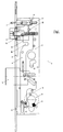
- a mortise lock with 1 is identical Lock plate with 2, a faceplate with 3, a slide with 4, a bolt with 5, a cross trap with 6 and a control part with 7.
- FIG. 1 there is a locking cylinder bit 8 in its lower starting position on the right in the image plane.
- the well known Way arranged and not shown in the drawing spring moved the slider 4 to its lower position.
- the latch 5 is thereby pre-closed;
- the cross latch 6 is by the on a pin 13th of the cross drop shaft abutting edge 12 of the slide 4th locked against inference.
- the control part 7 lies with its bolt extension 17 on the cross trap 6 and is thus in the in FIG. 1 position shown.
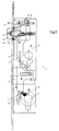
- the locking cylinder bit 8 is approximately at 160 ° have been moved in a clockwise direction, so that it over a Switching cam 11 on the slide 4, the slide 4 in that shown in Figure 2 Position. It has a hook-like extension 15 on Slider 4 drive over a retaining cam 14 on the spring-loaded control part 7, so that the slide 4 is now held by the control part 7.
- the bolt 5 has been pulled in. Since the slide 4 with is provided with a slot 16, the cross latch 6 can in this situation immerse the pin 13 in the slot 16 on the cross shaft, i.e. the Cross trap 6 is free and can be closed as desired, the Preliminary spring-loaded in a known manner.
- the cross latch 6 retracts and moves the control part 7 over the bolt extension 17 in the image plane to the right, so that the control part 7 releases the hook-like extension 15 of the slide 4; however, the slide 4 is still at one during the closing process Downward movement prevented because the pin 13 in the slot 16 of the Slider 4 immersed.
Landscapes
- Engineering & Computer Science (AREA)
- Structural Engineering (AREA)
- Closing And Opening Devices For Wings, And Checks For Wings (AREA)
- Lock And Its Accessories (AREA)
- Joining Of Building Structures In Genera (AREA)
- Control Of Presses (AREA)
- Clamps And Clips (AREA)
- Mutual Connection Of Rods And Tubes (AREA)
Abstract
Description
- Figur 1:
- das Einsteckschloß bei geschlossener Tür mit gesperrter Kreuzfalle und vorgeschlossenem Riegel
- Figur 2:
- das Einsteckschloß bei geöffneter Tür mit freier Kreuzfalle und eingezogenem Riegel
- Figur 3:
- das Einsteckschloß bei geöffneter oder geschlossener Tür mit freier Kreuzfalle, eingezogenem Riegel und gesperrtem Schieber

- 1
- Einsteckschloß
- 2
- Schloßblech
- 3
- Stulp
- 4
- Schieber
- 5
- Riegel
- 6
- Kreuzfalle
- 7
- Steuerteil
- 8
- Schlüssel- oder Schließzylinderbart
- 9
- Schließzylinderkontur
- 10
- Anschlag
- 11
- Schaltnocken
- 12
- Anschlagkante
- 13
- Zapfen
- 14
- Haltenocken
- 15
- hakenartiger Fortsatz
- 16
- Schlitz
- 17
- Riegelfortsatz
Claims (2)
- Selbstverriegelndes Einsteckschloß mit einem in Längsrichtung des Schlosses mittels eines Schlüssels gegen eine Federkraft verschieblichen, einen Riegel steuernden Schieber und einem den Schieber bei rückgeschlossenem Riegel arretierenden federbelasteten Steuerteil, welches beim Schließen der Tür unter Aufhebung der Arretierung des Schiebers den Riegelvorschluß freigibt, dadurch gekennzeichnet, daß das Einsteckschloß (1) eine bei vorgeschlossenem Riegel (5) vom Schieber (4) gesperrte und bei rückgeschlossenem Riegel (5) vom Schieber (4) freigegebene Kreuzfalle (6) aufweist und der Schieber (4) bei freigegebener Kreuzfalle (6) bei Anlage des Schlüssel- oder Schließzylinderbartes (8) an einem im Bereich einer Schließzylinderkontur (9) angeordneten Anschlag (10) gesperrt ist.
- Selbstverriegelndes Einsteckschloß nach Anspruch 1, dadurch gekennzeichnet, daß am Schieber (4) ein unmittelbar mit dem Schlüssel- oder Schließzylinderbart (8) korrespondierender Schaltnocken (11) angeordnet ist.
Applications Claiming Priority (2)
| Application Number | Priority Date | Filing Date | Title |
|---|---|---|---|
| DE19626752 | 1996-07-03 | ||
| DE19626752A DE19626752C2 (de) | 1996-07-03 | 1996-07-03 | Selbstverriegelndes Einsteckschloß |
Publications (3)
| Publication Number | Publication Date |
|---|---|
| EP0816602A2 true EP0816602A2 (de) | 1998-01-07 |
| EP0816602A3 EP0816602A3 (de) | 1998-01-14 |
| EP0816602B1 EP0816602B1 (de) | 1999-08-25 |
Family
ID=7798796
Family Applications (1)
| Application Number | Title | Priority Date | Filing Date |
|---|---|---|---|
| EP97110217A Expired - Lifetime EP0816602B1 (de) | 1996-07-03 | 1997-06-23 | Selbstverriegelndes Einsteckschloss |
Country Status (3)
| Country | Link |
|---|---|
| EP (1) | EP0816602B1 (de) |
| AT (1) | ATE183802T1 (de) |
| DE (2) | DE19626752C2 (de) |
Cited By (10)
| Publication number | Priority date | Publication date | Assignee | Title |
|---|---|---|---|---|
| WO1999067489A1 (de) * | 1998-06-22 | 1999-12-29 | Dorma Gmbh + Co. Kg | Selbstverriegelndes panikschloss |
| EP1031687A1 (de) * | 1999-02-17 | 2000-08-30 | ABUS August Bremicker Söhne KG | Fensterschloss |
| DE10206512A1 (de) * | 2002-02-16 | 2003-09-04 | Schlechtendahl & Soehne Wilh | Selbstverriegelndes Panikschloß |
| RU2334857C2 (ru) * | 2003-05-14 | 2008-09-27 | Аблой Ой | Устройство для придания направления при блокировании фиксируемой защелки в дверном замке |
| WO2009060483A1 (en) * | 2007-11-07 | 2009-05-14 | Assa Abloy Italia S.P.A. | Lock |
| EP2151536A3 (de) * | 2008-08-06 | 2010-09-08 | ISEO SERRATURE S.p.A. | Schloss mit mehreren automatischen Schließpunkten |
| EP2754795A3 (de) * | 2013-01-11 | 2015-07-29 | Wilh. Schlechtendahl & Söhne GmbH & Co. KG | Gegenkasten oder Einsteckschloss |
| EP3243985A1 (de) * | 2016-05-09 | 2017-11-15 | GEZE GmbH | Schloss für einen schwenkbaren flügel |
| FR3099196A1 (fr) * | 2019-07-23 | 2021-01-29 | Ferco | Ferrure de verrouillage à moyens de rappel élastique en position verrouillée. |
| GR1010491B (el) * | 2022-09-03 | 2023-06-16 | Κωνσταντινος Ιωαννη Πελεκας | Κλειδαρια εμποριου τυπου 'γλωσσου' που κλειδωνει αυτοματα σε καθε κλεισιμο της θυρας |
Families Citing this family (7)
| Publication number | Priority date | Publication date | Assignee | Title |
|---|---|---|---|---|
| DE19905596C2 (de) * | 1999-02-11 | 2003-11-27 | Wilka Schliestechnik Gmbh | Selbstverriegelndes Einsteckschloß |
| DE19951866C2 (de) * | 1999-10-27 | 2001-09-20 | Dorma Gmbh & Co Kg | Anti-Panik-Türschloß |
| DE10162694B4 (de) * | 2001-12-19 | 2004-07-29 | Geze Gmbh | Türöffner nach dem Ruhestromprinzip |
| DE10261129B4 (de) * | 2002-12-20 | 2005-01-13 | Geze Gmbh | Selbstverriegelndes Schloss |
| DE202007017644U1 (de) * | 2007-12-18 | 2009-04-30 | Mayer & Co. | Schloss |
| DE202011103191U1 (de) | 2011-07-06 | 2012-10-11 | Kfv Karl Fliether Gmbh & Co. Kg | Selbstverriegelndes Schloss |
| DE102014104129A1 (de) * | 2014-03-25 | 2015-10-01 | Assa Abloy Nederland B.V. | Schloss für Tür oder Fenster |
Family Cites Families (2)
| Publication number | Priority date | Publication date | Assignee | Title |
|---|---|---|---|---|
| DE4337969A1 (de) * | 1993-10-15 | 1995-04-20 | Theodor Krachten | Selbstverriegelndes Sicherheitstürschloß |
| EP0668425B1 (de) * | 1994-02-21 | 1998-04-08 | Hellmüller + Zingg AG | Türschloss |
-
1996
- 1996-07-03 DE DE19626752A patent/DE19626752C2/de not_active Expired - Fee Related
-
1997
- 1997-06-23 DE DE59700363T patent/DE59700363D1/de not_active Expired - Fee Related
- 1997-06-23 EP EP97110217A patent/EP0816602B1/de not_active Expired - Lifetime
- 1997-06-23 AT AT97110217T patent/ATE183802T1/de not_active IP Right Cessation
Cited By (11)
| Publication number | Priority date | Publication date | Assignee | Title |
|---|---|---|---|---|
| WO1999067489A1 (de) * | 1998-06-22 | 1999-12-29 | Dorma Gmbh + Co. Kg | Selbstverriegelndes panikschloss |
| EP1031687A1 (de) * | 1999-02-17 | 2000-08-30 | ABUS August Bremicker Söhne KG | Fensterschloss |
| DE10206512A1 (de) * | 2002-02-16 | 2003-09-04 | Schlechtendahl & Soehne Wilh | Selbstverriegelndes Panikschloß |
| DE10206512B4 (de) * | 2002-02-16 | 2005-10-06 | Wilh. Schlechtendahl & Söhne GmbH & Co KG | Selbstverriegelndes Panikschloß |
| RU2334857C2 (ru) * | 2003-05-14 | 2008-09-27 | Аблой Ой | Устройство для придания направления при блокировании фиксируемой защелки в дверном замке |
| WO2009060483A1 (en) * | 2007-11-07 | 2009-05-14 | Assa Abloy Italia S.P.A. | Lock |
| EP2151536A3 (de) * | 2008-08-06 | 2010-09-08 | ISEO SERRATURE S.p.A. | Schloss mit mehreren automatischen Schließpunkten |
| EP2754795A3 (de) * | 2013-01-11 | 2015-07-29 | Wilh. Schlechtendahl & Söhne GmbH & Co. KG | Gegenkasten oder Einsteckschloss |
| EP3243985A1 (de) * | 2016-05-09 | 2017-11-15 | GEZE GmbH | Schloss für einen schwenkbaren flügel |
| FR3099196A1 (fr) * | 2019-07-23 | 2021-01-29 | Ferco | Ferrure de verrouillage à moyens de rappel élastique en position verrouillée. |
| GR1010491B (el) * | 2022-09-03 | 2023-06-16 | Κωνσταντινος Ιωαννη Πελεκας | Κλειδαρια εμποριου τυπου 'γλωσσου' που κλειδωνει αυτοματα σε καθε κλεισιμο της θυρας |
Also Published As
| Publication number | Publication date |
|---|---|
| DE59700363D1 (de) | 1999-09-30 |
| EP0816602B1 (de) | 1999-08-25 |
| ATE183802T1 (de) | 1999-09-15 |
| EP0816602A3 (de) | 1998-01-14 |
| DE19626752A1 (de) | 1998-01-08 |
| DE19626752C2 (de) | 1998-07-30 |
Similar Documents
| Publication | Publication Date | Title |
|---|---|---|
| EP0816602B1 (de) | Selbstverriegelndes Einsteckschloss | |
| DE10261129B4 (de) | Selbstverriegelndes Schloss | |
| EP3832055B1 (de) | Verriegelungseinheit für eine schliessanlage einer tür | |
| DE4337969A1 (de) | Selbstverriegelndes Sicherheitstürschloß | |
| EP0816603B1 (de) | Selbstverriegelndes Panikschloss | |
| DE2831896A1 (de) | Tuerschloss mit schluesselbetaetigbarem schliesszylinder | |
| DE19827516C2 (de) | Selbstverriegelndes Panikschloß | |
| DE19546467C1 (de) | Sicherheitsschloß | |
| EP0779402B1 (de) | Sicherheitsschloss | |
| EP3628801B1 (de) | Schlossvorrichtung für eine tür und verfahren zum öffnen einer tür | |
| EP0779403B1 (de) | Sicherheitsschloss | |
| DE3931101C2 (de) | ||
| DE9412827U1 (de) | Offenhaltevorrichtung | |
| AT408369B (de) | Schaltsperre für mehrriegelverschlüsse | |
| DE19620908C1 (de) | Selbstverriegelndes Panikschloß | |
| DE19609484C2 (de) | Einsteckschloß | |
| EP0795664B1 (de) | Einsteckschloss | |
| EP1816289B1 (de) | Schloss | |
| EP0439478B1 (de) | Selbsttätiges schloss | |
| DE202005007311U1 (de) | Schloss mit einer mehrfach betätigbaren Schubstange | |
| EP2998475A1 (de) | Tageshebel für ein passivflügelschloss | |
| EP1936076B1 (de) | Selbstverriegelndes Panikschloss | |
| EP0831196A2 (de) | Schloss mit Aufbruchsicherung | |
| DE9207865U1 (de) | Durch einen Schlüssel- und/oder durch einen Drücker betätigbares Antipanik-Hotelschloß | |
| DE102024127884A1 (de) | Schlossvorrichtung für Kindergärten |
Legal Events
| Date | Code | Title | Description |
|---|---|---|---|
| PUAI | Public reference made under article 153(3) epc to a published international application that has entered the european phase |
Free format text: ORIGINAL CODE: 0009012 |
|
| PUAL | Search report despatched |
Free format text: ORIGINAL CODE: 0009013 |
|
| AK | Designated contracting states |
Kind code of ref document: A2 Designated state(s): AT BE CH DE FI FR GB IT LI LU NL SE |
|
| AK | Designated contracting states |
Kind code of ref document: A3 Designated state(s): AT BE CH DE DK ES FI FR GB GR IE IT LI LU MC NL PT SE |
|
| ITCL | It: translation for ep claims filed |
Representative=s name: DE DOMINICIS & MAYER S.R.L. |
|
| GBC | Gb: translation of claims filed (gb section 78(7)/1977) | ||
| EL | Fr: translation of claims filed | ||
| TCNL | Nl: translation of patent claims filed | ||
| 17P | Request for examination filed |
Effective date: 19980714 |
|
| AKX | Designation fees paid |
Free format text: AT BE CH DE FI FR GB IT LI LU NL SE |
|
| RBV | Designated contracting states (corrected) |
Designated state(s): AT BE CH DE FI FR GB IT LI LU NL SE |
|
| GRAG | Despatch of communication of intention to grant |
Free format text: ORIGINAL CODE: EPIDOS AGRA |
|
| GRAG | Despatch of communication of intention to grant |
Free format text: ORIGINAL CODE: EPIDOS AGRA |
|
| GRAH | Despatch of communication of intention to grant a patent |
Free format text: ORIGINAL CODE: EPIDOS IGRA |
|
| 17Q | First examination report despatched |
Effective date: 19990115 |
|
| GRAH | Despatch of communication of intention to grant a patent |
Free format text: ORIGINAL CODE: EPIDOS IGRA |
|
| GRAA | (expected) grant |
Free format text: ORIGINAL CODE: 0009210 |
|
| AK | Designated contracting states |
Kind code of ref document: B1 Designated state(s): AT BE CH DE FI FR GB IT LI LU NL SE |
|
| REF | Corresponds to: |
Ref document number: 183802 Country of ref document: AT Date of ref document: 19990915 Kind code of ref document: T |
|
| REG | Reference to a national code |
Ref country code: CH Ref legal event code: EP |
|
| REF | Corresponds to: |
Ref document number: 59700363 Country of ref document: DE Date of ref document: 19990930 |
|
| ITF | It: translation for a ep patent filed | ||
| GBT | Gb: translation of ep patent filed (gb section 77(6)(a)/1977) |
Effective date: 19990929 |
|
| ET | Fr: translation filed | ||
| PG25 | Lapsed in a contracting state [announced via postgrant information from national office to epo] |
Ref country code: AT Free format text: LAPSE BECAUSE OF NON-PAYMENT OF DUE FEES Effective date: 20000623 |
|
| PLBE | No opposition filed within time limit |
Free format text: ORIGINAL CODE: 0009261 |
|
| STAA | Information on the status of an ep patent application or granted ep patent |
Free format text: STATUS: NO OPPOSITION FILED WITHIN TIME LIMIT |
|
| 26N | No opposition filed | ||
| PGFP | Annual fee paid to national office [announced via postgrant information from national office to epo] |
Ref country code: LU Payment date: 20010607 Year of fee payment: 5 |
|
| REG | Reference to a national code |
Ref country code: GB Ref legal event code: IF02 |
|
| PG25 | Lapsed in a contracting state [announced via postgrant information from national office to epo] |
Ref country code: LU Free format text: LAPSE BECAUSE OF NON-PAYMENT OF DUE FEES Effective date: 20020623 |
|
| PGFP | Annual fee paid to national office [announced via postgrant information from national office to epo] |
Ref country code: FR Payment date: 20030512 Year of fee payment: 7 |
|
| PGFP | Annual fee paid to national office [announced via postgrant information from national office to epo] |
Ref country code: GB Payment date: 20030516 Year of fee payment: 7 Ref country code: FI Payment date: 20030516 Year of fee payment: 7 |
|
| PGFP | Annual fee paid to national office [announced via postgrant information from national office to epo] |
Ref country code: CH Payment date: 20030519 Year of fee payment: 7 |
|
| PGFP | Annual fee paid to national office [announced via postgrant information from national office to epo] |
Ref country code: NL Payment date: 20030522 Year of fee payment: 7 |
|
| PGFP | Annual fee paid to national office [announced via postgrant information from national office to epo] |
Ref country code: SE Payment date: 20030527 Year of fee payment: 7 Ref country code: DE Payment date: 20030527 Year of fee payment: 7 |
|
| PGFP | Annual fee paid to national office [announced via postgrant information from national office to epo] |
Ref country code: BE Payment date: 20030528 Year of fee payment: 7 |
|
| PG25 | Lapsed in a contracting state [announced via postgrant information from national office to epo] |
Ref country code: GB Free format text: LAPSE BECAUSE OF NON-PAYMENT OF DUE FEES Effective date: 20040623 Ref country code: FI Free format text: LAPSE BECAUSE OF NON-PAYMENT OF DUE FEES Effective date: 20040623 |
|
| PG25 | Lapsed in a contracting state [announced via postgrant information from national office to epo] |
Ref country code: SE Free format text: LAPSE BECAUSE OF NON-PAYMENT OF DUE FEES Effective date: 20040624 |
|
| PG25 | Lapsed in a contracting state [announced via postgrant information from national office to epo] |
Ref country code: LI Free format text: LAPSE BECAUSE OF NON-PAYMENT OF DUE FEES Effective date: 20040630 Ref country code: CH Free format text: LAPSE BECAUSE OF NON-PAYMENT OF DUE FEES Effective date: 20040630 Ref country code: BE Free format text: LAPSE BECAUSE OF NON-PAYMENT OF DUE FEES Effective date: 20040630 |
|
| BERE | Be: lapsed |
Owner name: *DORMA G.M.B.H. + CO. K.G. Effective date: 20040630 |
|
| PG25 | Lapsed in a contracting state [announced via postgrant information from national office to epo] |
Ref country code: NL Free format text: LAPSE BECAUSE OF NON-PAYMENT OF DUE FEES Effective date: 20050101 Ref country code: DE Free format text: LAPSE BECAUSE OF NON-PAYMENT OF DUE FEES Effective date: 20050101 |
|
| EUG | Se: european patent has lapsed | ||
| EUG | Se: european patent has lapsed | ||
| GBPC | Gb: european patent ceased through non-payment of renewal fee |
Effective date: 20040623 |
|
| REG | Reference to a national code |
Ref country code: CH Ref legal event code: PL |
|
| PG25 | Lapsed in a contracting state [announced via postgrant information from national office to epo] |
Ref country code: FR Free format text: LAPSE BECAUSE OF NON-PAYMENT OF DUE FEES Effective date: 20050228 |
|
| NLV4 | Nl: lapsed or anulled due to non-payment of the annual fee |
Effective date: 20050101 |
|
| REG | Reference to a national code |
Ref country code: FR Ref legal event code: ST |
|
| PG25 | Lapsed in a contracting state [announced via postgrant information from national office to epo] |
Ref country code: IT Free format text: LAPSE BECAUSE OF NON-PAYMENT OF DUE FEES Effective date: 20050623 |