EP0816603A2 - Self-locking antipanic lock - Google Patents
Self-locking antipanic lock Download PDFInfo
- Publication number
- EP0816603A2 EP0816603A2 EP97110463A EP97110463A EP0816603A2 EP 0816603 A2 EP0816603 A2 EP 0816603A2 EP 97110463 A EP97110463 A EP 97110463A EP 97110463 A EP97110463 A EP 97110463A EP 0816603 A2 EP0816603 A2 EP 0816603A2
- Authority
- EP
- European Patent Office
- Prior art keywords
- slide
- locking
- bolt
- self
- control part
- Prior art date
- Legal status (The legal status is an assumption and is not a legal conclusion. Google has not performed a legal analysis and makes no representation as to the accuracy of the status listed.)
- Granted
Links
Images


Classifications
-
- E—FIXED CONSTRUCTIONS
- E05—LOCKS; KEYS; WINDOW OR DOOR FITTINGS; SAFES
- E05B—LOCKS; ACCESSORIES THEREFOR; HANDCUFFS
- E05B59/00—Locks with latches separate from the lock-bolts or with a plurality of latches or lock-bolts
-
- E—FIXED CONSTRUCTIONS
- E05—LOCKS; KEYS; WINDOW OR DOOR FITTINGS; SAFES
- E05B—LOCKS; ACCESSORIES THEREFOR; HANDCUFFS
- E05B63/00—Locks or fastenings with special structural characteristics
- E05B63/18—Locks or fastenings with special structural characteristics with arrangements independent of the locking mechanism for retaining the bolt or latch in the retracted position
- E05B63/20—Locks or fastenings with special structural characteristics with arrangements independent of the locking mechanism for retaining the bolt or latch in the retracted position released automatically when the wing is closed
-
- E—FIXED CONSTRUCTIONS
- E05—LOCKS; KEYS; WINDOW OR DOOR FITTINGS; SAFES
- E05B—LOCKS; ACCESSORIES THEREFOR; HANDCUFFS
- E05B65/00—Locks or fastenings for special use
- E05B65/10—Locks or fastenings for special use for panic or emergency doors
- E05B65/1086—Locks with panic function, e.g. allowing opening from the inside without a ley even when locked from the outside
-
- E—FIXED CONSTRUCTIONS
- E05—LOCKS; KEYS; WINDOW OR DOOR FITTINGS; SAFES
- E05B—LOCKS; ACCESSORIES THEREFOR; HANDCUFFS
- E05B15/00—Other details of locks; Parts for engagement by bolts of fastening devices
- E05B15/10—Bolts of locks or night latches
- E05B15/102—Bolts having movable elements
- E05B2015/105—Two pivoting latch elements with opposite inclined surfaces mounted on one slidable main latch-piece
-
- E—FIXED CONSTRUCTIONS
- E05—LOCKS; KEYS; WINDOW OR DOOR FITTINGS; SAFES
- E05B—LOCKS; ACCESSORIES THEREFOR; HANDCUFFS
- E05B63/00—Locks or fastenings with special structural characteristics
- E05B63/16—Locks or fastenings with special structural characteristics with the handles on opposite sides moving independently
-
- E—FIXED CONSTRUCTIONS
- E05—LOCKS; KEYS; WINDOW OR DOOR FITTINGS; SAFES
- E05B—LOCKS; ACCESSORIES THEREFOR; HANDCUFFS
- E05B65/00—Locks or fastenings for special use
- E05B65/0028—Locks or fastenings for special use for narrow-stile wings
Definitions
- the invention relates to a self-locking panic lock with a spring-loaded Cross latch, a slide-controlled bolt, one in the longitudinal direction the lock motorized or mechanically movable slide and a spring-loaded locking the slide when the bolt is closed Control section.
- a panic lock of the aforementioned type is known from DE A 39 38 655 known.
- the known, also by a pusher or A lock cylinder operated lock has one by one in the door frame arranged baffle plate can be pressed into the lock housing Control part, the slider referred to as the power transmission member open door, i.e. with the bolt locked in its upper Holds position.
- the door When the door is closed, it gives way with an appropriate one Retaining cam provided control part in the lock housing, so that by a corresponding longitudinal movement of the slide the actual Lock bolt can retract into the striking plate.
- the cross trap is formed Lock latch via a spring-loaded, acting on the lock drop shaft Locking element held and thus locked against inference.
- the Unlocking this locking member is done by the slide; there is the Distance between the slide and the locking the latch Lock member dimensioned so that the unlocking of the trap from its locked position in the final phase of withdrawing the bolt into the lock housing takes place to the frictional forces acting on the sides of the bolt turn off.
- a panic lock is also disclosed in EP 0 535 497 A1 with a tax trap, a trap and a bolt to be excluded Is provided.
- the control trap has the function of excluding the trap to let when the control trap is actuated.
- An active connection between the tax trap, latch and bolt is not available.
- a tax trap can also be found in EP 0 378 124 A1, which in operative connection via various levers indirectly with the nut, the trap and is operatively connected to the latch, which can be actuated by a lever.
- the bolt and the Latch retracted into the lock housing, and the control latch due their spring load is pressed out of the lock housing.
- the invention has for its object a castle with the generic Characteristics to the extent that when closing the The effective locking of the bolt only takes place when the Lock in the final phase of the closing process against him assigned recess is located in the striking plate.
- the solution is to mechanical damage to the striking plate by prematurely closing the bolt and resulting signs of wear on the bolt as well as additional lateral stress of the bolt and annoying noise can be avoided.
- the mechanical coupling of the trap designed as a cross trap in Connection with a control unit is achieved when closing movement immediately when the door of the cross latch is opened is transferred to the control section. This opens up the possibility to provide both the cross latch and the control unit with locking elements, with corresponding locking elements in or on a slide correspond. This also means that the cross trap is not can be operated when the bolt is locked.
- control of the slide is therefore carried out on the one hand directly above the tax case of the cross trap and on the other hand indirectly via the control part acted upon by the cross latch.
- cross latch and control unit close almost simultaneously when the door is closed inferred, i.e. must be retracted into the lock housing be sure that during this retraction of the slide still held in its locking position becomes. On the other hand, however, it must be ensured that during the Closing the door the slide is released by the control part so after completion of the closing process with the conclusion of Cross latch in the striking plate also pre-locked the bolt in the striking plate can be.
- a dimensioning the corresponding locking elements on the control part and on the cross trap on the one hand and on the slide on the other hand takes place in such a way that when the control part and the cross latch are closed in the lock housing the lock between cross latch and slide activated and the Existing interlock between control part and slider delayed after activating the lock between cross latch and slide is released.
- the spigot on the control case shaft penetrates into one Slot of the slide and holds the slide in its upper position, with only a very slight lowering of the slider as required the game between the slot and pin takes place, which is a latch by about 2 to 3 mm.
- This tie lock is not disturbing because this is part of the game between the faceplate and striking plate lies.
- the latch between the cross latch and the slide is only released when the cross latch is extended into the striking plate, until then no contact between bolt and striking plate consists.
- control slot of the Slider several rest stops for a spike of the bolt; with this Measure can include an unwanted closing of the bolt in the Lock housing can also be prevented when the bolt, for example not full due to a faulty recess in the striking plate is excluded.
- the solution according to the invention is a during the closing process the door delayed closing the bolt in the striking plate like reached with a self-locking lock.
- the special design the solution according to the invention with the mechanical coupling between Cross latch and control unit in connection with corresponding locking elements on the slide allows a very narrow construction of the whole Lock, so that it can also be used as a tubular frame lock and other advantageous functions such as anti-panic function in the lock housing or switching function (i.e. either connection or disconnection halves of a split nut) can be integrated.
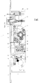
- FIG. 1 From Figures 1 and 2 is a mortise lock designed as a tubular frame lock evident, that as a self-locking, so-called panic lock shown and generally designated 1.
- the whole Training of the mortise lock is not due to the characteristics of a tubular frame lock limited and can therefore be self-locking Use panic lock.
- the main components of this self-locking Panic lock 1 are a lock plate 2, a faceplate 3, one with 4 designated lock cylinder contour, a slide 5, a bolt 6, a Cross trap 7 and a control part 8.
- switch lever 10 interchangeable part 12
- connecting piece 13 switch lever 14
- switch lever 15 switching wedges 16 and cover plate 17
- cover plate 17 for the function of the illustrative invention has no meaning; they are only intended to clarify that the invention in particular also with tubular frame locks with switchover function, i.e. with optional connection of a split nut, applicable is.
- control part 8 and cross latch 7 are closed in the lock housing during the opening process.
- the control part 8 releases a hook-like extension 23 on the slide 5, while the pin 20 on the control case shaft 19 moves into the slot 21 of the slide 5. Since there is little play between pin 20 and slot 21, it lowers seen in the image plane "the slider 5 slightly downwards. This has the consequence that the mandrel 28 of the bolt 6 shifts somewhat in the control slot 26 of the slider 5 and the bolt 6 by a small amount (about 2 to 3 mm) extends.
- the control part 8 When the door is subsequently closed, the control part 8 has the hook-like Extension 23 of the slide 5 already released so far that the slide 5 is only held by the pin 20 of the cross latch 7.
- This Pin 20 only releases the slot 21 of the slide 5 when the door is completely closed, i.e. snap the cross latch 7 into the striking plate can.
- the latch 6 is also located opposite the associated opening in the striking plate, so that the now released slide 5 preclude the bolt 6 in the striking plate can.
- the slider 5 thus locks on the pin 20 when excluded Bolt 6 and pre-closed cross latch 7 This prevents accidental entry into the lock case.
- the pin 20 Only when the slide 5 by the actuation of the cylinder bit 18, as in the figure 2, is pushed up, the pin 20 has the possibility in retract the slot 21 of the slider 5 and thus release the cross latch 7. This measure increases security.
- the possible depth of the lead of the bar 6 depends on the depth of the recess in the striking plate; should this not be sufficient can be an unwanted pushing back of the rain 6 by the im Control slot 26 of the slider 5 arranged locking points 27 prevented what is an increased security potential.
Landscapes
- Business, Economics & Management (AREA)
- Emergency Management (AREA)
- Engineering & Computer Science (AREA)
- Structural Engineering (AREA)
- Lock And Its Accessories (AREA)
Abstract
Die Erfindung betrifft ein selbstverriegelndes Panikschloß (1) mit einer federbelasteten
Kreuzfalle (7), einem schiebergesteuerten Riegel (6), einem in Längsrichtung
des Schlosses motorisch oder mechanisch bewegbaren Schieber (5) und einem
den Schieber bei rückgeschlossenem Riegel (6) arretierenden federbelaste ten
Steuerteil (8). Die Erfindung richtet sich darauf, daß die Kreuzfalle (7)
im Sinne einer Kreuzfalle einerseits unmittelbar und andererseits mittelbar
über das Steuerteil (8) den Schieber (5) derart steuert, daß beim Schließen
der Tür die Bewegung des Schiebers (5) und damit des Schloßriegels (6) erst
freigegeben werden, wenn die Kreuzfalle (7) in die ihr zugeordnete Öffnung im
Schließblech einfährt und der Riegelvorschluß erst erfolgt, wenn der Riegel (6)
der ihm zugeordneten Öffnung im Schließblech gegenüberliegt.

Description
Die Erfindung betrifft ein selbstverriegelndes Panikschloß mit einer federbelasteten Kreuzfalle, einem schiebergesteuerten Riegel, einem in Längsrichtung des Schlosses motorisch oder mechanisch bewegbaren Schieber und einem den Schieber bei rückgeschlossenem Riegel arretierenden federbelasteten Steuerteil.The invention relates to a self-locking panic lock with a spring-loaded Cross latch, a slide-controlled bolt, one in the longitudinal direction the lock motorized or mechanically movable slide and a spring-loaded locking the slide when the bolt is closed Control section.
Ein Panikschloß der vorgenannten Gattung ist durch die DE A 39 38 655 bekannt geworden. Das vorbekannte, auch durch einen Drücker oder einen Schließzylinder betätigbare Schloß besitzt einen durch eine im Türrahmen angeordnete Prallplatte in das Schloßgehäuse eindrückbaren Steuerteil, der den als Kraftübertragungsglied bezeichneten Schieber bei aufgeschlossener Tür, d.h. bei rückgeschlossenem Riegel in seiner oberen Position hält. Beim Schließen der Tür weicht der mit einem entsprechenden Haltenocken versehene Steuerteil in das Schloßgehäuse zurück, so daß durch eine entsprechende Längsbewegung des Schiebers der eigentliche Schloßriegel in das Schließblech einfahren kann.A panic lock of the aforementioned type is known from DE A 39 38 655 known. The known, also by a pusher or A lock cylinder operated lock has one by one in the door frame arranged baffle plate can be pressed into the lock housing Control part, the slider referred to as the power transmission member open door, i.e. with the bolt locked in its upper Holds position. When the door is closed, it gives way with an appropriate one Retaining cam provided control part in the lock housing, so that by a corresponding longitudinal movement of the slide the actual Lock bolt can retract into the striking plate.
Beim mechanischen oder motorischen Bewegen des Schiebers im Sinne

Bei der vorgenannten DE A 39 38 655 wird die als Kreuzfalle ausgebildete Schloßfalle über ein federbelastetes, auf den Schloßfallenschaft einwirkendes Sperrglied gehalten und damit gegen Rückschließen gesperrt. Die Entriegelung dieses Sperrgliedes erfolgt durch den Schieber; dabei ist der Abstand zwischen dem Schieber und dem die Schloßfalle sperrenden Sperrglied so bemessen, daß das Entsperren der Falle aus ihrer Sperrstellung in der Endphase des Zurückziehens des Riegels in das Schloßgehäuse erfolgt, um die auf die Seiten des Riegels wirkenden Reibungskräfte auszuschalten.In the aforementioned DE A 39 38 655, the cross trap is formed Lock latch via a spring-loaded, acting on the lock drop shaft Locking element held and thus locked against inference. The Unlocking this locking member is done by the slide; there is the Distance between the slide and the locking the latch Lock member dimensioned so that the unlocking of the trap from its locked position in the final phase of withdrawing the bolt into the lock housing takes place to the frictional forces acting on the sides of the bolt turn off.
Die DE 43 24 300 A1 beschreibt ein Antipanik-Türschloß, welches mit einem versenkbaren Taststift zur Steuerung der Falle und des Riegels ausgestattet ist. Dabei ist der Endteil des Reges über eine Riegelstange direkt mit der Nuß verbunden. Die eigentliche Steuerung geht über die Nuß, die auch den Taststift sperrt, wenn dieser in das Schloßgehäuse eingefahren ist. Gleichzeitig wird bei dem eingefahrenen Taststift auch die Falle gesperrt.DE 43 24 300 A1 describes an anti-panic door lock, which with a retractable stylus to control the latch and bolt Is provided. The end part of the rain is over a locking bar directly connected to the nut. The actual control goes over the Nut that also locks the stylus when it is inserted into the lock housing is. At the same time, the retracted stylus also Trap locked.
In der EP 0 535 497 A1 wird ebenfalls ein Panikschloß offenbart, welches mit einer Steuerfalle, einer Falle und einem auszuschließenden Riegel ausgestattet ist. Die Steuerfalle hat die Funktion, nur die Falle ausschließen zu lassen, wenn eine Betätigung der Steuerfalle erfolgt. Eine Wirkverbindung zwischen Steuerfalle, Falle und Riegel ist nicht vorhanden.A panic lock is also disclosed in EP 0 535 497 A1 with a tax trap, a trap and a bolt to be excluded Is provided. The control trap has the function of excluding the trap to let when the control trap is actuated. An active connection between the tax trap, latch and bolt is not available.
Eine Steuerfalle ist ebenfalls aus der EP 0 378 124 A1 zu entnehmen, die in Wirkverbindung über verschiedene Hebel indirekt mit der Nuß, der Falle und den durch einen Hebel betätigbaren Riegel in Wirkverbindung steht. Bei einer Betätigung der Nuß werden somit gleichzeitig der Riegel und die Falle in das Schloßgehäuse zurückgezogen, und die Steuerfalle aufgrund ihrer Federbelastung wird aus dem Schloßgehäuse herausgedrückt.A tax trap can also be found in EP 0 378 124 A1, which in operative connection via various levers indirectly with the nut, the trap and is operatively connected to the latch, which can be actuated by a lever. When the nut is actuated, the bolt and the Latch retracted into the lock housing, and the control latch due their spring load is pressed out of the lock housing.
Der Erfindung liegt die Aufgabe zugrunde, ein Schloß mit den gattungsgemäßen Merkmalen dahingehend weiterzubilden, daß beim Schließen der Tür das wirksame Vorschließen des Riegels erst dann erfolgt, wenn der Riegel sich in der Endphase des Schließvorganges gegenüber der ihm zugeordneten Ausnehmung im Schließblech befindet. Mit der erfindungsgemäßen Lösung sollen mechanische Beschädigungen am Schließblech durch vorzeitiges Vorschließen des Riegels und dadurch bedingte Verschleißerscheinungen am Riegel sowie zusätzliche seitliche Beanspruchung des Riegels und störende Geräuschentwicklung vermieden werden.The invention has for its object a castle with the generic Characteristics to the extent that when closing the The effective locking of the bolt only takes place when the Lock in the final phase of the closing process against him assigned recess is located in the striking plate. With the invention The solution is to mechanical damage to the striking plate by prematurely closing the bolt and resulting signs of wear on the bolt as well as additional lateral stress of the bolt and annoying noise can be avoided.
Die Erfindung löst die gestellte Aufgabe durch die Merkmale nach Anspruch 1. The invention solves this problem by the features according to claim 1.
Durch die mechanische Kopplung der als Kreuzfalle ausgebildeten Falle in Verbindung mit einem Steuerteil wird erreicht, daß die beim Schließen bzw. beim Öffnen der Tür der Kreuzfalle aufgezwungene Bewegung unmittelbar auf das Steuerteil übertragen wird. Dies eröffnet die Möglichkeit, sowohl die Kreuzfalle als auch das Steuerteil mit Riegelelementen zu versehen, die mit entsprechenden Riegelelementen in bzw. an einem Schieber korrespondieren. Dies bedeutet gleichzeitig, daß die Kreuzfalle nicht betätigt werden kann, wenn der Riegel vorgeschlossen ist.The mechanical coupling of the trap designed as a cross trap in Connection with a control unit is achieved when closing movement immediately when the door of the cross latch is opened is transferred to the control section. This opens up the possibility to provide both the cross latch and the control unit with locking elements, with corresponding locking elements in or on a slide correspond. This also means that the cross trap is not can be operated when the bolt is locked.
Gemäß Anspruch 2 erfolgt die Steuerung des Schiebers deshalb einerseits
unmittelbar über den Steuerfallenschaft der Kreuzfalle und andererseits
mittelbar über das von der Kreuzfalle beaufschlagte Steuerteil.According to
Im einzelnen sind hierzu am Steuerfallenschaft und am Schieber miteinander korrespondierende Riegelelemente (Anspruch 3) sowie andererseits am Steuerteil und am Schieber miteinander korrespondierende Riegelelemente (Anspruch 4) vorgesehen.The details of this are on the control case shaft and on the slide with each other corresponding locking elements (claim 3) and on the other hand corresponding locking elements on the control part and on the slide (Claim 4) provided.
Die Übertragung der der Kreuzfalle aufgezwungenen Bewegung erfolgt vorteilhaft über einen Riegelfortsatz des Steuerteils, das sich unmittelbar an der Kreuzfalle abstützt (Anspruch 5).The movement of the cross trap is transmitted advantageous about a bolt extension of the control part, which is immediate supported on the cross trap (claim 5).
Da beim Schließen der Tür Kreuzfalle und Steuerteil nahezu gleichzeitig rückgeschlossen, d.h. in das Schloßgehäuse eingefahren werden, muß sichergestellt sein, daß während dieses Einfahrvorganges der Schieber noch in seiner den Riegel (Schloßriegel) arretierenden Position gehalten wird. Andererseits muß jedoch sichergestellt sein, daß während des Schließens der Tür der Schieber von dem Steuerteil freigegeben wird, damit nach Beendigung des Schließvorganges mit dem Vorschluß der Kreuzfalle in das Schließblech auch der Riegel in das Schließblech vorgeschlossen werden kann.Because the cross latch and control unit close almost simultaneously when the door is closed inferred, i.e. must be retracted into the lock housing be sure that during this retraction of the slide still held in its locking position becomes. On the other hand, however, it must be ensured that during the Closing the door the slide is released by the control part so after completion of the closing process with the conclusion of Cross latch in the striking plate also pre-locked the bolt in the striking plate can be.
Zu diesem Zweck wird gemäß Anspruch 6 vorgeschlagen, daß eine Bemessung
der korrespondierenden Riegelelemente am Steuerteil und an
der Kreuzfalle einerseits sowie am Schieber andererseits derart erfolgt,
daß beim Rückschluß des Steuerteils und der Kreuzfalle in das Schloßgehäuse
die Verriegelung zwischen Kreuzfalle und Schieber aktiviert und die
bestehende Verriegelung zwischen Steuerteil und Schieber zeitlich verzögert
nach Aktivierung der Verriegelung zwischen Kreuzfalle und Schieber
freigegeben wird. Dabei dringt der Zapfen am Steuerfallenschaft in einen
Schlitz des Schiebers ein und hält den Schieber in seiner oberen Position,
wobei lediglich ein ganz geringfügiges Absinken des Schiebers nach Maßgabe
des Spiels zwischen Schlitz und Zapfen erfolgt, was einen Riegelvorschluß
um etwa 2 bis 3 mm zur Folge hat. Dieser Riegelvorschluß ist nicht
störend, weil dies im Rahmen des Spiels zwischen Stulp und Schließblech
liegt.For this purpose it is proposed according to
Wie vorbeschrieben, wird die Verriegelung zwischen der Kreuzfalle und dem Schieber erst beim Ausfahren der Kreuzfalle in das Schließblech freigegeben, so daß bis dahin keine Berührung zwischen Riegel und Schließblech besteht.As previously described, the latch between the cross latch and the slide is only released when the cross latch is extended into the striking plate, until then no contact between bolt and striking plate consists.
Bei vorgeschlossenem Riegel befindet sich der Schieber in seiner unteren Position. Erfindungsgemäß ist am Schieber eine Anschlagkante vorgesehen, welche an dem am Fallenschaft der Kreuzfalle angeordneten Zapfen anliegt und somit die Kreuzfalle gegen Rückschluß in das Schloßgehäuse sperrt (Anspruch 8).When the bolt is locked, the slide is in its lower one Position. According to the invention, a stop edge is provided on the slide, which on the pin arranged on the drop shaft of the cross trap is present and thus the cross latch against inference in the lock housing blocks (claim 8).
In vorteilhafter Ausgestaltung der Erfindung weist der Steuerschlitz des Schiebers mehrere Raststellen für einen Dorn des Riegels auf; mit dieser Maßnahme kann ein ungewolltes Rückschließen des Riegels in das Schloßgehäuse auch dann verhindert werden, wenn der Riegel beispielsweise aufgrund einer fehlerhaften Ausnehmung im Schließblech nicht voll ausgeschlossen ist.In an advantageous embodiment of the invention, the control slot of the Slider several rest stops for a spike of the bolt; with this Measure can include an unwanted closing of the bolt in the Lock housing can also be prevented when the bolt, for example not full due to a faulty recess in the striking plate is excluded.
Mit der erfindungsgemäßen Lösung wird ein während des Schließvorganges der Tür verzögertes Vorschließen des Riegels in das Schließblech wie bei einem selbstverriegelnden Schloß erreicht. Die besondere Ausgestaltung der erfindungsgemäßen Lösung mit der mechanischen Kopplung zwischen Kreuzfalle und Steuerteil in Verbindung mit entsprechenden Riegelelementen am Schieber ermöglicht eine sehr schmale Bauweise des gesamten Schlosses, so daß es auch als Rohrrahmenschloß einsetzbar ist und in das Schloßgehäuse weitere vorteilhafte Funktionen wie Antipanikfunktion oder Umschaltfunktion (d.h. wahlweise Verbindung oder Trennung von Nußhälften einer geteilten Nuß) integriert werden können.With the solution according to the invention is a during the closing process the door delayed closing the bolt in the striking plate like reached with a self-locking lock. The special design the solution according to the invention with the mechanical coupling between Cross latch and control unit in connection with corresponding locking elements on the slide allows a very narrow construction of the whole Lock, so that it can also be used as a tubular frame lock and other advantageous functions such as anti-panic function in the lock housing or switching function (i.e. either connection or disconnection halves of a split nut) can be integrated.
Die Erfindung wird nachfolgend anhand eines möglichen Ausführungsbeispieles näher erläutert. Es zeigen:
- Figur 1:
- eine Ansicht auf das Schloßblech bei geöffneter Schloßdecke und vorgeschlossenem Riegel
- Figur 2:
- Ansicht gemäß Figur 1 bei rückgeschlossenem Riegel
- Figur 3:
- den Schieber
- Figur 4:
- das Steuerteil
- Figure 1:
- a view of the lock plate with the lock cover open and the bolt locked
- Figure 2:
- View according to Figure 1 with the bolt closed
- Figure 3:
- the slider
- Figure 4:
- the control section
Aus den Figuren 1 und 2 ist ein als Rohrrahmenschloß ausgebildetes Einsteckschloß
ersichtlich, das als selbstverriegelndes, sogenanntes Panikschloß
dargestellt und allgemein mit 1 bezeichnet worden ist. Die gesamte
Ausbildung des Einsteckschlosses ist nicht auf die Merkmale eines Rohrrahmenschlosses
begrenzt und läßt sich somit für jedes selbstverriegelnde
Panikschloß anwenden. Die wesentlichen Bauteile dieses selbstverriegelnden
Panikschlosses 1 sind ein Schloßblech 2, eine Stulp 3, eine mit 4
bezeichnete Schließzylinderkontur, ein Schieber 5, ein Riegel 6, eine
Kreuzfalle 7 und ein Steuerteil 8.From Figures 1 and 2 is a mortise lock designed as a tubular frame lock
evident, that as a self-locking, so-called panic lock
shown and generally designated 1. The whole
Training of the mortise lock is not due to the characteristics of a tubular frame lock
limited and can therefore be self-locking
Use panic lock. The main components of this self-locking
Panic lock 1 are a
Die weiter in den Figuren 1 und 2 dargestellten Bauteile wie Umschalthebel
10, Wechselteil 12, Verbindungsstück 13, Einschalthebel 14, Ausschalthebel
15, Schaltkeile 16 und Abdeckblech 17 haben für die Funktion der zu
erläuternden Erfindung keine Bedeutung; sie sollen lediglich verdeutlichen,
daß die Erfindung insbesondere auch bei Rohrrahmenschlössern mit Umschaltfunktion,
d.h. mit wahlweiser Verbindung einer geteilten Nuß, anwendbar
ist.The components shown in Figures 1 and 2 such as
In der Darstellung gemäß Figur 1 ist die Situation bei geschlossener Tür
dargestellt, d. h. der Riegel 6 ist vorgeschlossen. Der Schieber 5 befindet
sich in seiner in der Bildebene unteren Position; dabei ist der Riegel 6 am
Riegelrückschluß durch den im Steuerschlitz 26 des Schiebers 5 eingerasteten
Dorn 28 des Riegels 6 gehindert. Ebenso ist die Kreuzfalle 7 durch
die an einem Zapfen 20 eines Steuerfallenschaftes 19 anliegenden Anschlagkante
25 des Schiebers 5 gegen Rückschluß in das Schloßgehäuse
gesperrt. Zwischen dem Steuerteil 8 und dem Schieber 5 besteht keine
Verbindung.1 shows the situation when the door is closed
shown, d. H. the
Bei
In der angehobenen Position des Schiebers 5 hinterfaßt ein hakenartiger
Fortsatz 23 des Schiebers 5 einen Haltenocken 22 am Steuerteil 8.
Gleichzeitig befindet sich ein Schlitz 21 im Schieber 5 in einer Position, in
der er dem Zapfen 20 am Steuerfallenschaft 19 der Kreuzfalle 7 gegenüberliegt.
Während die federbelastete Verriegelung durch einen Haltenocken
22 am Steuerteil 8 eingerastet ist, befindet sich der Zapfen 20 am
Steuerfallenschaft 19 außerhalb des Eingriffs mit dem Schlitz 21 des
Schiebers 5. Der Riegel 6 befindet sich nunmehr in der in das Schloßgehäuse
rückgeschlossenen Position. Das Steuerteil 8 stützt sich mit seinem
Riegelfortsatz 24 unmittelbar an der Kreuzfalle 7 ab (siehe auch Figur 4).
Die Kreuzfalle 7 ist ebenfalls durch eine Feder 31 belastet.In the raised position of the
Wird nach dem Aufschließen der Tür die Tür nunmehr geöffnet
(beispielsweise durch Aufstoßen oder Aufziehen), werden während des
Öffnungsvorganges Steuerteil 8 und Kreuzfalle 7 in das Schloßgehäuse
rückgeschlossen. Dabei gibt das Steuerteil 8 einen hakenartigen Fortsatz
23 am Schieber 5 frei, während gleichzeitig der Zapfen 20 am Steuerfallenschaft
19 in den Schlitz 21 des Schiebers 5 einfährt. Da zwischen
Zapfen 20 und Schlitz 21 ein geringes Spiel besteht senkt sich
Beim folgenden Schließen der Tür hat das Steuerteil 8 den hakenartigen
Fortsatz 23 des Schiebers 5 bereits soweit freigegeben, daß der Schieber
5 lediglich noch durch den Zapfen 20 der Kreuzfalle 7 gehalten wird. Dieser
Zapfen 20 gibt den Schlitz 21 des Schiebers 5 jedoch erst frei, wenn
die Tür ganz geschlossen ist, d.h. die Kreuzfalle 7 in das Schließblech einrasten
kann. Zu diesem Zeitpunkt befindet sich jedoch auch der Riegel 6
gegenüber der ihm zugeordneten Öffnung im Schließblech, so daß der
nunmehr freigegebene Schieber 5 den Riegel 6 in das Schließblech vorschließen
kann. Der Schieber 5 sperrt somit über den Zapfen 20 bei ausgeschlossenem
Riegel 6 und gleichzeitig vorgeschlossener Kreuzfalle 7
diese gegen unbeabsichtigtes Einfahren in den Schloßkasten. Erst wenn
der Schieber 5 durch die Betätigung des Zylinderbartes 18, wie in der Figur
2 dargestellt, hochgeschoben wird, hat der Zapfen 20 die Möglichkeit, in
den Schlitz 21 des Schiebers 5 einzufahren und damit die Kreuzfalle 7 freizugeben.
Durch diese Maßnahme wird eine erhöhte Sicherheit erreicht.
Die mögliche Tiefe des Vorschlusses des Riegels 6 ist dabei abhängig von
der Tiefe der Ausnehmung im Schließblech; sollte diese nicht ausreichend
sein, kann ein ungewolltes Zurückdrücken des Reges 6 durch die im
Steuerschlitz 26 des Schiebers 5 angeordneten Raststellen 27 verhindert
werden, was ein erhöhtes Sicherheitspotential darstellt.When the door is subsequently closed, the
Aus den Figuren 1 und 2 ist weiterhin ersichtlich, daß über die Drückernuß
9 ein Panikhebel 11 bedient werden kann, über den der Schieber 5 von
der Türinnenseite angehoben und der Riegel 6 in das Schloßgehäuse
rückgeschlossen werden kann.From Figures 1 and 2 it can also be seen that the handle nut
9 a
Die vorbeschriebene Wirkungsweise des Schlosses 1 ist anhand einer
Kreuzfalle 7 beschrieben worden, wobei der erfindungsgemäße Gedanke
auch mit jeder andersartig gestalteten Fallenausbildung realisiert werden
kann. Die Funktion des Schiebers 5 kann auch entgegen der Beschreibung
motorisch ausgelöst werden. The above-described mode of operation of the lock 1 is based on a
- 11
- PanikschloßPanic lock
- 22nd
- SchloßblechLock plate
- 33rd
- StulpForend
- 44th
- SchließzylinderkonturLock cylinder contour
- 55
- SchieberSlider
- 66
- Riegelbars
- 77
- KreuzfalleCross trap
- 88th
- SteuerteilControl section
- 99
- DrückernußTrigger nut
- 1010th
- UmschalthebelShift lever
- 1111
- PanikhebelPanic lever
- 1111
- WechselteilExchange part
- 1313
- VerbindungsstückConnector
- 1414
- EinschalthebelEngagement lever
- 1515
- AusschalthebelSwitch-off lever
- 1616
- SchaltkeilShifting wedge
- 1717th
- AbdeckblechCover plate
- 1818th
- ZylinderbartCylinder beard
- 1919th
- SteuerfallenschaftTax liability
- 2020th
- Zapfen am SchieberfallenschaftPin on the slide drop shaft
- 2121
- Schlitz im SchieberSlit in the slider
- 2222
- Haltenocken SteuerteilHolding cam control part
- 2323
- hakenartiger Fortsatz am Schieberhook-like extension on the slide
- 2424th
- Riegelfortsatz des SteuerteilsBolt extension of the control part
- 2525th
- Anschlagkante am SchieberStop edge on the slide
- 2626
- Steuerschlitz des SchiebersControl slit of the slide
- 2727
- Raststellen im SteuerschlitzResting points in the control slot
- 2828
- Dorn des RiegelsThorn of the bolt
- 2929
- Anschlagattack
- 3030th
- RückholfederReturn spring
- 3131
- Federfeather
Claims (9)
Applications Claiming Priority (2)
| Application Number | Priority Date | Filing Date | Title |
|---|---|---|---|
| DE19626745A DE19626745C1 (en) | 1996-07-03 | 1996-07-03 | Self-securing panic door lock with spring-loaded cruciform latch |
| DE19626745 | 1996-07-03 |
Publications (3)
| Publication Number | Publication Date |
|---|---|
| EP0816603A2 true EP0816603A2 (en) | 1998-01-07 |
| EP0816603A3 EP0816603A3 (en) | 1998-07-15 |
| EP0816603B1 EP0816603B1 (en) | 2003-11-05 |
Family
ID=7798791
Family Applications (1)
| Application Number | Title | Priority Date | Filing Date |
|---|---|---|---|
| EP97110463A Expired - Lifetime EP0816603B1 (en) | 1996-07-03 | 1997-06-26 | Self-locking antipanic lock |
Country Status (3)
| Country | Link |
|---|---|
| EP (1) | EP0816603B1 (en) |
| AT (1) | ATE253678T1 (en) |
| DE (2) | DE19626745C1 (en) |
Cited By (5)
| Publication number | Priority date | Publication date | Assignee | Title |
|---|---|---|---|---|
| WO2006070025A1 (en) * | 2004-12-23 | 2006-07-06 | Talleres De Escoriaza, S.A. | Mortise lock with automatic bolt extension |
| ES2257134A1 (en) * | 2003-10-13 | 2006-07-16 | Talleres De Escoriaza, S.A. | Automatic lock device for door handles, has trigger support with blocking sections to block vertical sliding movement of handle retainer which has hooks coupled to retainer latch and to trigger portion to block movement of handle retainer |
| EP2717508A1 (en) | 2012-10-05 | 2014-04-09 | Fujitsu Limited | MIMO wireless communication system |
| EP2757731A1 (en) | 2013-01-21 | 2014-07-23 | Fujitsu Limited | MIMO Wireless Communication System |
| EP2754801A3 (en) * | 2013-01-11 | 2015-07-22 | Wilh. Schlechtendahl & Söhne GmbH & Co. KG | Strike box or mortise lock |
Families Citing this family (13)
| Publication number | Priority date | Publication date | Assignee | Title |
|---|---|---|---|---|
| DE19749023B4 (en) * | 1997-11-06 | 2004-03-25 | Wilka Schließtechnik GmbH | Lock for doors, windows or the like |
| DE10028176A1 (en) * | 2000-06-09 | 2001-12-13 | Michael Dorn | Self-operating deadlock for e.g. hotels includes blocking device operated by remote control, to block or release latch operation |
| FI114497B (en) | 2003-05-14 | 2004-10-29 | Abloy Oy | Arrangement for controlling the locking of the slanting axle in the door lock |
| DE102006060448A1 (en) * | 2006-12-19 | 2008-06-26 | Dorma Gmbh + Co. Kg | Self-locking panic lock |
| DE102006060450A1 (en) * | 2006-12-19 | 2008-06-26 | Dorma Gmbh + Co. Kg | Self-locking, electromechanical panic lock |
| DE102006060451A1 (en) * | 2006-12-19 | 2008-06-26 | Dorma Gmbh + Co. Kg | Self-locking panic lock, as well as a method for operating a self-locking panic lock |
| DE102006060449A1 (en) * | 2006-12-19 | 2008-06-26 | Dorma Gmbh + Co. Kg | Self-locking panic lock |
| WO2009060483A1 (en) * | 2007-11-07 | 2009-05-14 | Assa Abloy Italia S.P.A. | Lock |
| IT1394394B1 (en) * | 2008-08-06 | 2012-06-15 | Iseo Serrature Spa | LOCK WITH MULTIPLE CLOSING POINTS |
| DE202011103779U1 (en) | 2011-07-06 | 2012-10-15 | Maco Technologie Gmbh | lock |
| DE102012101658A1 (en) | 2012-02-29 | 2013-08-29 | Dorma Gmbh + Co. Kg | lock |
| GB201707144D0 (en) | 2017-05-04 | 2017-06-21 | Era Home Security Ltd | Locking assembly |
| AT17862U1 (en) | 2022-01-24 | 2023-05-15 | Roto Frank Fenster Und Tuertechnologie Gmbh | automatic lock |
Family Cites Families (7)
| Publication number | Priority date | Publication date | Assignee | Title |
|---|---|---|---|---|
| FI83802C (en) * | 1988-11-25 | 1991-08-26 | Abloy Security Ltd Oy | ELEKTROMEKANISKT DOERRLAOS. |
| IT1233297B (en) * | 1989-01-11 | 1992-03-26 | Italiana Serrature Affini | LATCH AND LATCH LOCK WITH PANIC OPENING |
| DE4110556C5 (en) * | 1991-03-30 | 2008-02-07 | Karl Fliether Gmbh & Co. Kg | By means of pusher and / or lock cylinder to be operated lock |
| IT1253045B (en) * | 1991-10-01 | 1995-07-10 | Italiana Serrature Affini | IMPROVEMENTS IN THE LOCKS TO BE INSERTED INCLUDING LATCH AND LATCH AND EQUIPPED WITH PANIC DEVICE |
| ES2066673B1 (en) * | 1992-07-20 | 1996-10-16 | Talleres Escoriaza Sa | PERFECTED ANTI-PANIC LOCK. |
| ES2115191T3 (en) * | 1994-02-21 | 1998-06-16 | Hellmuller & Zingg Ag | DOOR LOCK. |
| DE19620908C1 (en) * | 1996-05-24 | 1997-08-21 | Dorma Gmbh & Co Kg | Self-locking emergency lock |
-
1996
- 1996-07-03 DE DE19626745A patent/DE19626745C1/en not_active Expired - Fee Related
-
1997
- 1997-06-26 EP EP97110463A patent/EP0816603B1/en not_active Expired - Lifetime
- 1997-06-26 AT AT97110463T patent/ATE253678T1/en not_active IP Right Cessation
- 1997-06-26 DE DE59710939T patent/DE59710939D1/en not_active Expired - Lifetime
Cited By (7)
| Publication number | Priority date | Publication date | Assignee | Title |
|---|---|---|---|---|
| ES2257134A1 (en) * | 2003-10-13 | 2006-07-16 | Talleres De Escoriaza, S.A. | Automatic lock device for door handles, has trigger support with blocking sections to block vertical sliding movement of handle retainer which has hooks coupled to retainer latch and to trigger portion to block movement of handle retainer |
| ES2257134B1 (en) * | 2003-10-13 | 2007-02-16 | Talleres De Escoriaza, S.A. | A LOCK OF EMBUTIR WITH AUTOMATIC DEPARTURE OF PALANCA. |
| WO2006070025A1 (en) * | 2004-12-23 | 2006-07-06 | Talleres De Escoriaza, S.A. | Mortise lock with automatic bolt extension |
| EP2717508A1 (en) | 2012-10-05 | 2014-04-09 | Fujitsu Limited | MIMO wireless communication system |
| EP2754801A3 (en) * | 2013-01-11 | 2015-07-22 | Wilh. Schlechtendahl & Söhne GmbH & Co. KG | Strike box or mortise lock |
| EP2754801B1 (en) | 2013-01-11 | 2016-10-12 | Wilh. Schlechtendahl & Söhne GmbH & Co. KG | Strike box or mortise lock |
| EP2757731A1 (en) | 2013-01-21 | 2014-07-23 | Fujitsu Limited | MIMO Wireless Communication System |
Also Published As
| Publication number | Publication date |
|---|---|
| ATE253678T1 (en) | 2003-11-15 |
| DE59710939D1 (en) | 2003-12-11 |
| DE19626745C1 (en) | 1997-10-16 |
| EP0816603B1 (en) | 2003-11-05 |
| EP0816603A3 (en) | 1998-07-15 |
Similar Documents
| Publication | Publication Date | Title |
|---|---|---|
| EP1932989B1 (en) | Locking device for doors, windows or similar, in particular an espagnolette lock with panic function and multi-point locking | |
| EP0816603B1 (en) | Self-locking antipanic lock | |
| DE102006059568B4 (en) | Locking system for doors, windows or the like, in particular espagnolette lock with panic function and multipoint locking | |
| DE4028897C1 (en) | Motor vehicle boot flap lock - has spring loaded detent to prevent bolt being set if lid is open | |
| EP0521262A1 (en) | Lock | |
| EP0945572B1 (en) | Door lock arrangement, preferably espagnolette lock | |
| DE102004012108B4 (en) | Espagnolette lock for doors, windows or the like with panic function and multipoint locking | |
| EP2754798B1 (en) | Door locking device for a door with at least one door leaf | |
| DE3425565A1 (en) | DRIVE ROD LOCK | |
| EP2072725A2 (en) | Espagnolette locking device | |
| EP0653535B1 (en) | Lock | |
| DE102021118277A1 (en) | motor vehicle lock | |
| EP2339096B1 (en) | Connecting rod lock with panic function and multiple locking | |
| EP0779404A2 (en) | Security lock | |
| EP1617019B1 (en) | Electromechanical door lock | |
| DE102015000606A1 (en) | Locking device for a pivotally mounted wing | |
| EP0779403B1 (en) | Security lock | |
| DE3931101A1 (en) | Automatic lock for door - extends bolt automatically on entering lock plate | |
| EP1739257B1 (en) | Lock | |
| DE202007016091U1 (en) | Espagnolette | |
| EP3748109A1 (en) | Locking device | |
| EP2998475A1 (en) | Day lever for a passively wing lock | |
| EP1936076B1 (en) | Self-locking anti panic lock | |
| EP0675250B1 (en) | Lock, in particular espagnolette or similar | |
| WO1990004694A1 (en) | Automatic lock |
Legal Events
| Date | Code | Title | Description |
|---|---|---|---|
| PUAI | Public reference made under article 153(3) epc to a published international application that has entered the european phase |
Free format text: ORIGINAL CODE: 0009012 |
|
| ITCL | It: translation for ep claims filed |
Representative=s name: DE DOMINICIS & MAYER S.R.L. |
|
| GBC | Gb: translation of claims filed (gb section 78(7)/1977) | ||
| EL | Fr: translation of claims filed | ||
| TCNL | Nl: translation of patent claims filed | ||
| PUAL | Search report despatched |
Free format text: ORIGINAL CODE: 0009013 |
|
| AK | Designated contracting states |
Kind code of ref document: A3 Designated state(s): AT BE CH DE DK ES FI FR GB GR IE IT LI LU MC NL PT SE |
|
| AKX | Designation fees paid | ||
| RBV | Designated contracting states (corrected) | ||
| RBV | Designated contracting states (corrected) |
Designated state(s): AT BE CH DE DK ES FI FR GB GR IE IT LI LU NL SE |
|
| 17P | Request for examination filed |
Effective date: 19990115 |
|
| RBV | Designated contracting states (corrected) |
Designated state(s): AT BE CH DE FI FR GB IT LI LU NL SE |
|
| 17Q | First examination report despatched |
Effective date: 20010214 |
|
| GRAH | Despatch of communication of intention to grant a patent |
Free format text: ORIGINAL CODE: EPIDOS IGRA |
|
| GRAS | Grant fee paid |
Free format text: ORIGINAL CODE: EPIDOSNIGR3 |
|
| GRAA | (expected) grant |
Free format text: ORIGINAL CODE: 0009210 |
|
| AK | Designated contracting states |
Kind code of ref document: B1 Designated state(s): AT BE CH DE FI FR GB IT LI LU NL SE |
|
| REG | Reference to a national code |
Ref country code: GB Ref legal event code: FG4D Free format text: NOT ENGLISH |
|
| REG | Reference to a national code |
Ref country code: CH Ref legal event code: EP |
|
| GBT | Gb: translation of ep patent filed (gb section 77(6)(a)/1977) |
Effective date: 20031105 |
|
| REF | Corresponds to: |
Ref document number: 59710939 Country of ref document: DE Date of ref document: 20031211 Kind code of ref document: P |
|
| REG | Reference to a national code |
Ref country code: SE Ref legal event code: TRGR |
|
| PGFP | Annual fee paid to national office [announced via postgrant information from national office to epo] |
Ref country code: NL Payment date: 20040514 Year of fee payment: 8 |
|
| ET | Fr: translation filed | ||
| PLBQ | Unpublished change to opponent data |
Free format text: ORIGINAL CODE: EPIDOS OPPO |
|
| PLBI | Opposition filed |
Free format text: ORIGINAL CODE: 0009260 |
|
| 26 | Opposition filed |
Opponent name: IKON AKTIENGESELLSCHAFT PRAEZISIONSTECHNIK Effective date: 20040805 Opponent name: ABLOY OY Effective date: 20040805 Opponent name: EFF-EFF FRITZ FUSS GMBH & CO. KG AA Effective date: 20040805 |
|
| PLAX | Notice of opposition and request to file observation + time limit sent |
Free format text: ORIGINAL CODE: EPIDOSNOBS2 |
|
| NLR1 | Nl: opposition has been filed with the epo |
Opponent name: IKON AKTIENGESELLSCHAFT PRAEZISIONSTECHNIK Opponent name: ABLOY OY Opponent name: EFF-EFF FRITZ FUSS GMBH & CO. KG AA |
|
| RTI2 | Title (correction) |
Free format text: SELF-LOCKING ANTIPANIC LOCK |
|
| PLAX | Notice of opposition and request to file observation + time limit sent |
Free format text: ORIGINAL CODE: EPIDOSNOBS2 |
|
| PLAX | Notice of opposition and request to file observation + time limit sent |
Free format text: ORIGINAL CODE: EPIDOSNOBS2 |
|
| PLAB | Opposition data, opponent's data or that of the opponent's representative modified |
Free format text: ORIGINAL CODE: 0009299OPPO |
|
| PLAQ | Examination of admissibility of opposition: information related to despatch of communication + time limit deleted |
Free format text: ORIGINAL CODE: EPIDOSDOPE2 |
|
| PLAR | Examination of admissibility of opposition: information related to receipt of reply deleted |
Free format text: ORIGINAL CODE: EPIDOSDOPE4 |
|
| PLBP | Opposition withdrawn |
Free format text: ORIGINAL CODE: 0009264 |
|
| PLBQ | Unpublished change to opponent data |
Free format text: ORIGINAL CODE: EPIDOS OPPO |
|
| R26 | Opposition filed (corrected) |
Opponent name: IKON AKTIENGESELLSCHAFT PRAEZISIONSTECHNIK Effective date: 20040805 Opponent name: EFF-EFF FRITZ FUSS GMBH & CO. KG AA Effective date: 20040805 |
|
| NLR1 | Nl: opposition has been filed with the epo |
Opponent name: IKON AKTIENGESELLSCHAFT PRAEZISIONSTECHNIK Opponent name: EFF-EFF FRITZ FUSS GMBH & CO. KG AA |
|
| PLBP | Opposition withdrawn |
Free format text: ORIGINAL CODE: 0009264 |
|
| PLBB | Reply of patent proprietor to notice(s) of opposition received |
Free format text: ORIGINAL CODE: EPIDOSNOBS3 |
|
| PG25 | Lapsed in a contracting state [announced via postgrant information from national office to epo] |
Ref country code: NL Free format text: LAPSE BECAUSE OF NON-PAYMENT OF DUE FEES Effective date: 20060101 |
|
| NLV4 | Nl: lapsed or anulled due to non-payment of the annual fee |
Effective date: 20060101 |
|
| PLBP | Opposition withdrawn |
Free format text: ORIGINAL CODE: 0009264 |
|
| PLBD | Termination of opposition procedure: decision despatched |
Free format text: ORIGINAL CODE: EPIDOSNOPC1 |
|
| PLBM | Termination of opposition procedure: date of legal effect published |
Free format text: ORIGINAL CODE: 0009276 |
|
| STAA | Information on the status of an ep patent application or granted ep patent |
Free format text: STATUS: OPPOSITION PROCEDURE CLOSED |
|
| 27C | Opposition proceedings terminated |
Effective date: 20060930 |
|
| PGFP | Annual fee paid to national office [announced via postgrant information from national office to epo] |
Ref country code: CH Payment date: 20070615 Year of fee payment: 11 |
|
| PGFP | Annual fee paid to national office [announced via postgrant information from national office to epo] |
Ref country code: AT Payment date: 20070618 Year of fee payment: 11 |
|
| PGFP | Annual fee paid to national office [announced via postgrant information from national office to epo] |
Ref country code: LU Payment date: 20070621 Year of fee payment: 11 |
|
| PLAB | Opposition data, opponent's data or that of the opponent's representative modified |
Free format text: ORIGINAL CODE: 0009299OPPO |
|
| REG | Reference to a national code |
Ref country code: CH Ref legal event code: PL |
|
| PG25 | Lapsed in a contracting state [announced via postgrant information from national office to epo] |
Ref country code: AT Free format text: LAPSE BECAUSE OF NON-PAYMENT OF DUE FEES Effective date: 20080626 |
|
| PG25 | Lapsed in a contracting state [announced via postgrant information from national office to epo] |
Ref country code: LI Free format text: LAPSE BECAUSE OF NON-PAYMENT OF DUE FEES Effective date: 20080630 Ref country code: CH Free format text: LAPSE BECAUSE OF NON-PAYMENT OF DUE FEES Effective date: 20080630 |
|
| PLAB | Opposition data, opponent's data or that of the opponent's representative modified |
Free format text: ORIGINAL CODE: 0009299OPPO |
|
| PG25 | Lapsed in a contracting state [announced via postgrant information from national office to epo] |
Ref country code: LU Free format text: LAPSE BECAUSE OF NON-PAYMENT OF DUE FEES Effective date: 20080626 |
|
| PGFP | Annual fee paid to national office [announced via postgrant information from national office to epo] |
Ref country code: GB Payment date: 20140618 Year of fee payment: 18 |
|
| PGFP | Annual fee paid to national office [announced via postgrant information from national office to epo] |
Ref country code: SE Payment date: 20140618 Year of fee payment: 18 Ref country code: IT Payment date: 20140627 Year of fee payment: 18 Ref country code: FI Payment date: 20140611 Year of fee payment: 18 |
|
| PGFP | Annual fee paid to national office [announced via postgrant information from national office to epo] |
Ref country code: BE Payment date: 20140620 Year of fee payment: 18 |
|
| PGFP | Annual fee paid to national office [announced via postgrant information from national office to epo] |
Ref country code: FR Payment date: 20140619 Year of fee payment: 18 |
|
| REG | Reference to a national code |
Ref country code: DE Ref legal event code: R081 Ref document number: 59710939 Country of ref document: DE Owner name: DORMAKABA DEUTSCHLAND GMBH, DE Free format text: FORMER OWNER: DORMA GMBH + CO. KG, 58256 ENNEPETAL, DE Effective date: 20141211 Ref country code: DE Ref legal event code: R081 Ref document number: 59710939 Country of ref document: DE Owner name: DORMA DEUTSCHLAND GMBH, DE Free format text: FORMER OWNER: DORMA GMBH + CO. KG, 58256 ENNEPETAL, DE Effective date: 20141211 |
|
| REG | Reference to a national code |
Ref country code: FR Ref legal event code: CJ Effective date: 20150206 Ref country code: FR Ref legal event code: CA Effective date: 20150206 |
|
| REG | Reference to a national code |
Ref country code: DE Ref legal event code: R082 Ref document number: 59710939 Country of ref document: DE Representative=s name: BALDER IP LAW, S.L., ES |
|
| PG25 | Lapsed in a contracting state [announced via postgrant information from national office to epo] |
Ref country code: FI Free format text: LAPSE BECAUSE OF NON-PAYMENT OF DUE FEES Effective date: 20150626 Ref country code: IT Free format text: LAPSE BECAUSE OF NON-PAYMENT OF DUE FEES Effective date: 20150626 |
|
| REG | Reference to a national code |
Ref country code: SE Ref legal event code: EUG |
|
| GBPC | Gb: european patent ceased through non-payment of renewal fee |
Effective date: 20150626 |
|
| PG25 | Lapsed in a contracting state [announced via postgrant information from national office to epo] |
Ref country code: SE Free format text: LAPSE BECAUSE OF NON-PAYMENT OF DUE FEES Effective date: 20150627 |
|
| REG | Reference to a national code |
Ref country code: FR Ref legal event code: ST Effective date: 20160229 |
|
| PG25 | Lapsed in a contracting state [announced via postgrant information from national office to epo] |
Ref country code: GB Free format text: LAPSE BECAUSE OF NON-PAYMENT OF DUE FEES Effective date: 20150626 |
|
| PG25 | Lapsed in a contracting state [announced via postgrant information from national office to epo] |
Ref country code: FR Free format text: LAPSE BECAUSE OF NON-PAYMENT OF DUE FEES Effective date: 20150630 |
|
| PGFP | Annual fee paid to national office [announced via postgrant information from national office to epo] |
Ref country code: DE Payment date: 20160621 Year of fee payment: 20 |
|
| REG | Reference to a national code |
Ref country code: DE Ref legal event code: R082 Ref document number: 59710939 Country of ref document: DE Representative=s name: BALDER IP LAW, S.L., ES Ref country code: DE Ref legal event code: R081 Ref document number: 59710939 Country of ref document: DE Owner name: DORMAKABA DEUTSCHLAND GMBH, DE Free format text: FORMER OWNER: DORMA DEUTSCHLAND GMBH, 58256 ENNEPETAL, DE |
|
| REG | Reference to a national code |
Ref country code: DE Ref legal event code: R071 Ref document number: 59710939 Country of ref document: DE |
|
| PG25 | Lapsed in a contracting state [announced via postgrant information from national office to epo] |
Ref country code: BE Free format text: LAPSE BECAUSE OF NON-PAYMENT OF DUE FEES Effective date: 20150630 |