EP0816618A1 - Paroi de séparation constituée d'éléments pouvant être entraínés - Google Patents
Paroi de séparation constituée d'éléments pouvant être entraínés Download PDFInfo
- Publication number
- EP0816618A1 EP0816618A1 EP97109251A EP97109251A EP0816618A1 EP 0816618 A1 EP0816618 A1 EP 0816618A1 EP 97109251 A EP97109251 A EP 97109251A EP 97109251 A EP97109251 A EP 97109251A EP 0816618 A1 EP0816618 A1 EP 0816618A1
- Authority
- EP
- European Patent Office
- Prior art keywords
- drive belt
- room partition
- locking
- partition according
- roller carriage
- Prior art date
- Legal status (The legal status is an assumption and is not a legal conclusion. Google has not performed a legal analysis and makes no representation as to the accuracy of the status listed.)
- Granted
Links
- 238000000638 solvent extraction Methods 0.000 title 1
- 238000005192 partition Methods 0.000 claims abstract description 24
- 238000010168 coupling process Methods 0.000 claims abstract description 17
- 230000008878 coupling Effects 0.000 claims abstract description 15
- 238000005859 coupling reaction Methods 0.000 claims abstract description 15
- 230000006835 compression Effects 0.000 claims description 5
- 238000007906 compression Methods 0.000 claims description 5
- 229910000831 Steel Inorganic materials 0.000 claims description 2
- 239000010959 steel Substances 0.000 claims description 2
- 238000000034 method Methods 0.000 description 7
- 230000008569 process Effects 0.000 description 6
- 230000001133 acceleration Effects 0.000 description 3
- 230000008901 benefit Effects 0.000 description 3
- 238000010276 construction Methods 0.000 description 2
- 230000003993 interaction Effects 0.000 description 2
- 239000000725 suspension Substances 0.000 description 2
- 230000009471 action Effects 0.000 description 1
- 230000005540 biological transmission Effects 0.000 description 1
- 230000001419 dependent effect Effects 0.000 description 1
- 238000011161 development Methods 0.000 description 1
- 230000018109 developmental process Effects 0.000 description 1
- 230000000694 effects Effects 0.000 description 1
- 230000036039 immunity Effects 0.000 description 1
- 210000001503 joint Anatomy 0.000 description 1
- 230000007257 malfunction Effects 0.000 description 1
Images



Classifications
-
- E—FIXED CONSTRUCTIONS
- E05—LOCKS; KEYS; WINDOW OR DOOR FITTINGS; SAFES
- E05F—DEVICES FOR MOVING WINGS INTO OPEN OR CLOSED POSITION; CHECKS FOR WINGS; WING FITTINGS NOT OTHERWISE PROVIDED FOR, CONCERNED WITH THE FUNCTIONING OF THE WING
- E05F15/00—Power-operated mechanisms for wings
- E05F15/60—Power-operated mechanisms for wings using electrical actuators
- E05F15/603—Power-operated mechanisms for wings using electrical actuators using rotary electromotors
- E05F15/632—Power-operated mechanisms for wings using electrical actuators using rotary electromotors for horizontally-sliding wings
- E05F15/643—Power-operated mechanisms for wings using electrical actuators using rotary electromotors for horizontally-sliding wings operated by flexible elongated pulling elements, e.g. belts, chains or cables
- E05F15/646—Power-operated mechanisms for wings using electrical actuators using rotary electromotors for horizontally-sliding wings operated by flexible elongated pulling elements, e.g. belts, chains or cables allowing or involving a secondary movement of the wing, e.g. rotational or transversal
-
- E—FIXED CONSTRUCTIONS
- E05—LOCKS; KEYS; WINDOW OR DOOR FITTINGS; SAFES
- E05Y—INDEXING SCHEME ASSOCIATED WITH SUBCLASSES E05D AND E05F, RELATING TO CONSTRUCTION ELEMENTS, ELECTRIC CONTROL, POWER SUPPLY, POWER SIGNAL OR TRANSMISSION, USER INTERFACES, MOUNTING OR COUPLING, DETAILS, ACCESSORIES, AUXILIARY OPERATIONS NOT OTHERWISE PROVIDED FOR, APPLICATION THEREOF
- E05Y2900/00—Application of doors, windows, wings or fittings thereof
- E05Y2900/10—Application of doors, windows, wings or fittings thereof for buildings or parts thereof
- E05Y2900/13—Type of wing
- E05Y2900/142—Partition walls
Definitions
- the present invention relates to a room partition from motor-driven wall elements, whose each on two roller carriages that can be moved in a ceiling rail is suspended, one of which is used as a clutch roller carriage with a running along the ceiling rail, motor-driven flexible tension element connectable is.
- the traction element is an endless chain
- one of a strand is guided in the ceiling rail and the drivers bears that cooperate with coupling pins that out the clutch roller carriage in the track of the chain drivers are extendable.
- the coupling connection created in this way is form-fitting.
- Such a room partition is in terms of structure and Control of the operation complicated and prone to failure. It there are two interacting chain drives, from which one the method of wall elements on one Main route through the space to be subdivided, and the other the moving together of the wall elements in a parking position after taking over the same from the Main line.
- the coupling pins of the drivable roller carriages need their own drive and this must with the control of the chain drives in precisely specified Sequence work together to ensure proper operation moving the wall elements out of the parking area to build the partition or the moving together to ensure the wall elements for parking when not in use. If there is a disturbance in the sequence of necessary controls occurs, this can usually only be remedied in that the wall elements in one Emergency operation pushed back to its starting position and the extension or collapse process is new is started.
- the fixed connection between the drive chain and the coupled one Clutch roller carriage also makes a force limiting Device in the drive kinematics necessary because to prevent accidents or breakage must be that the driving force is a maximum Value does not exceed.
- This device is for example one provided on the engine or transmission Slip clutch.
- the object of the present invention is to create a room partition made of movable wall elements and a drive of the same, the greater security and Immunity to interference offers. Possibly occurring Faults should be easily remedied; in particular a shift of the wall elements of Hand from any operating conditions without effort remain possible.
- the problem is solved in that one arranged on or in the drivable roller carriage Driving clutch is provided, by means of which on a predetermined position of the tension element a discrete Non-positive connection can be produced with this.
- the adhesion should therefore not constantly between the tension element and the drivable roller carriage to be effective, but only take effect in a discrete place, for which purpose the tension element is a flexible drive belt, are formed along the rest points, each in Interaction with the driving clutch of one of the clutch roller carriages a adhesion of certain maximum Force size produces.
- the drive belt can move from the track to the parking area run in and is sufficient as the only drive of the wall elements.
- a major advantage of the proposed construction is also the fact that the position of the rest stops and thus the roller carriage coupled to it Wall elements in the room clearly the rotational position of the drive drums is assigned to the drive belt. This is firmly attached to the associated with each of its two ends Drive drum struck so that, starting from a rotary end position, a certain number of revolutions clearly a certain position of the wall elements in the room. This is an important advantage for the construction and operation of the control of the Investment.
- the room partition consists of a plurality of wall elements 1, each of which hangs on two roller carriages 2, 3, which can be moved in a ceiling rail 4, which in or attached to the ceiling of the room if necessary should be subdividable by means of the partition.
- the roller carriage 2 is a drivable clutch roller carriage, while the other roller carriage 3 is running.
- Each suspension has a suspension rod 5, which is under Interposition of an axial bearing 6 rotatable with a Roller carriage is connected.
- a suspension rod 5 which is under Interposition of an axial bearing 6 rotatable with a Roller carriage is connected.
- all wall elements 1 in succession, mostly on one level, along one on the desired one Way through the space main line 7 of Ceiling rails lined up without gaps and when not in use are they in a parking area, e.g. a magazine, between two parking area sections 8, 8 '; 9, 9 'in parallel and kept in a butt joint.
- Each roller carriage 2, 3 has two coaxial bearings on both sides Idlers 21, 22, with which he is on wings the ceiling rail 4 runs, which are formed by in these steel round rods let in as support rods 24.
- the ceiling rail 4 In the ceiling rail 4 are two open at the bottom lateral channels 26 formed in which one behind the other Guide rollers 28 are guided, which on one Boom 30 of the roller carriage are stored. Every roller carriage has a pair of such guide rollers 28 which in one of the two channels 26 are guided one behind the other.
- a support roller 21 of each roller carriage has a tread cylindrical circumferential surface.
- the other, namely that located below the guide rollers 28 Carrier roller 22 has a corresponding to the associated support rod 24 concave tread, i.e. one part of one Tread representing the inner surface of the torus.
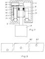
- the clutch roller carriage 2 is driven by a Drive belt 40 in the ceiling rail 4 near one The side wall of the same runs and the ends of which open up each wind a drive drum 42, 42 ', both of them are drivable in the sense of pulling the tape.
- a driving clutch 45 which is attached to the boom 30 and which from the drive belt 40 is traversed to at a particular Place of its extension to cooperate with him.
- the drive clutch 45 illustrated in FIGS. 3 and 4 consists of a housing 47 with an attached to this Cover 49, one between the two for passage of the drive belt 40 sufficient gap remains.
- an adjusting screw 51 here a grub screw, pressurized compression spring 53, the front Presses end on a locking ball 55. This in turn will pressed towards the drive belt 40.
- Latching openings 57 are made in the drive belt Distance from each other somewhat larger in the longitudinal direction of the tape is as the width of a wall element 1. In the direction of The width of the drive belt has a different locking opening Position.
- the channels of the locking balls are also located 55 of the driving clutches of the clutch roller carriages different heights, so that the locking ball of a wall element only at a discrete point on the drive belt 40 can fall into the locking opening 57 belonging to it and can establish a positive connection.
- the latch opening 57 is of sufficient size that the Locking ball 55 reaches the cover 49 when falling. On this way the depth of incidence is defined by namely the thickness of the drive belt 40 corresponds.
- the holding force generated by the locked ball is then still dependent on the spring loading and by means of the grub screw 51 adjustable. You overcome this Force, the wall element can be easily moved be, for example, if the tape drive fails. Disengaging also takes place when the wall element reaches its end position and stops while the drive belt continues to run.
- a second embodiment of the clutch 45 is in 6 to 9 are shown.
- the boom 30 arranged driving clutch 45 from one between two Bearing plates 61 about a vertical pivot axis 63 pivoted pivot housing 65, in which in a Bore a locking pin 67 is guided, its rear end by a weak compression spring 69 is acted upon.
- a support plate 71 attached so that the drive belt 40 between it and pass through the front end of the pivot housing 65 can.
- a recess 73 is provided in the area of the drive belt facing Support plate 71 the depth of the incidence of the locking pin 67 in the locking opening 57 of the drive belt 40 defines.
- the pivot axis 63 lies approximately midway between the two Ends of the swivel housing 65. Its rear end is framed between the legs 77 of a helical leg spring 75 on a storage post 79 sits and their legs over stop post 81 reach for the swivel housing 65 and this in the in Fig. 8 Seek to hold the middle position.
- the advantage of this training is the cushioning the impact of the wall elements. That deals with certain Speed moving drive belt 40 must be during of the coupling process the roller carriage 2 with attached Accelerate wall element 1 to its speed, which requires the greater driving force, the shorter is the time available. In the first 3, 4, this can be problematic and it can happen that the acceleration on the drive belt speed is not successful, but the locking ball 55 disengages again and its locking opening 57 lets pass.
- the second considered here Education is more reliable in this regard.
- the swivel housing is in the uncoupled state 65 of the screw leg spring 75 in the snap-in middle position, thus held at right angles to the drive belt 40 and with relative movements between the drive belt and driving clutch slips the weakly pressed Locking pin 67 slightly over the drive belt, which is in front the support plate 71 passes. If the associated locking opening 57 arrives, engages the locking pin 67, like this is shown in Fig. 8. Then if the edge of the locking opening 57 the sunken front end of the bolt reached, this is taken from the belt, which is under simultaneous acceleration of the roller carriage to one certain deflection of the pivot housing 65 from the central position leads, but not the disengaged swivel position 9 reached.
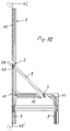
- Fig. 10 shows how a tension element 40 between its Drive drums 42, 42 'through a main line 7 and a subsequent parking area route 9 runs.
- a tension element 40 between its Drive drums 42, 42 'through a main line 7 and a subsequent parking area route 9 runs.
- the Parking area route 9 represents the straight-line extension the main route 7, of which at a junction 11 a branch section 15 via a curve 17 into the Parking area route 9 'merges.
- the wall element When considering the direction of movement when moving together the wall element is the leading roller carriage 3 the moving roller carriage without driving clutch and its guide rollers 28 run in the (in the considered Direction seen) left channel 26, which in the Branch section 15 merges.
- the trailing roller carriage 2 is the drivable clutch roller carriage with a Driving clutch 45 and its guide rollers 28 are in the (in the direction of travel) right channel 26, which continues into the parking area route 9.
- Fig. 14 is shown how a wall element when entering the Parking area rotates by 90 °.
- An auxiliary drive can be dispensed with in a known manner, that the distance between the parking area routes 9, 9 'from each other is chosen slightly smaller than the distance between the roller carriages 2, 3 of a wall element from each other, so that this in the parking area at an angle to the parking area routes stay.
- Fig. 11 shows a rail arrangement in which the wall elements from the main line 7 without turning into one Enter the parking area between two parking area sections 8, 8 '.
- the leading one when moving the wall elements together Roller carriage 3 is the moving roller carriage and its guide rollers 28 are in the right channel 26 led, which continues straight in the branch 11.
- the trailing roller carriage 2 is the clutch roller carriage and its guide rollers 28 are in the left Channel led, which at the junction 11 in the Parking area route 8 branches. This course must drive belt 40 follow.
- a deflection wheel is next to this 59 stored, via which the drive belt 40th running.
- the circumferential surface of the deflection wheel lies in a short distance from the path of the clutch roller carriage 2 in order to let their driving clutches 45 pass.
- the deflection wheel happens, the drive belt 40 is lifted from the deflection wheel 49.
- the deflection wheel 49 ensures Course of the drive belt between two neighboring ones drivable roller carriage.
- 11 is also an auxiliary drive for the moving roller carriages 3 on the parking area route 8 'to provide or an inclined parking solution to make it dispensable.
Landscapes
- Power-Operated Mechanisms For Wings (AREA)
- Transmission Devices (AREA)
- Building Environments (AREA)
Applications Claiming Priority (2)
| Application Number | Priority Date | Filing Date | Title |
|---|---|---|---|
| DE19625256A DE19625256C2 (de) | 1996-06-25 | 1996-06-25 | Raumtrennwand aus antreibbaren Wandelementen |
| DE19625256 | 1996-06-25 |
Publications (2)
| Publication Number | Publication Date |
|---|---|
| EP0816618A1 true EP0816618A1 (fr) | 1998-01-07 |
| EP0816618B1 EP0816618B1 (fr) | 2000-09-13 |
Family
ID=7797868
Family Applications (1)
| Application Number | Title | Priority Date | Filing Date |
|---|---|---|---|
| EP97109251A Expired - Lifetime EP0816618B1 (fr) | 1996-06-25 | 1997-06-07 | Paroi de séparation constituée d'éléments pouvant être entraínés |
Country Status (3)
| Country | Link |
|---|---|
| EP (1) | EP0816618B1 (fr) |
| AT (1) | ATE196341T1 (fr) |
| DE (2) | DE19625256C2 (fr) |
Families Citing this family (1)
| Publication number | Priority date | Publication date | Assignee | Title |
|---|---|---|---|---|
| DE102007060375A1 (de) * | 2007-12-12 | 2009-06-18 | Wilfried Boldt | Schienengeführtes Mobilwandelement mit einem Wandkörper |
Citations (3)
| Publication number | Priority date | Publication date | Assignee | Title |
|---|---|---|---|---|
| US2843375A (en) * | 1955-11-16 | 1958-07-15 | Richards Wilcox Mfg Co | Combined sliding and side sealing door |
| AU533406B2 (en) * | 1980-01-18 | 1983-11-24 | Acordial A.G. & Co. | Wall made of movable parts |
| DE4026098C1 (en) * | 1990-08-17 | 1991-12-12 | Hueppe Form Sonnenschutz- Und Raumtrennsysteme Gmbh, 2900 Oldenburg, De | Room partition of displaceable wall elements - which have support bolts, each horizontally, slidably mounted w.r.t. another one |
Family Cites Families (1)
| Publication number | Priority date | Publication date | Assignee | Title |
|---|---|---|---|---|
| DE9204436U1 (de) * | 1992-04-01 | 1992-05-27 | Goldbeck GmbH, 6382 Friedrichsdorf | An einer Decke o.dgl. aufhängbare Raumtrennwand sowie Rollenwagen hierfür |
-
1996
- 1996-06-25 DE DE19625256A patent/DE19625256C2/de not_active Expired - Fee Related
-
1997
- 1997-06-07 AT AT97109251T patent/ATE196341T1/de not_active IP Right Cessation
- 1997-06-07 EP EP97109251A patent/EP0816618B1/fr not_active Expired - Lifetime
- 1997-06-07 DE DE59702338T patent/DE59702338D1/de not_active Expired - Lifetime
Patent Citations (3)
| Publication number | Priority date | Publication date | Assignee | Title |
|---|---|---|---|---|
| US2843375A (en) * | 1955-11-16 | 1958-07-15 | Richards Wilcox Mfg Co | Combined sliding and side sealing door |
| AU533406B2 (en) * | 1980-01-18 | 1983-11-24 | Acordial A.G. & Co. | Wall made of movable parts |
| DE4026098C1 (en) * | 1990-08-17 | 1991-12-12 | Hueppe Form Sonnenschutz- Und Raumtrennsysteme Gmbh, 2900 Oldenburg, De | Room partition of displaceable wall elements - which have support bolts, each horizontally, slidably mounted w.r.t. another one |
Also Published As
| Publication number | Publication date |
|---|---|
| ATE196341T1 (de) | 2000-09-15 |
| DE19625256C2 (de) | 2002-02-07 |
| DE59702338D1 (de) | 2000-10-19 |
| EP0816618B1 (fr) | 2000-09-13 |
| DE19625256A1 (de) | 1998-01-08 |
Similar Documents
| Publication | Publication Date | Title |
|---|---|---|
| EP0574851B1 (fr) | Paroi de séparation constituée d'éléments déplaçables | |
| DE4026098C1 (en) | Room partition of displaceable wall elements - which have support bolts, each horizontally, slidably mounted w.r.t. another one | |
| DE1271369B (de) | Vorrichtung zum Abstellen von Kraftfahrzeugen od. dgl. | |
| DE2117922C3 (de) | Lagereinrichtung | |
| DE2545907B2 (de) | Förderbahn mit an einer Schiene geführten Katze | |
| DE1104985B (de) | Rollplattenvorrichtung zum Schliessen von OEffnungen oben offener Raeume ortsfester oder beweglicher Anlagen in Fahrzeugen | |
| DE3100860A1 (de) | Aneinandergrenzende transportsysteme und dafuer verwendbares fuehrerloses fahrzeug | |
| DE2259273A1 (de) | Vorrichtung zum umsetzen von stueckgut aus einer rollenbahn | |
| DE3805114A1 (de) | Bucheinhaengemaschine | |
| DE3218253C2 (fr) | ||
| EP0816618B1 (fr) | Paroi de séparation constituée d'éléments pouvant être entraínés | |
| DE3713431C2 (fr) | ||
| DE69507133T2 (de) | Vorrichtung bei hängeförderern | |
| DD251328A5 (de) | Selbstfahrender wagen | |
| DE60309133T2 (de) | Vorrichtung zur anpassung des abstandes zwischen förderfingern an die länge des produktes | |
| DE3712522C2 (fr) | ||
| DE2652843C2 (de) | Arretierung für eine Zunge einer Weiche für eine Einschienenhängebahn | |
| DE4402350A1 (de) | Torantrieb für einen horizontal verschiebbaren Sektionaltorflügel | |
| DE19540177C2 (de) | Fördersystem | |
| DE1803966A1 (de) | Jalousie | |
| AT233779B (de) | Stapelhaus, insbesondere Aufzuggarage | |
| DE3151682A1 (de) | Vertikaljalousie mit einer tragschiene im hohlprofil | |
| DE3024955C2 (de) | Verschiebevorrichtung für Kraftfahrzeuge in einer Waschanlage mit einem angetriebenen Portal | |
| DE2735680C2 (de) | Verfahren und Vorrichtung zum Bergen einer ohne Sicherheitswinde in einem Flöz geneigter Lagerung eingesetzten und hier manöverierunfähig liegengebliebenen Gewinnungsmaschine | |
| DE2435825C3 (de) | Vorrichtung zur Begrenzung des Durchhanges von Laufkatzseilen |
Legal Events
| Date | Code | Title | Description |
|---|---|---|---|
| PUAI | Public reference made under article 153(3) epc to a published international application that has entered the european phase |
Free format text: ORIGINAL CODE: 0009012 |
|
| 17P | Request for examination filed |
Effective date: 19971029 |
|
| AK | Designated contracting states |
Kind code of ref document: A1 Designated state(s): AT BE CH DE DK ES FI FR GB GR IE IT LI LU MC NL PT SE |
|
| 17Q | First examination report despatched |
Effective date: 19980220 |
|
| AKX | Designation fees paid |
Free format text: AT BE CH DE DK ES FI FR GB GR IE IT LI LU MC NL PT SE |
|
| RBV | Designated contracting states (corrected) |
Designated state(s): AT BE CH DE DK ES FI FR GB GR IE IT LI LU MC NL PT SE |
|
| GRAG | Despatch of communication of intention to grant |
Free format text: ORIGINAL CODE: EPIDOS AGRA |
|
| GRAG | Despatch of communication of intention to grant |
Free format text: ORIGINAL CODE: EPIDOS AGRA |
|
| GRAH | Despatch of communication of intention to grant a patent |
Free format text: ORIGINAL CODE: EPIDOS IGRA |
|
| GRAH | Despatch of communication of intention to grant a patent |
Free format text: ORIGINAL CODE: EPIDOS IGRA |
|
| GRAA | (expected) grant |
Free format text: ORIGINAL CODE: 0009210 |
|
| AK | Designated contracting states |
Kind code of ref document: B1 Designated state(s): AT BE CH DE DK ES FI FR GB GR IE IT LI LU MC NL PT SE |
|
| PG25 | Lapsed in a contracting state [announced via postgrant information from national office to epo] |
Ref country code: NL Free format text: LAPSE BECAUSE OF FAILURE TO SUBMIT A TRANSLATION OF THE DESCRIPTION OR TO PAY THE FEE WITHIN THE PRESCRIBED TIME-LIMIT Effective date: 20000913 Ref country code: IT Free format text: LAPSE BECAUSE OF FAILURE TO SUBMIT A TRANSLATION OF THE DESCRIPTION OR TO PAY THE FEE WITHIN THE PRESCRIBED TIME-LIMIT;WARNING: LAPSES OF ITALIAN PATENTS WITH EFFECTIVE DATE BEFORE 2007 MAY HAVE OCCURRED AT ANY TIME BEFORE 2007. THE CORRECT EFFECTIVE DATE MAY BE DIFFERENT FROM THE ONE RECORDED. Effective date: 20000913 Ref country code: FI Free format text: LAPSE BECAUSE OF FAILURE TO SUBMIT A TRANSLATION OF THE DESCRIPTION OR TO PAY THE FEE WITHIN THE PRESCRIBED TIME-LIMIT Effective date: 20000913 Ref country code: ES Free format text: THE PATENT HAS BEEN ANNULLED BY A DECISION OF A NATIONAL AUTHORITY Effective date: 20000913 |
|
| REF | Corresponds to: |
Ref document number: 196341 Country of ref document: AT Date of ref document: 20000915 Kind code of ref document: T |
|
| REG | Reference to a national code |
Ref country code: CH Ref legal event code: EP |
|
| REF | Corresponds to: |
Ref document number: 59702338 Country of ref document: DE Date of ref document: 20001019 |
|
| REG | Reference to a national code |
Ref country code: IE Ref legal event code: FG4D Free format text: GERMAN |
|
| ET | Fr: translation filed | ||
| PG25 | Lapsed in a contracting state [announced via postgrant information from national office to epo] |
Ref country code: SE Free format text: LAPSE BECAUSE OF FAILURE TO SUBMIT A TRANSLATION OF THE DESCRIPTION OR TO PAY THE FEE WITHIN THE PRESCRIBED TIME-LIMIT Effective date: 20001213 Ref country code: PT Free format text: LAPSE BECAUSE OF FAILURE TO SUBMIT A TRANSLATION OF THE DESCRIPTION OR TO PAY THE FEE WITHIN THE PRESCRIBED TIME-LIMIT Effective date: 20001213 Ref country code: DK Free format text: LAPSE BECAUSE OF FAILURE TO SUBMIT A TRANSLATION OF THE DESCRIPTION OR TO PAY THE FEE WITHIN THE PRESCRIBED TIME-LIMIT Effective date: 20001213 |
|
| PG25 | Lapsed in a contracting state [announced via postgrant information from national office to epo] |
Ref country code: GR Free format text: LAPSE BECAUSE OF FAILURE TO SUBMIT A TRANSLATION OF THE DESCRIPTION OR TO PAY THE FEE WITHIN THE PRESCRIBED TIME-LIMIT Effective date: 20001215 |
|
| GBT | Gb: translation of ep patent filed (gb section 77(6)(a)/1977) |
Effective date: 20001211 |
|
| NLV1 | Nl: lapsed or annulled due to failure to fulfill the requirements of art. 29p and 29m of the patents act | ||
| PG25 | Lapsed in a contracting state [announced via postgrant information from national office to epo] |
Ref country code: IE Free format text: LAPSE BECAUSE OF NON-PAYMENT OF DUE FEES Effective date: 20010419 |
|
| PG25 | Lapsed in a contracting state [announced via postgrant information from national office to epo] |
Ref country code: LU Free format text: LAPSE BECAUSE OF NON-PAYMENT OF DUE FEES Effective date: 20010607 Ref country code: AT Free format text: LAPSE BECAUSE OF NON-PAYMENT OF DUE FEES Effective date: 20010607 |
|
| REG | Reference to a national code |
Ref country code: IE Ref legal event code: FD4D |
|
| PG25 | Lapsed in a contracting state [announced via postgrant information from national office to epo] |
Ref country code: MC Free format text: LAPSE BECAUSE OF NON-PAYMENT OF DUE FEES Effective date: 20010630 Ref country code: LI Free format text: LAPSE BECAUSE OF NON-PAYMENT OF DUE FEES Effective date: 20010630 Ref country code: CH Free format text: LAPSE BECAUSE OF NON-PAYMENT OF DUE FEES Effective date: 20010630 Ref country code: BE Free format text: LAPSE BECAUSE OF NON-PAYMENT OF DUE FEES Effective date: 20010630 |
|
| PLBE | No opposition filed within time limit |
Free format text: ORIGINAL CODE: 0009261 |
|
| STAA | Information on the status of an ep patent application or granted ep patent |
Free format text: STATUS: NO OPPOSITION FILED WITHIN TIME LIMIT |
|
| 26N | No opposition filed | ||
| BERE | Be: lapsed |
Owner name: GOLDBECK G.M.B.H. Effective date: 20010630 |
|
| REG | Reference to a national code |
Ref country code: GB Ref legal event code: IF02 |
|
| REG | Reference to a national code |
Ref country code: CH Ref legal event code: PL |
|
| PGFP | Annual fee paid to national office [announced via postgrant information from national office to epo] |
Ref country code: FR Payment date: 20060511 Year of fee payment: 10 |
|
| PGFP | Annual fee paid to national office [announced via postgrant information from national office to epo] |
Ref country code: GB Payment date: 20060524 Year of fee payment: 10 |
|
| GBPC | Gb: european patent ceased through non-payment of renewal fee |
Effective date: 20070607 |
|
| REG | Reference to a national code |
Ref country code: FR Ref legal event code: ST Effective date: 20080229 |
|
| PG25 | Lapsed in a contracting state [announced via postgrant information from national office to epo] |
Ref country code: GB Free format text: LAPSE BECAUSE OF NON-PAYMENT OF DUE FEES Effective date: 20070607 |
|
| PG25 | Lapsed in a contracting state [announced via postgrant information from national office to epo] |
Ref country code: FR Free format text: LAPSE BECAUSE OF NON-PAYMENT OF DUE FEES Effective date: 20070702 |
|
| REG | Reference to a national code |
Ref country code: DE Ref legal event code: R082 Ref document number: 59702338 Country of ref document: DE Representative=s name: MEHLER ACHLER PATENTANWAELTE PARTNERSCHAFT MBB, DE Ref country code: DE Ref legal event code: R082 Ref document number: 59702338 Country of ref document: DE Representative=s name: MEHLER ACHLER PATENTANWAELTE, DE |
|
| PGFP | Annual fee paid to national office [announced via postgrant information from national office to epo] |
Ref country code: DE Payment date: 20160629 Year of fee payment: 20 |
|
| REG | Reference to a national code |
Ref country code: DE Ref legal event code: R071 Ref document number: 59702338 Country of ref document: DE |