EP0816666A2 - Abgas-Rückführvorrichtung - Google Patents
Abgas-Rückführvorrichtung Download PDFInfo
- Publication number
- EP0816666A2 EP0816666A2 EP97110903A EP97110903A EP0816666A2 EP 0816666 A2 EP0816666 A2 EP 0816666A2 EP 97110903 A EP97110903 A EP 97110903A EP 97110903 A EP97110903 A EP 97110903A EP 0816666 A2 EP0816666 A2 EP 0816666A2
- Authority
- EP
- European Patent Office
- Prior art keywords
- intake manifold
- molded part
- exhaust pipe
- wall
- outer circumference
- Prior art date
- Legal status (The legal status is an assumption and is not a legal conclusion. Google has not performed a legal analysis and makes no representation as to the accuracy of the status listed.)
- Withdrawn
Links
Images

Classifications
-
- F—MECHANICAL ENGINEERING; LIGHTING; HEATING; WEAPONS; BLASTING
- F02—COMBUSTION ENGINES; HOT-GAS OR COMBUSTION-PRODUCT ENGINE PLANTS
- F02M—SUPPLYING COMBUSTION ENGINES IN GENERAL WITH COMBUSTIBLE MIXTURES OR CONSTITUENTS THEREOF
- F02M35/00—Combustion-air cleaners, air intakes, intake silencers, or induction systems specially adapted for, or arranged on, internal-combustion engines
- F02M35/10—Air intakes; Induction systems
- F02M35/10091—Air intakes; Induction systems characterised by details of intake ducts: shapes; connections; arrangements
- F02M35/10144—Connections of intake ducts to each other or to another device
-
- F—MECHANICAL ENGINEERING; LIGHTING; HEATING; WEAPONS; BLASTING
- F02—COMBUSTION ENGINES; HOT-GAS OR COMBUSTION-PRODUCT ENGINE PLANTS
- F02M—SUPPLYING COMBUSTION ENGINES IN GENERAL WITH COMBUSTIBLE MIXTURES OR CONSTITUENTS THEREOF
- F02M26/00—Engine-pertinent apparatus for adding exhaust gases to combustion-air, main fuel or fuel-air mixture, e.g. by exhaust gas recirculation [EGR] systems
- F02M26/11—Manufacture or assembly of EGR systems; Materials or coatings specially adapted for EGR systems
-
- F—MECHANICAL ENGINEERING; LIGHTING; HEATING; WEAPONS; BLASTING
- F02—COMBUSTION ENGINES; HOT-GAS OR COMBUSTION-PRODUCT ENGINE PLANTS
- F02M—SUPPLYING COMBUSTION ENGINES IN GENERAL WITH COMBUSTIBLE MIXTURES OR CONSTITUENTS THEREOF
- F02M26/00—Engine-pertinent apparatus for adding exhaust gases to combustion-air, main fuel or fuel-air mixture, e.g. by exhaust gas recirculation [EGR] systems
- F02M26/12—Engine-pertinent apparatus for adding exhaust gases to combustion-air, main fuel or fuel-air mixture, e.g. by exhaust gas recirculation [EGR] systems characterised by means for attaching parts of an EGR system to each other or to engine parts
-
- F—MECHANICAL ENGINEERING; LIGHTING; HEATING; WEAPONS; BLASTING
- F02—COMBUSTION ENGINES; HOT-GAS OR COMBUSTION-PRODUCT ENGINE PLANTS
- F02M—SUPPLYING COMBUSTION ENGINES IN GENERAL WITH COMBUSTIBLE MIXTURES OR CONSTITUENTS THEREOF
- F02M26/00—Engine-pertinent apparatus for adding exhaust gases to combustion-air, main fuel or fuel-air mixture, e.g. by exhaust gas recirculation [EGR] systems
- F02M26/13—Arrangement or layout of EGR passages, e.g. in relation to specific engine parts or for incorporation of accessories
- F02M26/17—Arrangement or layout of EGR passages, e.g. in relation to specific engine parts or for incorporation of accessories in relation to the intake system
- F02M26/18—Thermal insulation or heat protection
-
- F—MECHANICAL ENGINEERING; LIGHTING; HEATING; WEAPONS; BLASTING
- F02—COMBUSTION ENGINES; HOT-GAS OR COMBUSTION-PRODUCT ENGINE PLANTS
- F02M—SUPPLYING COMBUSTION ENGINES IN GENERAL WITH COMBUSTIBLE MIXTURES OR CONSTITUENTS THEREOF
- F02M35/00—Combustion-air cleaners, air intakes, intake silencers, or induction systems specially adapted for, or arranged on, internal-combustion engines
- F02M35/10—Air intakes; Induction systems
- F02M35/10209—Fluid connections to the air intake system; their arrangement of pipes, valves or the like
- F02M35/10222—Exhaust gas recirculation [EGR]; Positive crankcase ventilation [PCV]; Additional air admission, lubricant or fuel vapour admission
-
- F—MECHANICAL ENGINEERING; LIGHTING; HEATING; WEAPONS; BLASTING
- F02—COMBUSTION ENGINES; HOT-GAS OR COMBUSTION-PRODUCT ENGINE PLANTS
- F02M—SUPPLYING COMBUSTION ENGINES IN GENERAL WITH COMBUSTIBLE MIXTURES OR CONSTITUENTS THEREOF
- F02M35/00—Combustion-air cleaners, air intakes, intake silencers, or induction systems specially adapted for, or arranged on, internal-combustion engines
- F02M35/10—Air intakes; Induction systems
- F02M35/10314—Materials for intake systems
- F02M35/10321—Plastics; Composites; Rubbers
-
- F—MECHANICAL ENGINEERING; LIGHTING; HEATING; WEAPONS; BLASTING
- F01—MACHINES OR ENGINES IN GENERAL; ENGINE PLANTS IN GENERAL; STEAM ENGINES
- F01M—LUBRICATING OF MACHINES OR ENGINES IN GENERAL; LUBRICATING INTERNAL COMBUSTION ENGINES; CRANKCASE VENTILATING
- F01M13/00—Crankcase ventilating or breathing
- F01M13/0011—Breather valves
- F01M2013/0027—Breather valves with a de-icing or defrosting system
-
- F—MECHANICAL ENGINEERING; LIGHTING; HEATING; WEAPONS; BLASTING
- F01—MACHINES OR ENGINES IN GENERAL; ENGINE PLANTS IN GENERAL; STEAM ENGINES
- F01M—LUBRICATING OF MACHINES OR ENGINES IN GENERAL; LUBRICATING INTERNAL COMBUSTION ENGINES; CRANKCASE VENTILATING
- F01M13/00—Crankcase ventilating or breathing
- F01M13/04—Crankcase ventilating or breathing having means for purifying air before leaving crankcase, e.g. removing oil
- F01M2013/0455—Crankcase ventilating or breathing having means for purifying air before leaving crankcase, e.g. removing oil with a de-icing or defrosting system
-
- F—MECHANICAL ENGINEERING; LIGHTING; HEATING; WEAPONS; BLASTING
- F01—MACHINES OR ENGINES IN GENERAL; ENGINE PLANTS IN GENERAL; STEAM ENGINES
- F01M—LUBRICATING OF MACHINES OR ENGINES IN GENERAL; LUBRICATING INTERNAL COMBUSTION ENGINES; CRANKCASE VENTILATING
- F01M13/00—Crankcase ventilating or breathing
- F01M13/04—Crankcase ventilating or breathing having means for purifying air before leaving crankcase, e.g. removing oil
- F01M2013/0472—Crankcase ventilating or breathing having means for purifying air before leaving crankcase, e.g. removing oil using heating means
Definitions
- the invention relates to a device for controlled feedback of exhaust gases to the intake manifold of an internal combustion engine, with one in an opening of the intake manifold wall usable, metallic exhaust pipe for exhaust gas routing between an EGR valve (Exhaust Gas Recirculation Valve) and the intake manifold, which is in its opposite the intake manifold wall area to be sealed by a thermal barrier coating is included.
- EGR valve Exhaust Gas Recirculation Valve
- Exhaust gas recirculation takes place at the current state of the art only during certain engine operating conditions, i.e. H. the EGR valve is often closed.
- the EGR valve is often closed.
- Exhaust gas can be returned to the engine intake side, even if the amount of exhaust gas returned is regulated depending on the load.
- the intake manifold was a light metal casting; for cost reasons and to save weight are used as intake manifolds in modern engines however, injection molded plastic parts used.
- a metallic exhaust pipe leads from the EGR valve to the intake manifold and protrudes into an opening of the intake manifold wall into it, this opening being larger than the outside diameter of the exhaust pipe, so that the latter the intake manifold wall not touched. Because the recirculated exhaust gases in the area temperatures of the exhaust pipe leading away from the EGR valve from 350 to 400 ° C, compared to which the plastic of Intake manifold is not stable, takes place at the state of the Technique to fix the exhaust pipe leading away from the EGR valve in the intake manifold and its seal against the Intake manifold as follows: is on the metallic exhaust pipe a metallic sleeve is welded to the tube at a distance surrounds, so that between the latter and the sleeve annular air gap, which gives the thermal insulation serves; so that the metallic sleeve is welded to the exhaust pipe it has on the EGR valve End a cone-shaped area with its small Diameter bears against the outer circumference of the exhaust pipe and is welded there while the intake manifold
- the intake manifold now has one said opening in the short, surrounding the intake manifold wall Pipe socket-shaped approach in which the metallic sleeve is inserted together with the exhaust pipe and against its inner wall the outer circumference of the sleeve by means of an O-ring is sealed.
- a similar exhaust gas recirculation device results from the EP-A-0 647 779; in this device is on the exhaust gas recirculation serving metallic exhaust pipe also a attached approximately conical metal sleeve, namely e.g. B. by soldering, the attachment point not the EGR valve, but facing the plastic intake manifold is.
- the seal is not made using a O-ring, but by means of a flexible plastic sleeve, which on the one hand on the intake manifold and on the other hand with her, facing away from the latter, the metallic one End region comprising sleeve is fixed to this sleeve, namely on the sleeve area with the largest diameter by means of a clamping ring.
- the invention was therefore based on the object of an exhaust gas recirculation device of the kind mentioned at the beginning, which is then combined with a plastic intake manifold when the EGR valve is in constant operation, and which enables long service life and low manufacturing costs.
- the basic idea of the present invention is that at least that area of the metallic exhaust pipe which adjacent after installing the intake manifold wall is a shielding thermal insulation layer made of an easy to process high temperature resistant and good thermal insulation properties having to form, curable molding compound, which also as good as possible on the metallic exhaust pipe is liable, whereby, as will become clear from the following, such liability easily by other fastening and Sealing measures can be replaced.
- a particularly suitable molding compound results from the in Form of the International published WO 95/26938 Patent application PCT / EP95 / 00561 by Elring Klinger GmbH, which is why it is proposed according to the present invention to design a device of the type mentioned in the introduction, that the thermal barrier coating is made from a curable, a high temperature resistant binder, particles of a porous Materials as well as a fibrous or needle-shaped reinforcement component containing molding compound produced, sleeve-shaped molded part is formed, which one hand gas-tight in the area of the opening of the intake manifold wall the latter definable and on the other hand with at least one axial portion of its inner wall surface against the outer circumference abuts the exhaust pipe, so as to the exhaust pipe with respect of the intake manifold and the molded part with respect to the exhaust pipe to position.
- a molded part produced from such a molding compound is not only particularly temperature-resistant and heat-insulating, but it also has what is necessary for engine operation mechanical fatigue strength, so that even in engine operation constantly occurring vibrations do not cause cracks or permanent breaks to lead.
- the inner wall surface of the molded part and the outer circumference of the exhaust pipe along one around the latter running line or in three on this Points lying against each other would line up to the Position the molded part on the metallic exhaust pipe or in the If the molded part is fixed on the intake manifold and / or the metallic exhaust pipe on the EGR valve with respect to the intake manifold to be determined. However, if the molding as one over their entire length against the outer circumference of the exhaust pipe adjacent sleeve is formed, the molded part in Form from the molding compound on the metallic exhaust pipe and harden, with the appropriate choice of the in the molding compound contained binder also a permanent connection can be achieved between molded part and exhaust pipe.
- the gas pipe provided with the molded part gas-tight It is recommended to insert it into the intake manifold for sealing an annular, opposite the intake manifold wall with radial pressure against the outer circumference of the sleeve Seal made of elastic material, which then another thermal insulation element at the transition to the plastic wall of the intake manifold.
- the molded part to be provided according to the invention but also the air gap thermal insulation realize the known device described at the outset, by designing the molded part so that it is only in its valve-side end area with its inner wall surface bears against the outer circumference of the exhaust pipe and otherwise runs at a radial distance from this outer circumference, so that between the inner wall surface of the molded part and the outer circumference of the exhaust pipe gives an annular space, which with air, exhaust gas or a mixture of these and an additional one Thermal insulation effect.
- the molding with the exhaust pipe firmly and connect permanently.
- the molded part with its valve-side end face in the axial direction against one with respect supports the solid end face of the exhaust pipe.
- the molded part can also be particularly easy in the direction fixed to the intake manifold transversely to the exhaust pipe axis, by pulling the molded part away from the EGR valve End area with a graduated outer diameter, so that it has an axial section of smaller diameter inserted into the opening of the intake manifold wall can be.
- the molded part is one after a device or more of claims 2 to 16 in the form of International patent application published in WO 95/26938 PCT / EP95 / 00561.
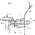
- FIG. 1 shows an EGR valve 10 in a side view, from which a metallic exhaust pipe serving for exhaust gas recirculation 12 to an intake manifold designated as a whole by 14 leads. Only the area of the latter became a manifold wall 16 shown, in which the latter a Opening 18 for the entry of the exhaust pipe 12 into the interior of the intake manifold 14.
- a cuff 20 On the end region of the exhaust pipe facing the EGR valve 10 12 is a cuff 20 attached, which a 1 right end face 20a, which is vertical runs to the axis 12a of the exhaust pipe 12 and, as is the following will result, a stop and sealing surface forms. It is preferably the cuff 20 around a part made of a material which is at least approximately the same coefficient of thermal expansion how the metal of the exhaust pipe 12 has; in addition, the Sleeve 20 gas-tight on the outer peripheral surface of the exhaust pipe 12 sit.
- end face 20a could also have a circumferential one Shoulder, a collar of the metallic exhaust pipe 12 or an end face of the EGR valve 10 is formed.
- a sleeve-shaped molded part 24 which consists of a molding compound was produced as in the publication WO 95/26938 has been described and claimed.
- the molding 24 is rotationally symmetrical to the axis 12a according to the invention 1 and has an approximately conical shape on the left axial section, to the right a whole roughly circular cylindrical section connects so that a gas-filled between the exhaust pipe 12 and the molded part 24 Annulus 26 results.
- the smallest inside diameter of the molded part 24 the same or only very slightly larger than the outside diameter of the exhaust pipe 12 (At least on that surrounded by the left end region of the molded part 24 Body), so that the molded part 24 when pushed on the exhaust pipe 12 is centered on the latter.
- the molded part 24 a graded one at its right end according to the drawing figures Outside diameter and thus forms a perpendicular to End surface 30 extending along axis 12a and a shoulder 32 with a smaller outside diameter.
- the latter is now in accordance with the invention the same or slightly smaller than that Diameter of the opening 18 in the manifold wall 16 so that the molded part 24 with the projection 32 also with respect to the opening 18 of the intake manifold 14 can be centered.
- End face 34 of the molded part 24 is located in each case an annular groove 36 and 38, in each of which a not shown O-ring can be inserted so that the joint between the Intake manifold wall 16 and the molded part 24 or between the Seal cuff 20 and the molded part 24 when the invention Device is mounted on the intake manifold 14 -
- the molded part 24 is in the axial direction between the Cuff 20 and the intake manifold wall 16 clamped.
- Fig. 3 were the first embodiment corresponding Parts with the same reference numerals as in Figures 1 and 2 provided, but with the addition of an A.
- the plastic wall 16A of the intake manifold around its opening 18A a tubular socket Approach 50A through which the metallic exhaust pipe 12A a heat-insulating surrounding the exhaust pipe Form part 24A protrudes.
- the molded part 24A is firmly connected to the exhaust pipe 12A, what z. B. can be achieved in that the molded part 24A is formed in situ on the exhaust pipe 12A.
- it may recommend the exhaust pipe 12A on his To provide outer circumference with an annular groove 52A, so that the Molding compound enters this ring groove when the molded part 24A in is formed in situ on the exhaust pipe 12A.
- the intake manifold wall 16A centered and kept gas-tight is between the neck 50A of the manifold wall 16A and an annular seal on the outer periphery of the molded part 24A 60A made of an elastic and temperature-resistant material arranged, which is annular and an approximately L-shaped Cross section has and is dimensioned so that it with radial Pressing is held on the one hand on the molded part 24A and on the other hand abuts against the inner wall surface of the projection 50A.
- the exhaust pipe is 12 or 12A in the axial direction Preferably so dimensioned that it protrudes a bit into the interior of the intake manifold, d. H. protrudes over the manifold wall 16 or 16A.
Landscapes
- Engineering & Computer Science (AREA)
- Chemical & Material Sciences (AREA)
- Combustion & Propulsion (AREA)
- Mechanical Engineering (AREA)
- General Engineering & Computer Science (AREA)
- Manufacturing & Machinery (AREA)
- Exhaust-Gas Circulating Devices (AREA)
- Exhaust Silencers (AREA)
Abstract
Vorrichtung zur gesteuerten Rückführung von Abgasen zum Ansaugkrümmer
eines Verbrennungsmotors, mit einem in eine Öffnung
der aus einem Kunststoff bestehenden Ansaugkrümmerwandung
einsetzbaren, metallischen Abgasrohr zur Abgasführung
zwischen einem EGR-Ventil und dem Ansaugkrümmer, welches in
seinem gegenüber der Ansaugkrümmerwandung abzudichtenden Bereich
von einer Wärmedämmschicht umfaßt wird; zur Verhinderung
einer Überhitzung der Ansaugkrümmerwandung wird die
Wärmedämmschicht von einem aus einer aushärtbaren Formmasse
hergestellten, hülsenförmigen Formteil hoher Temperaturbeständigkeit
und guter Wärmeisoliereigenschaften gebildet,
welches einerseits gasdicht in der Öffnung der Ansaugkrümmerwandung
festlegbar und andererseits mit mindestens einem
axialen Abschnitt seiner Innenwandfläche gegen den Außenumfang
des Abgasrohres anliegt.
Description
Die Erfindung betrifft eine Vorrichtung zur gesteuerten Rückführung
von Abgasen zum Ansaugkrümmer eines Verbrennungsmotors,
mit einem in eine Öffnung der Ansaugkrümmerwandung
einsetzbaren, metallischen Abgasrohr zur Abgasführung zwischen
einem EGR-Ventil (Exhaust Gas Recirculation Ventil) und
dem Ansaugkrümmer, welches in seinem gegenüber der Ansaugkrümmerwandung
abzudichtenden Bereich von einer Wärmedämmschicht
umfaßt wird.
Bei modernen Otto- und Dieselmotoren wird ein Teil der Abgase
der Ansaugseite des Motors zugeführt, um im Abgas enthaltene
unverbrannte Kohlenwasserstoffe und gegebenenfalls auch Rußpartikel
zu verbrennen. Die zur Ansaugseite des Motors zurückgeführte
Abgasmenge wird mit Hilfe eines sogenannten
EGR-Ventils lastabhängig geregelt.
Beim heutigen Stand der Technik erfolgt eine Abgasrückführung
nur während gewisser Betriebszustände des Motors, d. h. das
EGR-Ventil ist häufig geschlossen. Um jedoch die ab 1998
geltenden strengeren Abgasnormen zu erfüllen, muß das
EGR-Ventil ständig in Betrieb sein, d. h. es muß ständig
Abgas zur Motor-Ansaugseite zurückgeführt werden, auch wenn
die zurückgeführte Abgasmenge lastabhängig geregelt wird.
Bis vor einiger Zeit handelte es sich beim Ansaugkrümmer um
ein Leichtmetall-Gußteil; aus Kostengründen sowie zur Gewichtseinsparung
werden bei modernen Motoren als Ansaugkrümmer
jedoch im Spritzgußverfahren hergestellte Kunststoff-Formteile
verwendet.
Vom EGR-Ventil führt ein metallisches Abgasrohr zum Ansaugkrümmer
und ragt in eine Öffnung der Ansaugkrümmerwandung
hinein, wobei diese Öffnung größer ist als der Außendurchmesser
des Abgasrohres, so daß letzteres die Ansaugkrümmerwandung
nicht berührt. Da die rückgeführten Abgase im Bereich
des vom EGR-Ventil wegführenden Abgasrohres noch Temperaturen
von 350 bis 400°C haben, gegenüber welchen der Kunststoff des
Ansaugkrümmers nicht beständig ist, erfolgt beim Stand der
Technik die Fixierung des vom EGR-Ventil wegführenden Abgasrohres
im Ansaugkrümmer sowie seine Abdichtung gegenüber dem
Ansaugkrümmer wie folgt: An dem metallischen Abgasrohr ist
eine metallische Hülse angeschweißt, die das Rohr mit Abstand
umgibt, so daß sich zwischen dem letzteren und der Hülse ein
ringförmiger Luftspalt ergibt, welcher der Wärmeisolierung
dient; damit die metallische Hülse am Abgasrohr angeschweißt
werden kann, besitzt sie an ihrem dem EGR-Ventil zugewandten
Ende einen konusförmigen Bereich, der mit seinem kleinen
Durchmesser gegen den Außenumfang des Abgasrohres anliegt und
dort angeschweißt ist, während das Ansaugkrümmer-seitige Ende
der Hülse offen ist. Der Ansaugkrümmer besitzt nun einen die
genannte Öffnung in der Ansaugkrümmerwandung umgebenden, kurzen,
rohrstutzenförmigen Ansatz, in den die metallische Hülse
samt Abgasrohr eingesteckt wird und gegenüber dessen Innenwandung
der Außenumfang der Hülse mittels eines O-Ringes
abgedichtet ist.
Eine ähnliche Abgas-Rückführvorrichtung ergibt sich aus der
EP-A-0 647 779; bei dieser Vorrichtung ist an dem der Abgasrückführung
dienenden metallischen Abgasrohr gleichfalls eine
ungefähr konusförmige metallische Hülse befestigt, und zwar
z. B. durch Löten, wobei die Befestigungsstelle nicht dem
EGR-Ventil, sondern dem Kunststoff-Ansaugkrümmer zugekehrt
ist. Außerdem erfolgt die Abdichtung nicht mittels eines
O-Ringes, sondern mittels einer flexiblen Kunststoff-Manschette,
welche einerseits am Ansaugkrümmer und andererseits
mit ihrem vom letzteren abgewandten, die metallische
Hülse umfassenden Endbereich an dieser Hülse festgelegt ist,
und zwar an dem den größten Durchmesser aufweisenden Hülsenbereich
mittels eines Spannringes.
Diese Art der Einführung des metallischen Abgasrohres in
einen Kunststoff-Ansaugkrümmer reicht aus, wenn die Abgasrückführung
nur kurzzeitig erfolgt, sie ist jedoch ungeeignet,
wenn ständig Abgas zur Ansaugseite des Motors zurückgeführt
wird, weil dann die der metallischen Hülse benachbarten
Bereiche des aus Kunststoff bestehenden Ansaugkrümmers zu
heiß werden würden.
Der Erfindung lag deshalb die Aufgabe zugrunde, eine Abgas-Rückführvorrichtung
der eingangs erwähnten Art zu schaffen,
die auch dann mit einem Kunststoff-Ansaugkrümmer kombiniert
werden kann, wenn das EGR-Ventil ständig in Betrieb ist, und
die hohe Standzeiten und geringe Herstellungskosten ermöglicht.
Grundgedanke der vorliegenden Erfindung ist es, die mindestens
denjenigen Bereich des metallischen Abgasrohres, welcher
nach der Montage der Ansaugkrümmerwandung benachbart
ist, abschirmende Wärmedämmschicht aus einer einfach zu verarbeitenden,
hoch temperaturbeständigen und gute Wärmedämmeigenschaften
aufweisenden, aushärtbaren Formmasse zu bilden,
welche möglichst auch noch gut an dem metallischen Abgasrohr
haftet, wobei, wie sich aus dem Folgenden noch ergeben wird,
eine solche Haftung ohne weiteres durch andere Befestigungs- und
Abdichtmaßnahmen ersetzt werden kann.
Eine besonders geeignete Formmasse ergibt sich aus der in
Form der WO 95/26938 veröffentlichten Internationalen
Patentanmeldung PCT/EP95/00561 der Firma Elring Klinger GmbH,
weshalb gemäß der vorliegenden Erfindung vorgeschlagen wird,
eine Vorrichtung der eingangs erwähnten Art so zu gestalten,
daß die Wärmedämmschicht von einem aus einer aushärtbaren,
ein hochtemperaturfestes Bindemittel, Partikel eines porenhaltigen
Materials sowie eine faser- oder nadelförmige Verstärkungskomponente
enthaltenden Formmasse hergestellten,
hülsenförmigen Formteil gebildet wird, welches einerseits
gasdicht im Bereich der Öffnung der Ansaugkrümmerwandung an
letzterer festlegbar und andererseits mit mindestens einem
axialen Abschnitt seiner Innenwandfläche gegen den Außenumfang
des Abgasrohres anliegt, um so das Abgasrohr bezüglich
des Ansaugkrümmers sowie das Formteil bezüglich des Abgasrohres
zu positionieren.
Ein aus einer solchen Formmasse hergestelltes Formteil ist
nicht nur besonders temperaturbeständig und wärmeisolierend,
sondern es hat auch die für den Motorbetrieb erforderliche
mechanische Dauerfestigkeit, so daß auch die im Motorbetrieb
ständig auftretenden Vibrationen nicht zu Rissen oder Dauerbrüchen
führen.
Grundsätzlich würde es ausreichen, wenn die Innenwandfläche
des Formteils und der Außenumfang des Abgasrohres längs einer
um das letztere herumlaufenden Linie oder in drei auf dieser
Linie liegenden Punkten gegeneinander anliegen würden, um das
Formteil am metallischen Abgasrohr zu positionieren oder im
Falle der Festlegung des Formteils am Ansaugkrümmer und/oder
am EGR-Ventil das metallische Abgasrohr bezüglich des Ansaugkrümmers
festzulegen. Wenn hingegen das Formteil als eine
über ihre ganze Länge gegen den Außenumfang des Abgasrohres
anliegende Hülse ausgebildet ist, läßt sich das Formteil in
situ auf dem metallischen Abgasrohr aus der Formmasse formen
und aushärten, wobei bei entsprechender Wahl des in der Formmasse
enthaltenen Bindemittels auch eine dauerhafte Verbindung
zwischen Formteil und Abgasrohr erzielt werden kann.
Um bei einer solchen Ausführungsform der erfindungsgemäßen
Vorrichtung das mit dem Formteil versehene Abgasrohr gasdicht
in den Ansaugkrümmer einzuführen, empfiehlt es sich, zur Abdichtung
gegenüber der Ansaugkrümmerwandung eine ringförmige,
mit radialer Pressung gegen den Außenumfang der Hülse anliegende
Dichtung aus elastischem Material vorzusehen, welche
dann auch noch ein weiteres Wärmedämmelement am Übergang zu
der Kunststoffwandung des Ansaugkrümmers bildet.
Mit Hilfe des erfindungsgemäß vorzusehenden Formteils läßt
sich aber auch zusätzlich die Luftspalt-Wärmedämmung der
eingangs beschriebenen bekannten Vorrichtung verwirklichen,
indem das Formteil so gestaltet wird, daß es lediglich in
seinem ventilseitigen Endbereich mit seiner Innenwandfläche
gegen den Außenumfang des Abgasrohres anliegt und im übrigen
mit radialem Abstand von diesem Außenumfang verläuft, so daß
sich zwischen Innenwandfläche des Formteils und Außenumfang
des Abgasrohres ein Ringraum ergibt, welcher mit Luft, Abgas
oder einem Gemisch hieraus gefüllt ist und einen zusätzlichen
Wärmedämmeffekt mit sich bringt.
Bei der erfindungsgemäßen Lösung kann aber auch völlig darauf
verzichtet werden, das Formteil mit dem Abgasrohr fest und
dauerhaft zu verbinden. Bei Konstruktionen ohne eine solche
Verbindung erfolgt die Fixierung des Formteils zweckmäßigerweise
unter anderem dadurch, daß sich das Formteil mit seiner
ventilseitigen Stirnfläche in axialer Richtung gegen eine bezüglich
des Abgasrohres feste Stirnfläche abstützt. Auf der
anderen Seite wird man das Formteil so gestalten, daß es (an
seinem vom EGR-Ventil abgewandten Endbereich) eine Stirnfläche
besitzt, welche sich insbesondere über einen Dichtring
an der Ansaugkrümmerwandung abstützt. In einem solchen Fall
kann das Formteil auch noch besonders einfach in Richtung
quer zur Abgasrohrachse am Ansaugkrümmer festgelegt werden,
indem man das Formteil an seinem vom EGR-Ventil abgewandten
Endbereich mit einem abgestuften Außendurchmesser versieht,
so daß es mit einem axialen Abschnitt kleineren Durchmessers
in die Öffnung der Ansaugkrümmerwandung passend eingesetzt
werden kann.
Bei besonders vorteilhaften Ausführungsformen der erfindungsgemäßen
Vorrichtung ist das Formteil ein solches nach einem
oder mehreren der Ansprüche 2 bis 16 der in Form der
WO 95/26938 veröffentlichten Internationalen Patentanmeldung
PCT/EP95/00561.
Weitere Merkmale, Vorteile und Einzelheiten der Erfindung ergeben
sich aus den beigefügten Ansprüchen und/oder aus der
beigefügten zeichnerischen Darstellung sowie der nachfolgenden
Beschreibung zweier besonders vorteilhafter Ausführungsformen
der erfindungsgemäßen Abgasrückführvorrichtung; in der
Zeichnung zeigen:
- Fig. 1
- einen Längsschnitt durch eine erste Ausführungsform, wobei in Fig. 1 links auch noch das EGR-Ventil in Seitenansicht und rechts ein Teil der Ansaugkrümmerwandung im Schnitt dargestellt wurden;
- Fig. 2
- einen Ausschnitt aus Fig. 1, nämlich das der Wärmedämmung dienende Formteil wiederum im Längsschnitt, jedoch in größerem Maßstab als in Fig. 1, und
- Fig. 3
- eine der Fig. 1 entsprechende Darstellung einer zweiten Ausführungsform, jedoch ohne EGR-Ventil.
Die Fig. 1 zeigt ein EGR-Ventil 10 in einer Seitenansicht,
von dem ein der Abgasrückführung dienendes metallisches Abgasrohr
12 zu einem als Ganzes mit 14 bezeichneten Ansaugkrümmer
führt. Von dem letzteren wurde nur derjenige Bereich
einer Krümmerwandung 16 dargestellt, in dem die letztere eine
Öffnung 18 für den Eintritt des Abgasrohres 12 in das Innere
des Ansaugkrümmers 14 aufweist.
Auf dem dem EGR-Ventil 10 zugewandten Endbereich des Abgasrohrs
12 ist eine Manschette 20 fest angebracht, welche eine
gemäß Fig. 1 rechte Stirnfläche 20a besitzt, die senkrecht
zur Achse 12a des Abgasrohrs 12 verläuft und, wie sich aus
dem Folgenden noch ergeben wird, eine Anschlag- und Abdichtfläche
bildet. Vorzugsweise handelt es sich bei der Manschette
20 um ein Teil aus einem Werkstoff, welcher mindestens
ungefähr den gleichen Temperaturausdehnungskoeffizienten
wie das Metall des Abgasrohrs 12 hat; außerdem sollte die
Manschette 20 gasdicht auf der Außenumfangsfläche des Abgasrohrs
12 sitzen.
Die Stirnfläche 20a könnte aber auch durch eine umlaufende
Schulter, einen Ringbund des metallischen Abgasrohres 12 oder
eine Stirnfläche des EGR-Ventils 10 gebildet werden.
Zwischen der Stirnfläche 20a und der Krümmerwandung 16 verläuft
ein hülsenförmiges Formteil 24, welches aus einer Formmasse
hergestellt wurde, wie sie in der Druckschrift
WO 95/26938 beschrieben und beansprucht wurde. Das Formteil
24 ist erfindungsgemäß rotationssymmetrisch zur Achse 12a
ausgebildet und hat gemäß Fig. 1 links einen ungefähr konischen
axialen Abschnitt, an den sich nach rechts ein ganz
grob kreiszylindrischer Abschnitt anschließt, so daß sich
zwischen dem Abgasrohr 12 und dem Formteil 24 ein gasgefüllter
Ringraum 26 ergibt. Erfindungsgemäß ist der kleinste Innendurchmesser
des Formteils 24 gleich oder nur ganz geringfügig
größer als der Außendurchmesser des Abgasrohres 12
(zumindest an der vom linken Endbereich des Formteils 24 umgebenen
Stelle), so daß das Formteil 24 beim Aufschieben auf
das Abgasrohr 12 auf letzterem zentriert wird.
Wie die Figuren 1 und 2 erkennen lassen, hat das Formteil 24
an seinem gemäß den Zeichnungsfiguren rechten Ende einen abgestuften
Außendurchmesser und bildet so eine senkrecht zur
Achse 12a verlaufende Stirnfläche 30 sowie einen Ansatz 32
mit kleinerem Außendurchmesser. Der letztere ist nun erfindungsgemäß
gleich oder ganz geringfügig kleiner wie der
Durchmesser der Öffnung 18 in der Krümmerwandung 16, so daß
das Formteil 24 mit dem Ansatz 32 auch bezüglich der Öffnung
18 des Ansaugkrümmers 14 zentriert werden kann.
In der Stirnfläche 30 und einer der letzteren gegenüberliegenden
Stirnfläche 34 des Formteils 24 befindet sich jeweils
eine Ringnut 36 bzw. 38, in die jeweils ein nicht dargestellter
O-Ring eingelegt werden kann, um so die Fuge zwischen der
Ansaugkrümmerwandung 16 und dem Formteil 24 bzw. zwischen der
Manschette 20 und dem Formteil 24 abzudichten, wenn die erfindungsgemäße
Vorrichtung am Ansaugkrümmer 14 montiert wird
- dabei wird das Formteil 24 in axialer Richtung zwischen der
Manschette 20 und der Ansaugkrümmerwandung 16 eingespannt.
In Fig. 3 wurden der ersten Ausführungsform entsprechende
Teile mit denselben Bezugszeichen wie in den Figuren 1 und 2
versehen, jedoch unter Hinzufügung eines A.
Bei der in Fig. 3 dargestellten zweiten Ausführungsform besitzt
die aus Kunststoff bestehende Wandung 16A des Ansaugkrümmers
um ihre Öffnung 18A herum einen rohrstutzenförmigen
Ansatz 50A, durch den das metallische Abgasrohr 12A samt
einem das Abgasrohr mantelartig umgebenden, wärmedämmenden
Formteil 24A hindurchragt. Bei dieser zweiten Ausführungsform
ist das Formteil 24A fest mit dem Abgasrohr 12A verbunden,
was z. B. dadurch erreicht werden kann, daß das Formteil 24A
in situ auf dem Abgasrohr 12A gebildet wird. Wie in Fig. 3
angedeutet, kann es sich empfehlen, das Abgasrohr 12A an seinem
Außenumfang mit einer Ringnut 52A zu versehen, so daß die
Formmasse in diese Ringnut eintritt, wenn das Formteil 24A in
situ auf dem Abgasrohr 12A gebildet wird. Des weiteren bildet
ein Ringbund 54A des Abgasrohrs 12A eine axiale Anschlag- und
Abdichtfläche für das Formteil 24A.
Damit das Abgasrohr 12A samt Formteil 24A in der Öffnung 18A
der Ansaugkrümmerwandung 16A zentriert und gasdicht gehalten
wird, ist zwischen dem Ansatz 50A der Krümmerwandung 16A und
dem Außenumfang des Formteils 24A eine ringförmige Dichtung
60A aus einem elastischen und temperaturbeständigen Material
angeordnet, die ringförmig ist und einen ungefähr L-förmigen
Querschnitt hat sowie so bemessen ist, daß sie mit radialer
Pressung einerseits auf dem Formteil 24A gehalten wird und
andererseits gegen die Innenwandfläche des Ansatzes 50A anliegt.
Wie die Figuren 1 und 3 erkennen lassen, ist das Abgasrohr 12
bzw. 12A in axialer Richtung Vorzugsweise so bemessen, daß es
ein Stück weit in das Innere des Ansaugkrümmers hineinragt,
d. h. über die Krümmerwandung 16 bzw. 16A übersteht.
Claims (10)
- Vorrichtung zur gesteuerten Rückführung von Abgasen zum Ansaugkrümmer eines Verbrennungsmotors, mit einem in eine Öffnung der aus einem Kunststoff bestehenden Ansaugkrümmerwandung einsetzbaren, metallischen Abgasrohr zur Abgasführung zwischen einem EGR-Ventil und dem Ansaugkrümmer, welches in seinem gegenüber der Ansaugkrümmerwandung abzudichtenden Bereich von einer Wärmedämmschicht umfaßt wird, dadurch gekennzeichnet, daß die Wärmedämmschicht von einem aus einer aushärtbaren, ein hochtemperaturfestes Bindemittel, Partikel eines porenhaltigen Materials sowie eine faser- oder nadelförmige Verstärkungskomponente enthaltenden Formmasse hergestellten, hülsenförmigen Formteil (24; 24A) gebildet wird, welches einerseits in der Öffnung (18; 18A) der Ansaugkrümmerwandung (16; 16A) sowie gegenüber letzterer abgedichtet festlegbar und andererseits mit mindestens einem axialen Abschnitt seiner Innenwandfläche gegen den Außenumfang des Abgasrohres (12; 12A) anliegt.
- Vorrichtung nach Anspruch 1, dadurch gekennzeichnet, daß das Formteil (24A) als eine über ihre ganze Länge gegen den Außenumfang des Abgasrohres (12A) anliegende Hülse ausgebildet ist.
- Vorrichtung nach Anspruch 2, dadurch gekennzeichnet, daß zur Abdichtung gegenüber der Ansaugkrümmerwandung (16A) eine ringförmige, mit radialer Pressung gegen den Außenumfang der Hülse (24A) anliegende Dichtung (60A) vorgesehen ist.
- Vorrichtung nach Anspruch 1, dadurch gekennzeichnet, daß das Formteil (24) lediglich in seinem ventilseitigen Endbereich mit seiner Innenwandfläche gegen den Außenumfang des Abgasrohres (12) anliegt und im übrigen mit radialem Abstand von diesem Außenumfang verläuft.
- Vorrichtung nach einem oder mehreren der vorstehenden Ansprüche, dadurch gekennzeichnet, daß sich das Formteil (24; 24A) mit seiner ventilseitigen Stirnfläche in axialer Richtung gegen eine bezüglich des Abgasrohres (12; 12A) feste Stirnfläche (20a; 54A) abstützt.
- Vorrichtung nach Anspruch 5, gekennzeichnet durch einen zwischen den beiden Stirnflächen angeordneten Dichtring.
- Vorrichtung nach einem oder mehreren der vorstehenden Ansprüche, dadurch gekennzeichnet, daß das Formteil (24) an seinem vom EGR-Ventil (10) abgewandten Endbereich eine Stirnfläche (30) besitzt, welcher ein Dichtring zur Abdichtung gegenüber der Außenfläche der Ansaugkrümmerwandung (16) zugeordnet ist.
- Vorrichtung nach Anspruch 6 oder 7, dadurch gekennzeichnet, daß der Dichtring in eine Ringnut (36, 38) des Formteils (24) eingelegt ist.
- Vorrichtung nach einem oder mehreren der Ansprüche 4 bis 8, dadurch gekennzeichnet, daß das Formteil (24) an seinem vom EGR-Ventil (10) abgewandten Endbereich einen abgestuften Außendurchmesser besitzt und mit einem axialen Abschnitt (32) kleineren Durchmessers in die Öffnung (18) der Ansaugkrümmerwandung (16) passend einsetzbar ist.
- Vorrichtung nach einem oder mehreren der vorstehenden Ansprüche, dadurch gekennzeichnet, daß das Formteil (24; 24A) ein solches nach einem oder mehreren der Ansprüche 2 bis 16 der Internationalen Anmeldung PCT/EP95/00561 ist.
Applications Claiming Priority (2)
| Application Number | Priority Date | Filing Date | Title |
|---|---|---|---|
| DE19627035A DE19627035C2 (de) | 1996-07-05 | 1996-07-05 | Abgas-Rückführvorrichtung |
| DE19627035 | 1996-07-05 |
Publications (2)
| Publication Number | Publication Date |
|---|---|
| EP0816666A2 true EP0816666A2 (de) | 1998-01-07 |
| EP0816666A3 EP0816666A3 (de) | 1998-11-18 |
Family
ID=7798969
Family Applications (1)
| Application Number | Title | Priority Date | Filing Date |
|---|---|---|---|
| EP97110903A Withdrawn EP0816666A3 (de) | 1996-07-05 | 1997-07-02 | Abgas-Rückführvorrichtung |
Country Status (2)
| Country | Link |
|---|---|
| EP (1) | EP0816666A3 (de) |
| DE (1) | DE19627035C2 (de) |
Cited By (7)
| Publication number | Priority date | Publication date | Assignee | Title |
|---|---|---|---|---|
| GB2324338A (en) * | 1996-09-18 | 1998-10-21 | Nissan Motor | A plastic intake manifold for an ic engine with a variable diameter opening and spacing collar for receiving an EGR pipe. |
| WO1999043946A1 (de) * | 1998-02-24 | 1999-09-02 | Mannesmann Vdo Ag | Ansaugvorrichtung für eine brennkraftmaschine |
| US5970960A (en) * | 1996-09-18 | 1999-10-26 | Nissan Motor Co., Ltd. | Exhaust gas recirculation system of internal combustion engine |
| WO2001025609A1 (en) * | 1999-10-04 | 2001-04-12 | Siemens Canada Limited | Exhaust gas recirculation system |
| EP1207279A1 (de) * | 2000-11-20 | 2002-05-22 | Yamaha Hatsudoki Kabushiki Kaisha | Brennkraftmaschine und Anschlusselement |
| FR3001262A1 (fr) * | 2013-01-23 | 2014-07-25 | Renault Sa | "agencement pour le raccordement d'une conduite de recirculation de gaz d'echappement avec un circuit d'admission de moteur a combustion interne" |
| CN109424476A (zh) * | 2017-08-31 | 2019-03-05 | 爱三工业株式会社 | 进气装置 |
Families Citing this family (3)
| Publication number | Priority date | Publication date | Assignee | Title |
|---|---|---|---|---|
| DE102009014977A1 (de) | 2009-03-30 | 2010-12-16 | Mann + Hummel Gmbh | Sauganlage in einem Kraftfahrzeug |
| EP3101244B1 (de) | 2015-06-01 | 2021-04-07 | Mann + Hummel Gmbh | Dichtelement, ringfilterelement, ölabscheider sowie verfahren zum öffnen des filtergehäuses eines ölabscheiders |
| CN109915444B (zh) | 2017-12-12 | 2022-03-29 | 斯凯孚公司 | 包括圆柱形组成部件和金属板元件的结构单元和制造方法 |
Family Cites Families (5)
| Publication number | Priority date | Publication date | Assignee | Title |
|---|---|---|---|---|
| DE3916466C2 (de) * | 1989-05-20 | 1996-03-14 | Audi Ag | Vorrichtung zur Abgasrückführung |
| JP2548036Y2 (ja) * | 1991-01-25 | 1997-09-17 | アイシン精機株式会社 | 排気ガス還流装置 |
| JPH05256217A (ja) * | 1992-03-16 | 1993-10-05 | Aisin Seiki Co Ltd | 樹脂製インテークマニホールド |
| FR2710952B1 (fr) * | 1993-10-08 | 1995-11-17 | Renault | Dispositif de recirculation des gaz d'échappement d'un moteur à combustion interne. |
| DE4411436A1 (de) * | 1994-03-31 | 1995-10-05 | Elring Gmbh | Wärmedämmformteile |
-
1996
- 1996-07-05 DE DE19627035A patent/DE19627035C2/de not_active Expired - Fee Related
-
1997
- 1997-07-02 EP EP97110903A patent/EP0816666A3/de not_active Withdrawn
Cited By (14)
| Publication number | Priority date | Publication date | Assignee | Title |
|---|---|---|---|---|
| GB2324338B (en) * | 1996-09-18 | 1999-05-19 | Nissan Motor | Exhaust gas recirculation system having a plastic intake passage |
| US5970960A (en) * | 1996-09-18 | 1999-10-26 | Nissan Motor Co., Ltd. | Exhaust gas recirculation system of internal combustion engine |
| US6173701B1 (en) | 1996-09-18 | 2001-01-16 | Nissan Motor Co., Ltd. | Exhaust gas recirculation system of internal combustion engine |
| GB2324338A (en) * | 1996-09-18 | 1998-10-21 | Nissan Motor | A plastic intake manifold for an ic engine with a variable diameter opening and spacing collar for receiving an EGR pipe. |
| US6443134B1 (en) | 1998-02-24 | 2002-09-03 | Mannesmann Vdo Ag | Intake device for an internal combustion engine |
| WO1999043946A1 (de) * | 1998-02-24 | 1999-09-02 | Mannesmann Vdo Ag | Ansaugvorrichtung für eine brennkraftmaschine |
| WO2001025609A1 (en) * | 1999-10-04 | 2001-04-12 | Siemens Canada Limited | Exhaust gas recirculation system |
| EP1207279A1 (de) * | 2000-11-20 | 2002-05-22 | Yamaha Hatsudoki Kabushiki Kaisha | Brennkraftmaschine und Anschlusselement |
| US6601572B2 (en) | 2000-11-20 | 2003-08-05 | Yamaha Hatsudoki Kabushiki Kaisha | Joint structure for an blow-by gas passage |
| EP1715149A2 (de) | 2000-11-20 | 2006-10-25 | Yamaha Hatsudoki Kabushiki Kaisha | Brennkraftmaschine |
| EP1715149A3 (de) * | 2000-11-20 | 2010-07-21 | Yamaha Hatsudoki Kabushiki Kaisha | Brennkraftmaschine |
| FR3001262A1 (fr) * | 2013-01-23 | 2014-07-25 | Renault Sa | "agencement pour le raccordement d'une conduite de recirculation de gaz d'echappement avec un circuit d'admission de moteur a combustion interne" |
| WO2014114865A1 (fr) * | 2013-01-23 | 2014-07-31 | Renault S.A.S | Agencement pour le raccordement d'une conduite de recirculation de gaz d'echappement avec un circuit d'admission de moteur a combustion interne |
| CN109424476A (zh) * | 2017-08-31 | 2019-03-05 | 爱三工业株式会社 | 进气装置 |
Also Published As
| Publication number | Publication date |
|---|---|
| DE19627035A1 (de) | 1998-01-08 |
| EP0816666A3 (de) | 1998-11-18 |
| DE19627035C2 (de) | 1998-07-16 |
Similar Documents
| Publication | Publication Date | Title |
|---|---|---|
| DE3717752C2 (de) | ||
| WO1999017015A1 (de) | Wärmeschutzhülse | |
| DE10296366T5 (de) | Reinigungsfähige Vorrichtung zur Schadstoffbeseitigung in Motorabgasen | |
| DE2912334A1 (de) | Beheizter festelektrolyt-sauerstoffsensor | |
| DE19627035C2 (de) | Abgas-Rückführvorrichtung | |
| EP0576729B1 (de) | Ansaugkrümmer für eine Verbrennungskraftmaschine mit einem Zylinderkopf | |
| DE102007013937A1 (de) | Drosselklappengehäuse sowie Verfahren zur Herstellung des Drosselklappengehäuses | |
| DE3843659A1 (de) | Anschlussvorrichtung fuer einspritzduesen | |
| WO2005059352A1 (de) | Brennstoffeinspritzventil | |
| EP2166219A1 (de) | Entkopplungselement | |
| DE4420247B4 (de) | Abgasrückführungseinrichtung für Verbrennungsmotoren, insbesondere mit Plastesaugrohren | |
| DE19962987A1 (de) | Kolbenmotor | |
| EP3414436B1 (de) | Abgasauslasssystem für ein kraftfahrzeug, kraftfahrzeug mit einem solchen abgasauslasssystem sowie verfahren zur herstellung eines abgasauslasssystems | |
| DE4212505C1 (en) | Double wall pipe providing intermediate chamber for lambda sensor support - is insulated to prevent loss of heat from exhaust gas of motor vehicle so that catalyser can be effective from cold start | |
| DE102004018693B4 (de) | Abgasanlage | |
| WO2020078817A1 (de) | Injektoranordnung | |
| DE102009000872A1 (de) | Einspritzventil | |
| DE2014832A1 (de) | Rohrverbindung | |
| EP3397850A1 (de) | Komponente einer hydraulischen einrichtung, insbesondere einer brennstoffeinspritzanlage für brennkraftmaschinen | |
| DE102007037549A1 (de) | Gassensor zur Befestigung einer physikalischen Eigenschaft eines Messgases | |
| EP1576279B1 (de) | Brennstoffeinspritzventil | |
| DE10042956A1 (de) | Düsenkörper mit Schutzkappe | |
| EP1225313B1 (de) | Abgasbehandlungseinrichtung | |
| EP4513011B1 (de) | Verbindungsflansch zur verbindung zweier rohrartiger komponenten miteinander | |
| DE29612018U1 (de) | Abgasrückführungsventil |
Legal Events
| Date | Code | Title | Description |
|---|---|---|---|
| PUAI | Public reference made under article 153(3) epc to a published international application that has entered the european phase |
Free format text: ORIGINAL CODE: 0009012 |
|
| AK | Designated contracting states |
Kind code of ref document: A2 Designated state(s): AT BE CH DE DK ES FI FR GB GR IE IT LI LU MC NL PT SE |
|
| PUAL | Search report despatched |
Free format text: ORIGINAL CODE: 0009013 |
|
| AK | Designated contracting states |
Kind code of ref document: A3 Designated state(s): AT BE CH DE DK ES FI FR GB GR IE IT LI LU MC NL PT SE |
|
| STAA | Information on the status of an ep patent application or granted ep patent |
Free format text: STATUS: THE APPLICATION HAS BEEN WITHDRAWN |
|
| 18W | Application withdrawn |
Withdrawal date: 19990422 |