EP0816757A2 - Elément de brûleur - Google Patents
Elément de brûleur Download PDFInfo
- Publication number
- EP0816757A2 EP0816757A2 EP97109528A EP97109528A EP0816757A2 EP 0816757 A2 EP0816757 A2 EP 0816757A2 EP 97109528 A EP97109528 A EP 97109528A EP 97109528 A EP97109528 A EP 97109528A EP 0816757 A2 EP0816757 A2 EP 0816757A2
- Authority
- EP
- European Patent Office
- Prior art keywords
- ceramic elements
- ceramic
- burner
- burner element
- element according
- Prior art date
- Legal status (The legal status is an assumption and is not a legal conclusion. Google has not performed a legal analysis and makes no representation as to the accuracy of the status listed.)
- Granted
Links
Images


Classifications
-
- F—MECHANICAL ENGINEERING; LIGHTING; HEATING; WEAPONS; BLASTING
- F23—COMBUSTION APPARATUS; COMBUSTION PROCESSES
- F23D—BURNERS
- F23D14/00—Burners for combustion of a gas, e.g. of a gas stored under pressure as a liquid
- F23D14/46—Details
-
- F—MECHANICAL ENGINEERING; LIGHTING; HEATING; WEAPONS; BLASTING
- F23—COMBUSTION APPARATUS; COMBUSTION PROCESSES
- F23D—BURNERS
- F23D14/00—Burners for combustion of a gas, e.g. of a gas stored under pressure as a liquid
- F23D14/12—Radiant burners
- F23D14/14—Radiant burners using screens or perforated plates
- F23D14/145—Radiant burners using screens or perforated plates combustion being stabilised at a screen or a perforated plate
-
- F—MECHANICAL ENGINEERING; LIGHTING; HEATING; WEAPONS; BLASTING
- F23—COMBUSTION APPARATUS; COMBUSTION PROCESSES
- F23D—BURNERS
- F23D2203/00—Gaseous fuel burners
- F23D2203/10—Flame diffusing means
- F23D2203/102—Flame diffusing means using perforated plates
-
- F—MECHANICAL ENGINEERING; LIGHTING; HEATING; WEAPONS; BLASTING
- F23—COMBUSTION APPARATUS; COMBUSTION PROCESSES
- F23D—BURNERS
- F23D2203/00—Gaseous fuel burners
- F23D2203/10—Flame diffusing means
- F23D2203/105—Porous plates
-
- F—MECHANICAL ENGINEERING; LIGHTING; HEATING; WEAPONS; BLASTING
- F23—COMBUSTION APPARATUS; COMBUSTION PROCESSES
- F23D—BURNERS
- F23D2212/00—Burner material specifications
- F23D2212/10—Burner material specifications ceramic
-
- F—MECHANICAL ENGINEERING; LIGHTING; HEATING; WEAPONS; BLASTING
- F23—COMBUSTION APPARATUS; COMBUSTION PROCESSES
- F23D—BURNERS
- F23D2213/00—Burner manufacture specifications
Definitions
- the invention relates essentially to a burner element tubular design made of ceramic material for a radiation burner, in particular infrared radiation burner, that with liquid or gaseous, in particular fossil fuels can be operated.
- EP 0 536 706 A2 discloses a method for producing a flame holder for a radiation burner and one made by this method Flame holder.
- This well known flame holder for Radiation burner for liquid or gaseous fuels consists of a ceramic molded body using the plasma spray process is constructed.
- this plasma ceramic Shaped bodies are passage channels for using a laser beam the fuel-air mixture drilled.
- Disadvantage of this previously known Flame holder is that its manufacture is very is complex and that as a result very high Production costs arise.
- EP 0 382 674 A2 is an infrared radiation burner known from a corrosion-resistant screen jacket on which there is a thick, porous coating is applied from ceramic fibers.
- This well-known one too Radiation burner has the disadvantage that its manufacture complex, technically complicated and therefore very much is expensive.
- this is known Radiation burner the risk that by applying the thick, porous sheathing made of ceramic fibers substantially uneven covering is created, which in particular lead to uneven combustion the outer surface can lead.
- the object of the invention is to further develop a burner element in such a way that it can be produced in a simple and cost-effective manner, with essentially uniform combustion being ensured over the entire outer surface of the burner element.
- the solution to this problem provides several interconnected, essentially identically designed plate-shaped ceramic elements which have a large number of passage channels for the fuel-air mixture over their entire surface, the ceramic elements being arranged in a closed polygonal pattern.
- the burner element according to the invention consists of several cuboid ceramic elements, being adjacent ceramic elements arranged to each other on their longitudinal edges are interconnected.
- the assembled ceramic elements thus essentially form a burner element tubular design, the polyline with increasing Number of ceramic elements increasingly one approximates cylindrical configuration of the burner element.
- the ceramic elements in the area of their adjacent Edges are rounded on the outer surface.
- This configuration makes it possible that already at Use of a few ceramic elements, for example from six ceramic elements, one essentially cylindrical External shape of the burner element is achieved. Through the cylindrical outer surface becomes an even combustion on the outer surface of the burner element provided so that over the entire outer surface identical or constant conditions of the burner element, combustion temperatures prevail in particular.
- a burner element according to the invention be provided that the ceramic elements on their inner surface are concave. Then there is one cylindrical opening within the traverse of the Ceramic elements. This configuration also serves Achieve uniform combustion on the outer surface of the burner element.
- the ceramic elements on their adjacent Mitred edges are worked, preferably such that the connection plane between adjacent ceramic elements arranged radially to an opening in the burner element are.
- This configuration has in particular Advantage that the individual ceramic elements in simpler Can be attached to one another in a manner that fits perfectly, the miter leads to a large mounting surface neighboring ceramic elements are created.
- the ceramic elements are preferably together connected, in particular glued, for example a temperature-resistant ceramic adhesive is used. Alternatively or additionally, it can be provided that between adjacent ceramic elements a particularly as Matte ceramic sealing element as a connector is arranged.
- connection between the ceramic elements can be provided be that the ceramic elements with at least one in substantially annular, d. H. to the outer contour of the Ceramic elements matched element are connected preferably at an axial end of the ceramic elements is attached. But it can also be provided that each axial end of the ceramic element one Element has.
- the annular element preferably consists of a Material whose coefficient of thermal expansion is essentially with the coefficient of thermal expansion of ceramic material matches, so that when heated the ceramic elements and the annular elements Tensions between these two components as possible be kept low and at the same time one in proportion to the ceramic elements larger or smaller expansion of the annular element does not cause the Holding forces of the ring-shaped element reduced too much or the pressure on the ceramic elements is increased becomes.
- the annular element can be L-shaped in cross section or Be U-shaped, the U-shaped configuration of the annular element has the particular advantage that the two free legs of the U-shaped Elementes the ceramic plates on both sides, d. H. both on the outer surface as well as on the inner surface hold the burner element.
- the annular element can also be axially connected neighboring ceramic elements in cross-section T-shaped or Be H-shaped. In this case, too, it is H-shaped trained annular element the above mentioned advantages with regard to the better mounting of the Ceramic elements.
- the annular element covers an opening Has lid.
- two arranged at the axial ends annular elements with each other are connected via a tie rod.
- the tie rod the can consist of a threaded rod, for example, which is screwed into corresponding threaded nuts, can the two at the axial ends of the burner element arranged annular elements towards each other or be moved away from each other, so that either a bracing the ceramic elements is achieved or that too large Tension is reduced by loosening the tie rod will.
- connection from axially adjacent arranged ceramic elements can be provided that in Ceramic elements arranged adjacent to one another in the axial direction form-fitting with each other via a tongue and groove connection are connected. It can also be provided that the Tongue and groove in combination with a temperature-resistant adhesive is used.
- the passage channels in the ceramic elements are preferred formed and arranged as a pinhole pattern.
- the diameter of the Passage channels depending on the material thickness of the Ceramic element formed so that there is a uniform Resistance in all passageways results.
- the passage channels Shorter in the edge area of the ceramic elements are, as in the central region of the ceramic elements, so that there is a longer flow path for which gives fuels.
- the ceramic elements over their entire area have a uniform material thickness.
- This embodiment too has the advantage that on the outer surface of the fuel element have the same combustion parameters prevail, the even combustion of the fuels enable.
- a distributor element is another feature of Invention provided that in the polygon Opening the burner element arranged a distributor element is.
- the distributor element is preferably in the area the feed opening of the fuels arranged so that as soon as possible after inflowing the fuel or Fuel mixture in the fuel assembly even distribution of the fuel is achieved. This also ensures the even combustion of the Fuel on the outer surface of the fuel assembly promoted.
- the distributor element is preferably on the tie rod attached, as this is a simple and inexpensive Design and arrangement of the distributor element results.
- the surface of the individual plate-shaped ceramic elements can according to another feature of the invention be structured.
- the invention further relates to a method of manufacture a substantially annular burner element ceramic material for a radiant burner, in particular for an infrared radiation burner that works with liquid or gaseous, especially fossil fuels is operable, with several plate-shaped ceramic elements arranged in a closed polygon and with each other get connected.
- the ceramic elements are preferably in the region of their adjacent edges in the form of a segment of an arc ground in order to make a to achieve a substantially cylindrical outer surface.
- the method provides that the ceramic elements before Assemble the burner element on the outer surface and / or ground the inner surface in the form of a circular arc so that after assembling the Ceramic elements are essentially hollow cylindrical in cross section trained burner element results.
- Alternatively to this embodiment is according to a second embodiment provided that the ceramic elements after Assemble the burner element on the outer surface and / or the inner surface is ground in the form of a circular arc will.
- This embodiment of the invention Process has proven particularly useful in the manufacture of Burner elements made of at least six or eight ceramic elements proven, because then due to the approximation of the ceramic elements arranged in relation to one another already in essentially hollow-cylindrical in cross section Body results, in which case the necessary grinding work are relatively small.
- the ceramic elements are preferably together glued to a sufficient strength of the burner element to achieve. But it has also proven itself to arrange ceramic sealing bodies between the ceramic elements, which also form a non-positive connection lead adjacent ceramic elements and especially the Seal the transition area between adjacent ceramic elements.
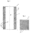
- a burner element 1 shown in FIG. 1 exists from a substantially hollow cylindrical Ceramic jacket 2, which consists of six plate-shaped ceramic elements 3, which are arranged with respect to one another, that they form a closed polygon. End the burner element 1 each has an annular element 4 or 5, which are U-shaped in cross section are, the two legs 6 of the annular Element 4 or 5 on the outer surface 7 of the ceramic jacket 2 concerns.
- the annular element 5 has one in its Center arranged bore 8 at least two in a uniform Distance to the bore 8 arranged openings 9, through which a gas-air mixture in the interior 10 of the Burner element 1 flows.
- the inflow direction of the gas-air mixture is represented by the arrows 11.
- the annular element 4 has compared to the annular Element 5 only one arranged in its center Bore 12, which is coaxial with the bore 8 in the annular Element 5 is arranged and which holes 8th and 12 are penetrated by a threaded rod 13.
- the Threaded rod 13 has a screwed on the outside Mother 14, which each have a Washer 15 on the end face 16 of the annular Elements 4 and 5 are supported.
- the threaded rod 13 forms the nuts 14 and the washers 15 a tie rod.
- distributor element 17 In the immediate area of the annular element 5 inside the interior 10 there is a distributor element 17 the threaded rod 13 attached, which distributor element 17th the gas-air mixture flowing in the direction of arrows 11 evenly on the inner wall 18 of the ceramic jacket 2 distributed so that the gas-air mixture through a variety of passage channels 19 in the area of the outer surface 7 arrives where the gas-air mixture for heating is burned.
- the passage channels 19 are evenly spaced from one another over the entire outer surface 7 of the burner element 1 distributed so that the passage channels 19 form a pinhole image.
- the flow direction of the gas-air mixture from the interior 10 through the passage channels 19 is through the arrows 20 indicated.
- FIG. 2 is a second embodiment of the burner element 1, which differs only from the first embodiment of the burner element 1 according to FIG. 1 distinguishes that some of the through channels 19 in one dome-shaped opening 21 which ends in the surface area the outer surface 7 are arranged.
- the respective ceramic jackets 2 are two embodiments shown in FIGS. 1 and 2. It can be clearly seen that the ceramic jacket 2 has an interior 10 open on both sides, which 1 and 2 by the annular elements 4th or 5 is completed. 4 and 6 show a section of the surface of the Outer lateral surface 7, which can be clearly seen in FIG. 4 is that the passage channels 19 have the same diameter, the passageways 19 overall a close-knit Form pinhole pattern. In comparison, the Fig. 6 additionally the arrangement of the dome-shaped Openings, each seven adjacent Combine passage channels 19. The surface of the 5 is the outer surface 7 of the ceramic shell 2 thus structured, whereas the surface of the Outer lateral surface 7 of the ceramic jacket 2 according to FIG. 3 a has a smooth surface.
- FIG. 7 is the outer surface 7 of the ceramic shell 2 in essentially corresponding to the lateral surface of a cylinder formed, whereas the inner wall 18 of the ceramic jacket 2 is polygonal.
- the neighboring ceramic elements 3 are mitered along their longitudinal edges 22 worked and in such a way that the longitudinal edges 22 of the Ceramic elements 3 radially to the outer surface 7 of the Ceramic jacket 2 run. Between neighboring ceramic elements 3 is also in the outer surface 7 in Area of the longitudinal edges 22 each in the longitudinal direction of the ceramic jacket 2 extending groove-shaped depression ordered.
- the individual ceramic elements 3 according to the embodiments 7 and 8 are on the one hand by the annular Elements 4 and 5 connected together. On the other hand can between the adjacent ceramic elements 3 Adhesive to be applied to the longitudinal edges 22, the Adjacent ceramic elements 3 glued together.
- FIGS. 9 and 10 differ In contrast, the embodiments according to FIGS. 7 and 8 in that between adjacent ceramic elements 3, a ceramic seal 24 is arranged.
- This Seals 24 serve to seal the neighboring ones Ceramic elements 3 made exclusively by the front arranged ring-shaped elements 4 and 5 with each other are connected.
- a burner element 1 according to FIG. 1 and / or 2 made of ceramic material for a radiant burner, especially for an infrared radiation burner, that with liquid or gaseous, in particular fossil fuels can be operated, it is provided that several, preferably six ceramic elements 3 in one closed polygon arranged and interconnected will.
- the originally cuboid ceramic elements 3 on its outer lateral surface 7 in the form of a segment of a circular arc sanded and then the longitudinal edges 22 of each ceramic element 3 mitred will.
- the Longitudinal edges 22 with a temperature-resistant ceramic adhesive are coated before the longitudinal edges 22 are adjacent Ceramic elements 3 are glued together.
- the ceramic element 2 with the two can annular elements 4 and 5 are provided at the ends, which are then clamped together via the threaded rod 13 . It should be ensured that the on the Ceramic elements 3 transmitted axial pressure not too high is, so that damage to the Ceramic elements 3 can not be done.
- Ceramic between adjacent ceramic elements Seals 24 are arranged.
- This ceramic Seals 24 consist of mat-like structures, which the space between adjacent ceramic elements 3 seal.
- the ceramic elements 3 in a first step their outer lateral surfaces 7 in the shape of a circular arc grind, then the ground ceramic elements 3 to assemble the ceramic jacket 2 and finally the at this point, the inner wall is still polygonal 18 parallel to the outer surface 7 to grind.
- advantage this latter possibility is that a more uniform Result achievable in the area of the inner wall 18 is, whereas the advantage of the former possibility the inventive method of producing an inventive Burner element 1 is that the grinding the individual ceramic elements 3 technically less expensive is.
Landscapes
- Engineering & Computer Science (AREA)
- Chemical & Material Sciences (AREA)
- Combustion & Propulsion (AREA)
- Mechanical Engineering (AREA)
- General Engineering & Computer Science (AREA)
- Gas Burners (AREA)
Applications Claiming Priority (2)
| Application Number | Priority Date | Filing Date | Title |
|---|---|---|---|
| DE19627103A DE19627103C1 (de) | 1996-07-05 | 1996-07-05 | Brennerelement |
| DE19627103 | 1996-07-05 |
Publications (3)
| Publication Number | Publication Date |
|---|---|
| EP0816757A2 true EP0816757A2 (fr) | 1998-01-07 |
| EP0816757A3 EP0816757A3 (fr) | 1999-03-31 |
| EP0816757B1 EP0816757B1 (fr) | 2005-08-24 |
Family
ID=7799024
Family Applications (1)
| Application Number | Title | Priority Date | Filing Date |
|---|---|---|---|
| EP97109528A Expired - Lifetime EP0816757B1 (fr) | 1996-07-05 | 1997-06-12 | Elément de brûleur |
Country Status (3)
| Country | Link |
|---|---|
| EP (1) | EP0816757B1 (fr) |
| DE (2) | DE19627103C1 (fr) |
| ES (1) | ES2248828T3 (fr) |
Cited By (4)
| Publication number | Priority date | Publication date | Assignee | Title |
|---|---|---|---|---|
| EP0950853A2 (fr) | 1998-04-18 | 1999-10-20 | Bray Technologies Plc | Brûleurs à prémélange combustible/air |
| WO2009065733A1 (fr) * | 2007-11-19 | 2009-05-28 | Sit La Precisa S.P.A. Con Socio Unico | Brûleur, en particulier brûleur à prémélange |
| ITPN20100034A1 (it) * | 2010-06-08 | 2011-12-09 | Giorik Spa | Bruciatore premiscelato in particolare per forni di cottura |
| CN103851619A (zh) * | 2012-12-07 | 2014-06-11 | 青岛瑞迪燃气具制造有限公司 | 一种红外燃烧机燃烧板 |
Families Citing this family (3)
| Publication number | Priority date | Publication date | Assignee | Title |
|---|---|---|---|---|
| DE10132578B4 (de) * | 2001-07-10 | 2007-04-26 | Forschungszentrum Jülich GmbH | Verfahren zum Verbinden von metallischen und/oder keramischen Formteilen |
| JP4034749B2 (ja) * | 2004-03-29 | 2008-01-16 | リンナイ株式会社 | 筒状バーナ |
| JP3996139B2 (ja) * | 2004-03-29 | 2007-10-24 | リンナイ株式会社 | 筒状バーナ |
Citations (2)
| Publication number | Priority date | Publication date | Assignee | Title |
|---|---|---|---|---|
| EP0382674A2 (fr) | 1989-02-06 | 1990-08-16 | Carrier Corporation | Methode de fabrication d'un brûleur infrarouge |
| EP0536706A2 (fr) | 1991-10-08 | 1993-04-14 | Lüdi, Roger | Procédé pour la fabrication d'un stabilisateur de flamme pour un brûleur radiant et stabilisateur de flamme produit selon ce procédé |
Family Cites Families (6)
| Publication number | Priority date | Publication date | Assignee | Title |
|---|---|---|---|---|
| DE1815256A1 (de) * | 1968-12-18 | 1970-07-09 | Schwank Gasgeraete Gmbh | Infrarotstrahler |
| FR2051066A5 (en) * | 1969-06-14 | 1971-04-02 | Schwank Gmbh | Infra red radiation device |
| FR2503836A1 (fr) * | 1981-04-10 | 1982-10-15 | Vaneecke Solaronics | Bruleur multiflammes |
| FR2534353A1 (fr) * | 1982-10-11 | 1984-04-13 | Vaneecke Solaronics | Plaquette a face rayonnante alveolee pour bruleur radiant |
| US5085579A (en) * | 1991-03-25 | 1992-02-04 | Mor-Flo Industries, Inc. | Powered chamber combustion system and burner therefor |
| NL1001688C2 (nl) * | 1995-11-17 | 1997-05-21 | Furigas Assen Bv | Brander met gesegmenteerd branderdek. |
-
1996
- 1996-07-05 DE DE19627103A patent/DE19627103C1/de not_active Expired - Fee Related
-
1997
- 1997-06-12 DE DE59712400T patent/DE59712400D1/de not_active Expired - Fee Related
- 1997-06-12 EP EP97109528A patent/EP0816757B1/fr not_active Expired - Lifetime
- 1997-06-12 ES ES97109528T patent/ES2248828T3/es not_active Expired - Lifetime
Patent Citations (2)
| Publication number | Priority date | Publication date | Assignee | Title |
|---|---|---|---|---|
| EP0382674A2 (fr) | 1989-02-06 | 1990-08-16 | Carrier Corporation | Methode de fabrication d'un brûleur infrarouge |
| EP0536706A2 (fr) | 1991-10-08 | 1993-04-14 | Lüdi, Roger | Procédé pour la fabrication d'un stabilisateur de flamme pour un brûleur radiant et stabilisateur de flamme produit selon ce procédé |
Cited By (5)
| Publication number | Priority date | Publication date | Assignee | Title |
|---|---|---|---|---|
| EP0950853A2 (fr) | 1998-04-18 | 1999-10-20 | Bray Technologies Plc | Brûleurs à prémélange combustible/air |
| WO2009065733A1 (fr) * | 2007-11-19 | 2009-05-28 | Sit La Precisa S.P.A. Con Socio Unico | Brûleur, en particulier brûleur à prémélange |
| ITPN20100034A1 (it) * | 2010-06-08 | 2011-12-09 | Giorik Spa | Bruciatore premiscelato in particolare per forni di cottura |
| CN103851619A (zh) * | 2012-12-07 | 2014-06-11 | 青岛瑞迪燃气具制造有限公司 | 一种红外燃烧机燃烧板 |
| CN103851619B (zh) * | 2012-12-07 | 2016-11-23 | 青岛瑞迪燃气具制造有限公司 | 一种红外燃烧机燃烧板 |
Also Published As
| Publication number | Publication date |
|---|---|
| ES2248828T3 (es) | 2006-03-16 |
| EP0816757A3 (fr) | 1999-03-31 |
| DE59712400D1 (de) | 2005-09-29 |
| DE19627103C1 (de) | 1997-07-24 |
| EP0816757B1 (fr) | 2005-08-24 |
Similar Documents
| Publication | Publication Date | Title |
|---|---|---|
| EP0505719B1 (fr) | Articulation à rotule | |
| DE1510359C3 (de) | Walze zum Entwässern von Fasersuspensionen | |
| DE69318526T2 (de) | Verbindungsanordnung für Bauelemente aus Kunstharz | |
| DE2834864B2 (de) | Laufschaufel für eine Gasturbine | |
| EP1008191A1 (fr) | Actionneur piezoelectrique precontraint | |
| EP0396151A2 (fr) | Procédé pour fabriquer une connexion de bride de tuyau | |
| EP3479002B1 (fr) | Procédé d'assemblage d'éléments tubulaires | |
| WO2008044105A1 (fr) | Traversée électrique, notamment pour des applications de pression, et procédé de fabrication d'une telle traversée | |
| DE19627103C1 (de) | Brennerelement | |
| DE1964981A1 (de) | Zerstaeuberduese fuer Fluessigkeiten und Gase und Verfahren zu deren Herstellung | |
| DE69006530T2 (de) | Mit Ventilen versehenes Verzweigungsgehäuse. | |
| DE9308677U1 (de) | Befestigungselement zum lösbaren Verbinden eines Mehrkantrohres, vorzugsweise eines Vierkantrohres | |
| WO2014005751A2 (fr) | Brûleur à système de combustion superficielle | |
| EP1270132A2 (fr) | Corps de base constitué de tronçons de tube joints et procédé de fabrication | |
| DE102009053683B4 (de) | Filterelement mit Mittelrohr | |
| DE69230108T2 (de) | Kupplungsvorrichtung | |
| DE29622773U1 (de) | Brennerelement | |
| DE19609168C2 (de) | Zusammengesetzter Dekorationskörper, insbesondere Dekorationsstern, bestehend aus einem Trägerkörper und daran befestigten als pyramidenförmige Spitzen ausgebildeten Teilen und Verfahren zu dessen Herstellung | |
| DE29505791U1 (de) | Befestigungselement zum lösbaren Verbinden eines Mehrkantrohres | |
| EP0489231A1 (fr) | Aérateur pour liquides | |
| DE2648915B2 (de) | Ventilgehäuse | |
| WO1992019404A1 (fr) | Procede pour la realisation de rainures de commande dans une douille de commande | |
| DE4030135C2 (de) | Düsenkranz für einen Flüssigpropangasbrenner für Heißluftballons sowie ein Verfahren zur Herstellung | |
| DE60129780T2 (de) | Rohrstruktur, Strömungskanalstruktur und Wärmetauscher | |
| CH682006A5 (en) | Flange coupling for pipe connection |
Legal Events
| Date | Code | Title | Description |
|---|---|---|---|
| PUAI | Public reference made under article 153(3) epc to a published international application that has entered the european phase |
Free format text: ORIGINAL CODE: 0009012 |
|
| AK | Designated contracting states |
Kind code of ref document: A2 Designated state(s): BE DE ES IT NL |
|
| PUAL | Search report despatched |
Free format text: ORIGINAL CODE: 0009013 |
|
| AK | Designated contracting states |
Kind code of ref document: A3 Designated state(s): AT BE CH DE DK ES FI FR GB GR IE IT LI LU MC NL PT SE |
|
| 17P | Request for examination filed |
Effective date: 19990924 |
|
| AKX | Designation fees paid |
Free format text: BE DE ES IT NL |
|
| 17Q | First examination report despatched |
Effective date: 20020503 |
|
| GRAP | Despatch of communication of intention to grant a patent |
Free format text: ORIGINAL CODE: EPIDOSNIGR1 |
|
| GRAS | Grant fee paid |
Free format text: ORIGINAL CODE: EPIDOSNIGR3 |
|
| GRAA | (expected) grant |
Free format text: ORIGINAL CODE: 0009210 |
|
| AK | Designated contracting states |
Kind code of ref document: B1 Designated state(s): BE DE ES IT NL |
|
| REF | Corresponds to: |
Ref document number: 59712400 Country of ref document: DE Date of ref document: 20050929 Kind code of ref document: P |
|
| REG | Reference to a national code |
Ref country code: ES Ref legal event code: FG2A Ref document number: 2248828 Country of ref document: ES Kind code of ref document: T3 |
|
| PGFP | Annual fee paid to national office [announced via postgrant information from national office to epo] |
Ref country code: NL Payment date: 20060622 Year of fee payment: 10 |
|
| PGFP | Annual fee paid to national office [announced via postgrant information from national office to epo] |
Ref country code: ES Payment date: 20060629 Year of fee payment: 10 |
|
| PGFP | Annual fee paid to national office [announced via postgrant information from national office to epo] |
Ref country code: IT Payment date: 20060630 Year of fee payment: 10 Ref country code: BE Payment date: 20060630 Year of fee payment: 10 |
|
| PLBE | No opposition filed within time limit |
Free format text: ORIGINAL CODE: 0009261 |
|
| STAA | Information on the status of an ep patent application or granted ep patent |
Free format text: STATUS: NO OPPOSITION FILED WITHIN TIME LIMIT |
|
| 26N | No opposition filed |
Effective date: 20060526 |
|
| PG25 | Lapsed in a contracting state [announced via postgrant information from national office to epo] |
Ref country code: DE Free format text: LAPSE BECAUSE OF NON-PAYMENT OF DUE FEES Effective date: 20070103 |
|
| BERE | Be: lapsed |
Owner name: *SCHWANK G.M.B.H. Effective date: 20070630 |
|
| NLV4 | Nl: lapsed or anulled due to non-payment of the annual fee |
Effective date: 20080101 |
|
| PG25 | Lapsed in a contracting state [announced via postgrant information from national office to epo] |
Ref country code: BE Free format text: LAPSE BECAUSE OF NON-PAYMENT OF DUE FEES Effective date: 20070630 |
|
| PG25 | Lapsed in a contracting state [announced via postgrant information from national office to epo] |
Ref country code: NL Free format text: LAPSE BECAUSE OF NON-PAYMENT OF DUE FEES Effective date: 20080101 |
|
| REG | Reference to a national code |
Ref country code: ES Ref legal event code: FD2A Effective date: 20070613 |
|
| PG25 | Lapsed in a contracting state [announced via postgrant information from national office to epo] |
Ref country code: ES Free format text: LAPSE BECAUSE OF NON-PAYMENT OF DUE FEES Effective date: 20070613 |
|
| PG25 | Lapsed in a contracting state [announced via postgrant information from national office to epo] |
Ref country code: IT Free format text: LAPSE BECAUSE OF NON-PAYMENT OF DUE FEES Effective date: 20070612 |