EP0816775A2 - Chauffe-eau à circulation à gaz - Google Patents
Chauffe-eau à circulation à gaz Download PDFInfo
- Publication number
- EP0816775A2 EP0816775A2 EP97108554A EP97108554A EP0816775A2 EP 0816775 A2 EP0816775 A2 EP 0816775A2 EP 97108554 A EP97108554 A EP 97108554A EP 97108554 A EP97108554 A EP 97108554A EP 0816775 A2 EP0816775 A2 EP 0816775A2
- Authority
- EP
- European Patent Office
- Prior art keywords
- combustion chamber
- water
- heat exchanger
- lamella
- water heater
- Prior art date
- Legal status (The legal status is an assumption and is not a legal conclusion. Google has not performed a legal analysis and makes no representation as to the accuracy of the status listed.)
- Granted
Links
Images

Classifications
-
- F—MECHANICAL ENGINEERING; LIGHTING; HEATING; WEAPONS; BLASTING
- F24—HEATING; RANGES; VENTILATING
- F24H—FLUID HEATERS, e.g. WATER OR AIR HEATERS, HAVING HEAT-GENERATING MEANS, e.g. HEAT PUMPS, IN GENERAL
- F24H1/00—Water heaters, e.g. boilers, continuous-flow heaters or water-storage heaters
- F24H1/22—Water heaters other than continuous-flow or water-storage heaters, e.g. water heaters for central heating
- F24H1/40—Water heaters other than continuous-flow or water-storage heaters, e.g. water heaters for central heating with water tube or tubes
-
- F—MECHANICAL ENGINEERING; LIGHTING; HEATING; WEAPONS; BLASTING
- F24—HEATING; RANGES; VENTILATING
- F24H—FLUID HEATERS, e.g. WATER OR AIR HEATERS, HAVING HEAT-GENERATING MEANS, e.g. HEAT PUMPS, IN GENERAL
- F24H1/00—Water heaters, e.g. boilers, continuous-flow heaters or water-storage heaters
- F24H1/22—Water heaters other than continuous-flow or water-storage heaters, e.g. water heaters for central heating
- F24H1/24—Water heaters other than continuous-flow or water-storage heaters, e.g. water heaters for central heating with water mantle surrounding the combustion chamber or chambers
-
- F—MECHANICAL ENGINEERING; LIGHTING; HEATING; WEAPONS; BLASTING
- F24—HEATING; RANGES; VENTILATING
- F24H—FLUID HEATERS, e.g. WATER OR AIR HEATERS, HAVING HEAT-GENERATING MEANS, e.g. HEAT PUMPS, IN GENERAL
- F24H1/00—Water heaters, e.g. boilers, continuous-flow heaters or water-storage heaters
- F24H1/22—Water heaters other than continuous-flow or water-storage heaters, e.g. water heaters for central heating
- F24H1/44—Water heaters other than continuous-flow or water-storage heaters, e.g. water heaters for central heating with combinations of two or more of the types covered by groups F24H1/24 - F24H1/40
-
- F—MECHANICAL ENGINEERING; LIGHTING; HEATING; WEAPONS; BLASTING
- F24—HEATING; RANGES; VENTILATING
- F24H—FLUID HEATERS, e.g. WATER OR AIR HEATERS, HAVING HEAT-GENERATING MEANS, e.g. HEAT PUMPS, IN GENERAL
- F24H9/00—Details
- F24H9/0005—Details for water heaters
- F24H9/0036—Dispositions against condensation of combustion products
-
- F—MECHANICAL ENGINEERING; LIGHTING; HEATING; WEAPONS; BLASTING
- F28—HEAT EXCHANGE IN GENERAL
- F28F—DETAILS OF HEAT-EXCHANGE AND HEAT-TRANSFER APPARATUS, OF GENERAL APPLICATION
- F28F1/00—Tubular elements; Assemblies of tubular elements
- F28F1/10—Tubular elements and assemblies thereof with means for increasing heat-transfer area, e.g. with fins, with projections, with recesses
- F28F1/12—Tubular elements and assemblies thereof with means for increasing heat-transfer area, e.g. with fins, with projections, with recesses the means being only outside the tubular element
- F28F1/24—Tubular elements and assemblies thereof with means for increasing heat-transfer area, e.g. with fins, with projections, with recesses the means being only outside the tubular element and extending transversely
- F28F1/32—Tubular elements and assemblies thereof with means for increasing heat-transfer area, e.g. with fins, with projections, with recesses the means being only outside the tubular element and extending transversely the means having portions engaging further tubular elements
-
- F—MECHANICAL ENGINEERING; LIGHTING; HEATING; WEAPONS; BLASTING
- F28—HEAT EXCHANGE IN GENERAL
- F28F—DETAILS OF HEAT-EXCHANGE AND HEAT-TRANSFER APPARATUS, OF GENERAL APPLICATION
- F28F21/00—Constructions of heat-exchange apparatus characterised by the selection of particular materials
- F28F21/08—Constructions of heat-exchange apparatus characterised by the selection of particular materials of metal
- F28F21/081—Heat exchange elements made from metals or metal alloys
- F28F21/082—Heat exchange elements made from metals or metal alloys from steel or ferrous alloys
- F28F21/083—Heat exchange elements made from metals or metal alloys from steel or ferrous alloys from stainless steel
-
- F—MECHANICAL ENGINEERING; LIGHTING; HEATING; WEAPONS; BLASTING
- F28—HEAT EXCHANGE IN GENERAL
- F28F—DETAILS OF HEAT-EXCHANGE AND HEAT-TRANSFER APPARATUS, OF GENERAL APPLICATION
- F28F21/00—Constructions of heat-exchange apparatus characterised by the selection of particular materials
- F28F21/08—Constructions of heat-exchange apparatus characterised by the selection of particular materials of metal
- F28F21/081—Heat exchange elements made from metals or metal alloys
- F28F21/085—Heat exchange elements made from metals or metal alloys from copper or copper alloys
Definitions
- the invention is based on a gas-heated circulation water heater according to the genus of the main claim.
- Both Known water heaters of this type is the one Combustion chamber cooling line section to a between the Return connection and the input of the heat exchanger connected location of the pipe system.
- the water cooling the combustion chamber has no arrangement or only slightly above the temperature of the heating return water lying temperature so that it is in operation in the low temperature range or in partial load operation Condensation can form on the combustion chamber walls.
- features of the main claim have the advantage that the water flowing along the combustion chamber walls in Heat exchanger is heated, so that only at extreme low return temperatures (less than 25 ° C) condensate in small quantities, the one in the bottom Channels arranged at the edge of the combustion chamber until evaporation or Evaporation can be absorbed.
- a fitting, monitoring, cleaning and if necessary, the exchange of the gas burner and the Heat transfer facilitating design results when the combustion chamber with a separately designed, detachable its side walls attachable front wall is provided.
- the Front wall is also cooled by a Line section, the input side downstream of the Heat exchanger is connected to the pipe system.
- the line section cooling the front wall is advantageously dimensioned so and on the output side so that Line system connected that he as a device bypass for the minimum amount of circulating water is used. This is except one good cooling of the front wall is also a requirement for one good control behavior created how they secure the Represents minimum quantity in circulation. So far for this purpose in the case of devices with domestic hot water preparation, changeover valves with defined leakage used. Let these valves in the arrangement according to the invention by the general Replace the used types with a tight seal.
- Stainless steel wall panels are made using local Formations for the formation of channels for the heating water are provided, the condensation and the Corrosion attack can be further counteracted, if the wall panels are through along the channel edges running welds are interconnected and the Channels after welding by molding the between the welded sheet metal areas by means of one inserted with pressure between the wall plates fluid or gaseous working fluid are formed.
- Ratio of flow cross-section of the channels to the Reach wall surfaces of the combustion chamber can be particularly cheap Ratio of flow cross-section of the channels to the Reach wall surfaces of the combustion chamber.
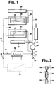
- Figure 1 shows schematically the network plan of a Circulation water heater for heating and domestic water heating
- Figure 2 shows a partial section through a wall of the combustion chamber of the water heater according to Figure 1
- Figure 3 is a side view a lamella of the heat exchanger of the water heater Figure 1
- Figure 4 shows a section along the line IV-IV in Figure 3.
- the circulating water heater has a return connection 10 for one indicated heating network 12, of which a line 14 via a changeover valve 16 leads to the input of a pump 18, whose output via a line 20 with a cooling section in a gas burner 22 is connected.
- a line 14 via a changeover valve 16 leads to the input of a pump 18, whose output via a line 20 with a cooling section in a gas burner 22 is connected.
- From the heat exchanger 26 leads a line 30 to the input one in the rear wall and the Sidewalls of the combustion chamber 28 integrated, below line section 32 described in more detail, whose Output via a line 34 with a flow connection 36 is connected to the heating network 12.
- To line 34 is a branch line 38 connected by a Heat exchanger 40 for process water through to Changeover valve 16 leads.
- the front wall 41 of the combustion chamber 28 is separate Component executed that releasably on the side walls of the Combustion chamber is attachable.
- the front wall 41 is one own line section 42 integrated, the input side connected via line 44 to line 34 and on the output side via a line 46 to the input of the Pump 18 is connected.
- the walls of the combustion chamber 28 are as can be seen from FIG. 2, each made of 2 wall sheets 48.50 Made of stainless steel, the specified seam lines 52 welded together and then between the seam lines 52 by a fluid gaseous working medium under pressure are deformed to form channels.
- the channels 54 in the Form rear wall and in the side walls of the combustion chamber 28 the line section 32, whereas the channels 54 in the Front wall 41 form the line section 42.
- the flow resistance of the line section 42 is so dimensioned that the line connection from the exit of the Line section 32 to the input of the pump 18 as Device bypass serves for the minimum amount of circulating water. That's why is a commonly used type for the switching valve 16 provided with a tight seal. That in the Pipe sections 32 and 42 flowing water is in the Heat exchanger 26 heated up so far that condensate the combustion chamber walls only when operating in Low temperature range or in low load operation in low Can form sets.
- the special procedure for forming the Channels 54 in the combustion chamber walls also ensure that gaps between the wall plates 48.50 to the Can not form longitudinal edges of the channels 54, whereby corrosion of the combustion chamber is also counteracted becomes.
- the heat exchanger 26 is a lamella block with fins 56 made of ferritic stainless steel and passed through Water pipes 58 made of copper. Each slat is 56 at their passage opening with a collar-like passage 60 provided which tightly encloses the water pipe 58. Of the combustion chamber side edge 62 of the fins 56 is between the Water pipes 58 pulled up to the so-called Limit light length not to be exceeded, d. i.e. to a The slats 56 overheat in these areas avoid. Between the edge 62 and the combustion chamber side Peak areas of the passages 60 result Slat areas 64, the height h as large as that Evaporation distance is dimensioned, along which the Passages 60 formed or accumulating condensate 66th evaporates.
- the length of the evaporation path depends on the temperature of water in the respective water pipe 58 and may not exceed correspond to the limit incandescent length.
- Slat wall thickness can be ensured that the Limit light length at least as large as the required Inlet section at the lamella areas 64.
- the height h n in the lamella areas 64 is gradually reduced towards the output of the heat exchanger down to the value h 1 .
- the lamella areas 68 encompassing the upper apex areas of the water pipes 58 are increasingly of dimension b towards the exit of the heat exchanger n shortened to dimension b 1 .
- the measures described above are combined with the feature that the free distance d between two adjacent slats 56 not the dimension of 2.7 mm exceeds. This ensures that Capillary action of the condensate on the fins 56 to is held for its evaporation.
- the distance is d determined by the height a of the passage 60 on the lamella 56, at the bend radius of the adjacent lamella passage is present.
- the surface of the Water pipes 58 completely through the precious metal of the fins covered, so that there are none at these points Can form corrosion products.
- the Width e and its length k are such that they are the Slat gaps at least over the closest distance l cover approximately between the water pipes 58. Thereby prevents that above the heat exchanger The resulting corrosion products fall through on the burner.
Landscapes
- Engineering & Computer Science (AREA)
- Physics & Mathematics (AREA)
- Thermal Sciences (AREA)
- Mechanical Engineering (AREA)
- General Engineering & Computer Science (AREA)
- Chemical & Material Sciences (AREA)
- Combustion & Propulsion (AREA)
- Geometry (AREA)
- Instantaneous Water Boilers, Portable Hot-Water Supply Apparatuses, And Control Of Portable Hot-Water Supply Apparatuses (AREA)
Applications Claiming Priority (2)
| Application Number | Priority Date | Filing Date | Title |
|---|---|---|---|
| DE19626321A DE19626321A1 (de) | 1996-07-01 | 1996-07-01 | Gasbeheizter Umlauf-Wasserheizer |
| DE19626321 | 1996-07-01 |
Publications (3)
| Publication Number | Publication Date |
|---|---|
| EP0816775A2 true EP0816775A2 (fr) | 1998-01-07 |
| EP0816775A3 EP0816775A3 (fr) | 1998-12-23 |
| EP0816775B1 EP0816775B1 (fr) | 2002-09-25 |
Family
ID=7798530
Family Applications (1)
| Application Number | Title | Priority Date | Filing Date |
|---|---|---|---|
| EP97108554A Expired - Lifetime EP0816775B1 (fr) | 1996-07-01 | 1997-05-28 | Chauffe-eau à circulation à gaz |
Country Status (2)
| Country | Link |
|---|---|
| EP (1) | EP0816775B1 (fr) |
| DE (2) | DE19626321A1 (fr) |
Cited By (1)
| Publication number | Priority date | Publication date | Assignee | Title |
|---|---|---|---|---|
| EP1271063A1 (fr) * | 2001-06-18 | 2003-01-02 | Bruno Della Gaspera | Echangeur de chaleur, notamment plinthe chauffante |
Families Citing this family (1)
| Publication number | Priority date | Publication date | Assignee | Title |
|---|---|---|---|---|
| EP0994321B1 (fr) * | 1998-10-13 | 2004-08-18 | Robert Bosch Gmbh | Echangeur de chaleur pour chauffe-eau chauffé par combustible |
Family Cites Families (6)
| Publication number | Priority date | Publication date | Assignee | Title |
|---|---|---|---|---|
| FR2050273A1 (fr) * | 1969-07-11 | 1971-04-02 | Calotech Ets | |
| DE2742854C2 (de) * | 1977-09-23 | 1985-05-02 | Robert Bosch Gmbh, 7000 Stuttgart | Wassererhitzer mit einem Gas- oder Ölbrenner |
| NL8403088A (nl) * | 1984-10-10 | 1986-05-01 | Fasto Bv | Geiser voor het bereiden van warm water. |
| FR2595796B1 (fr) * | 1986-03-14 | 1988-06-17 | Chaffoteaux Et Maury | Perfectionnements aux corps de chauffe pour chauffe-eau a gaz |
| JP3030036B2 (ja) * | 1989-08-23 | 2000-04-10 | 昭和アルミニウム株式会社 | 複式熱交換器 |
| DE4224212A1 (de) * | 1991-07-22 | 1993-01-28 | Vaillant Joh Gmbh & Co | Doppelwandiger heizschacht |
-
1996
- 1996-07-01 DE DE19626321A patent/DE19626321A1/de not_active Withdrawn
-
1997
- 1997-05-28 DE DE59708303T patent/DE59708303D1/de not_active Expired - Lifetime
- 1997-05-28 EP EP97108554A patent/EP0816775B1/fr not_active Expired - Lifetime
Non-Patent Citations (1)
| Title |
|---|
| None |
Cited By (2)
| Publication number | Priority date | Publication date | Assignee | Title |
|---|---|---|---|---|
| EP1271063A1 (fr) * | 2001-06-18 | 2003-01-02 | Bruno Della Gaspera | Echangeur de chaleur, notamment plinthe chauffante |
| WO2002103246A3 (fr) * | 2001-06-18 | 2003-03-20 | Gaspera Bruno Della | Dispositif d'echange thermique, notamment plinthes chauffantes |
Also Published As
| Publication number | Publication date |
|---|---|
| EP0816775A3 (fr) | 1998-12-23 |
| DE19626321A1 (de) | 1998-01-08 |
| EP0816775B1 (fr) | 2002-09-25 |
| DE59708303D1 (de) | 2002-10-31 |
Similar Documents
| Publication | Publication Date | Title |
|---|---|---|
| DE2725239A1 (de) | Waermeaustauschsystem und metalltafel fuer ein waermeaustauschsystem | |
| DE102006048305A1 (de) | Plattenwärmetauscher | |
| DE69900133T2 (de) | Gas-Flüssigkeitswärmetauscher und Verfahren zu dessen Herstellung | |
| DE2820832B2 (de) | Wasserrohrkessel für eine Sammelheizungsanlage | |
| EP0816775B1 (fr) | Chauffe-eau à circulation à gaz | |
| EP1832830B1 (fr) | Echangeur de chaleur | |
| CH634642A5 (de) | Rauchrohr fuer heizkessel. | |
| DE102017009424A1 (de) | Wärmetransferelement, das in einem Strömungsweg eines Wärmetauschers anzuordnen ist | |
| DE102007010585A1 (de) | Wasserregister für einen Ofen, Wärmetauscher hierfür, sowie Verfahren zu deren Herstellung | |
| DE69613944T2 (de) | Meanderförmiger,kombinierter Wärmetauscher mit komplexer,gerader Strecke | |
| DE2126226C3 (de) | Wärmeaustauscher | |
| EP0595945B1 (fr) | Section de chauffage a double paroi | |
| DE3205121C2 (de) | Heizungskessel | |
| EP0195383A2 (fr) | Chaudière à condensation | |
| DE3049805A1 (en) | Heating plant | |
| EP0493665B2 (fr) | Echangeur de chaleur et procédé de production d'une lamelle pour un échangeur de chaleur | |
| DE102006013868A1 (de) | Abgaswärmeübertrager, insbesondere Abgaskühler für eine Abgasrückführung in Kraftfahrzeugen | |
| AT404756B (de) | Wärmetauscher | |
| DE2252405A1 (de) | Waermetauscher, insbesondere fuer warmwassergeraete im haushalt | |
| DE19628708B4 (de) | Wasserheizanlage | |
| EP0816776A2 (fr) | Chauffe-eau à gaz et chambre de combustion refroidie par eau | |
| AT398627B (de) | Heizkessel | |
| DE102008060413A1 (de) | Wärmetauscher für einen Heizkessel, insbesondere Brennwertkessel | |
| AT371588B (de) | Anordnung zur ausnutzung der abluftwaerme aus staellen od.dgl. | |
| DE4306299C2 (de) | Wärmetauscher für einen Brennwertkessel |
Legal Events
| Date | Code | Title | Description |
|---|---|---|---|
| PUAI | Public reference made under article 153(3) epc to a published international application that has entered the european phase |
Free format text: ORIGINAL CODE: 0009012 |
|
| AK | Designated contracting states |
Kind code of ref document: A2 Designated state(s): DE ES FR GB IT NL |
|
| PUAL | Search report despatched |
Free format text: ORIGINAL CODE: 0009013 |
|
| AK | Designated contracting states |
Kind code of ref document: A3 Designated state(s): AT BE CH DE DK ES FI FR GB GR IE IT LI LU MC NL PT SE |
|
| 17P | Request for examination filed |
Effective date: 19990623 |
|
| AKX | Designation fees paid |
Free format text: DE ES FR GB IT NL |
|
| 17Q | First examination report despatched |
Effective date: 20001218 |
|
| GRAG | Despatch of communication of intention to grant |
Free format text: ORIGINAL CODE: EPIDOS AGRA |
|
| GRAG | Despatch of communication of intention to grant |
Free format text: ORIGINAL CODE: EPIDOS AGRA |
|
| GRAH | Despatch of communication of intention to grant a patent |
Free format text: ORIGINAL CODE: EPIDOS IGRA |
|
| GRAH | Despatch of communication of intention to grant a patent |
Free format text: ORIGINAL CODE: EPIDOS IGRA |
|
| GRAA | (expected) grant |
Free format text: ORIGINAL CODE: 0009210 |
|
| AK | Designated contracting states |
Kind code of ref document: B1 Designated state(s): DE ES FR GB IT NL |
|
| PG25 | Lapsed in a contracting state [announced via postgrant information from national office to epo] |
Ref country code: NL Free format text: LAPSE BECAUSE OF FAILURE TO SUBMIT A TRANSLATION OF THE DESCRIPTION OR TO PAY THE FEE WITHIN THE PRESCRIBED TIME-LIMIT Effective date: 20020925 Ref country code: IT Free format text: LAPSE BECAUSE OF FAILURE TO SUBMIT A TRANSLATION OF THE DESCRIPTION OR TO PAY THE FEE WITHIN THE PRE;WARNING: LAPSES OF ITALIAN PATENTS WITH EFFECTIVE DATE BEFORE 2007 MAY HAVE OCCURRED AT ANY TIME BEFORE 2007. THE CORRECT EFFECTIVE DATE MAY BE DIFFERENT FROM THE ONE RECORDED.SCRIBED TIME-LIMIT Effective date: 20020925 Ref country code: GB Free format text: LAPSE BECAUSE OF FAILURE TO SUBMIT A TRANSLATION OF THE DESCRIPTION OR TO PAY THE FEE WITHIN THE PRESCRIBED TIME-LIMIT Effective date: 20020925 Ref country code: FR Free format text: LAPSE BECAUSE OF FAILURE TO SUBMIT A TRANSLATION OF THE DESCRIPTION OR TO PAY THE FEE WITHIN THE PRESCRIBED TIME-LIMIT Effective date: 20020925 |
|
| REG | Reference to a national code |
Ref country code: GB Ref legal event code: FG4D Free format text: NOT ENGLISH |
|
| REF | Corresponds to: |
Ref document number: 59708303 Country of ref document: DE Date of ref document: 20021031 |
|
| NLV1 | Nl: lapsed or annulled due to failure to fulfill the requirements of art. 29p and 29m of the patents act | ||
| GBV | Gb: ep patent (uk) treated as always having been void in accordance with gb section 77(7)/1977 [no translation filed] |
Effective date: 20020925 |
|
| PG25 | Lapsed in a contracting state [announced via postgrant information from national office to epo] |
Ref country code: ES Free format text: LAPSE BECAUSE OF FAILURE TO SUBMIT A TRANSLATION OF THE DESCRIPTION OR TO PAY THE FEE WITHIN THE PRESCRIBED TIME-LIMIT Effective date: 20030328 |
|
| EN | Fr: translation not filed | ||
| PLBE | No opposition filed within time limit |
Free format text: ORIGINAL CODE: 0009261 |
|
| STAA | Information on the status of an ep patent application or granted ep patent |
Free format text: STATUS: NO OPPOSITION FILED WITHIN TIME LIMIT |
|
| 26N | No opposition filed |
Effective date: 20030626 |
|
| PGFP | Annual fee paid to national office [announced via postgrant information from national office to epo] |
Ref country code: DE Payment date: 20140724 Year of fee payment: 18 |
|
| REG | Reference to a national code |
Ref country code: DE Ref legal event code: R119 Ref document number: 59708303 Country of ref document: DE |
|
| PG25 | Lapsed in a contracting state [announced via postgrant information from national office to epo] |
Ref country code: DE Free format text: LAPSE BECAUSE OF NON-PAYMENT OF DUE FEES Effective date: 20151201 |