EP0816865A2 - Procédé d'auto-test pour un système de mesure du délai de propagation à ultra-sons, et appareil pour ceci - Google Patents
Procédé d'auto-test pour un système de mesure du délai de propagation à ultra-sons, et appareil pour ceci Download PDFInfo
- Publication number
- EP0816865A2 EP0816865A2 EP97109967A EP97109967A EP0816865A2 EP 0816865 A2 EP0816865 A2 EP 0816865A2 EP 97109967 A EP97109967 A EP 97109967A EP 97109967 A EP97109967 A EP 97109967A EP 0816865 A2 EP0816865 A2 EP 0816865A2
- Authority
- EP
- European Patent Office
- Prior art keywords
- ultrasonic
- determined
- error
- signal
- circuit
- Prior art date
- Legal status (The legal status is an assumption and is not a legal conclusion. Google has not performed a legal analysis and makes no representation as to the accuracy of the status listed.)
- Withdrawn
Links
Images
Classifications
-
- G—PHYSICS
- G01—MEASURING; TESTING
- G01P—MEASURING LINEAR OR ANGULAR SPEED, ACCELERATION, DECELERATION, OR SHOCK; INDICATING PRESENCE, ABSENCE, OR DIRECTION, OF MOVEMENT
- G01P21/00—Testing or calibrating of apparatus or devices covered by the preceding groups
- G01P21/02—Testing or calibrating of apparatus or devices covered by the preceding groups of speedometers
- G01P21/025—Testing or calibrating of apparatus or devices covered by the preceding groups of speedometers for measuring speed of fluids; for measuring speed of bodies relative to fluids
-
- G—PHYSICS
- G01—MEASURING; TESTING
- G01F—MEASURING VOLUME, VOLUME FLOW, MASS FLOW OR LIQUID LEVEL; METERING BY VOLUME
- G01F1/00—Measuring the volume flow or mass flow of fluid or fluent solid material wherein the fluid passes through a meter in a continuous flow
- G01F1/66—Measuring the volume flow or mass flow of fluid or fluent solid material wherein the fluid passes through a meter in a continuous flow by measuring frequency, phase shift or propagation time of electromagnetic or other waves, e.g. using ultrasonic flowmeters
- G01F1/667—Arrangements of transducers for ultrasonic flowmeters; Circuits for operating ultrasonic flowmeters
-
- G—PHYSICS
- G01—MEASURING; TESTING
- G01F—MEASURING VOLUME, VOLUME FLOW, MASS FLOW OR LIQUID LEVEL; METERING BY VOLUME
- G01F25/00—Testing or calibration of apparatus for measuring volume, volume flow or liquid level or for metering by volume
- G01F25/10—Testing or calibration of apparatus for measuring volume, volume flow or liquid level or for metering by volume of flowmeters
-
- G—PHYSICS
- G01—MEASURING; TESTING
- G01S—RADIO DIRECTION-FINDING; RADIO NAVIGATION; DETERMINING DISTANCE OR VELOCITY BY USE OF RADIO WAVES; LOCATING OR PRESENCE-DETECTING BY USE OF THE REFLECTION OR RERADIATION OF RADIO WAVES; ANALOGOUS ARRANGEMENTS USING OTHER WAVES
- G01S7/00—Details of systems according to groups G01S13/00, G01S15/00, G01S17/00
- G01S7/52—Details of systems according to groups G01S13/00, G01S15/00, G01S17/00 of systems according to group G01S15/00
- G01S7/52004—Means for monitoring or calibrating
Definitions
- the invention relates to a method for self-testing a Device for ultrasonic transit time measurement, in particular an ultrasonic flow meter, according to the preamble of Claim 1 and a device for performing the Method according to the preamble of claim 11.
- EP-PS 0 521 855 describes a method for ultrasonic transit time measurement known, which is based on the fact that from a Transmitter converts a pulse-shaped sound signal into a measuring medium coupled in and after passing through a measuring section of a receive converter is detected.
- the sound propagation time is the time difference between the sending process and the arrival of the ultrasound signal at the receiving location.
- Ultrasonic transit time measurement is for a variety of measurement tasks applicable. This includes, for example, distance measurement and the flow measurement in gaseous or liquid media.
- the Receiver transducer In practical measuring tasks, it often happens that the Receiver transducer several ultrasound signals at different times to reach. This can be caused by reflections on interfering objects within the detection range of the sensor or parasitic Sound paths.
- the selection of a selected ultrasound signal usually takes place via a control signal, with which the received signal during a measurement window is unlocked.
- DE-OS 43 08 373 describes a method for classification known from acoustic signals. So that individual or several combined waveform parameters, e.g. B. amplitude, Energy content, settling or decay time or carrier frequency, of an acoustic signal. Based on such Parameters can be both statements about the transmission medium or the reflective object as well over the Derive properties of the ultrasonic transducers.
- waveform parameters e.g. B. amplitude, Energy content, settling or decay time or carrier frequency
- the invention is based on the object of a method find that a self test of the ultrasonic transducers in one Device for ultrasonic transit time measurement, in particular an ultrasonic flow meter, and one To create facility to carry out the procedure. This is intended to ensure the safe and rapid separation of sensor defects and disturbances of the sound transmission path allowed will. In addition, through quasi-continuous sensor monitoring made a contribution to the early detection of damage through which a user receives information at an early stage about the impending failure of the Measuring device are given.
- the invention has the advantage that for the self-test function takes up little time and is a quasi-continuous one Sensor monitoring is made possible. Without noticeable impairments of the measuring operation can at predetermined time intervals can be switched to an operating mode "Diagnostics". Also long-term changes in the behavior of ultrasonic transducers over their service life can be recognized and be used for early damage detection. Through the reliable differentiation of sensor defects and malfunctions of the Measuring section will be a more precise classification of the errors and a Initiation of effective error handling measures possible. For ultrasonic flow meters furthermore advantageous that impermissible asymmetries of the ultrasonic transducers recognized and thereby information about a limited measurement accuracy can be obtained. In addition is the extremely low one, thanks to the additional self-test function justified circuit complexity and feasibility of the method with largely anyway for an ultrasonic transit time measurement existing funds an advantage.
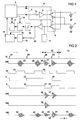
- An ultrasonic flow meter based on the time difference principle works, according to Figure 1 at least two ultrasonic transducers 1 and 2. These will controlled by a microcontroller 3, which two Outputs control signals 4 and 5 via a commutator 6 two switches 7 and 8 either with a transmit or one Receive circuit connected.
- the switch 7 is placed as shown, the switch 8, however, in the reverse position, so that the ultrasonic transducer 1 with the transmission circuit and Ultrasonic transducer 2 is connected to the receiving circuit.
- the ultrasound transducer is used for a runtime measurement downstream 2 with the transmission circuit and the ultrasonic transducer 1 connected to the receiving circuit.
- a transmission circuit 1 shows an amplifier 9, which from the microcontroller 3 a transmission pulse on a control signal 10 receives.
- the receiving circuit is made up of a receiving amplifier 11, a level limiting circuit 12, a Demodulator 13, a circuit for envelope evaluation 14, a receiving comparator 15, a gate circuit 16 and one Counter 17 formed.
- the level limiting circuit 12 is used for this purpose, the diodes, for example, connected in anti-parallel contains. This circuit is ineffective in normal measuring operation, because in this case the response threshold is significantly higher than the amplitude of the received signal.
- the transmit energy in diagnostic mode can also be reduced the transmit pulse width or the amplitude of the transmit pulse be reduced.
- the variation of the transmission pulse width is very easy to implement, for example by programming the Microcontrollers 3. It also has the advantage that the Decay behavior of the ultrasonic transducer 1 or 2 for different suggestions can be evaluated. To this Way is additional information about the state of the Transducer derivable.
- the microcontroller 3 puts through Control signal 19 fixed the measurement window by the gate circuit 16 is enabled by this control signal. So get there only within the measuring window pulses from the output of the Receive comparator 15 to the counter 17. Through the measurement window is also the envelope evaluation 14 for determination of a waveform parameter that it sends to the Microcontroller 3 passes. This waveform parameter will in the microcontroller 3 for self-test in the operating mode "Diagnosis" evaluated.
- the microcontroller 3 checks the Waveform parameters for compliance with an error criterion. If there is an error, it generates an error message, the to display the error to a not shown in Figure 1 higher-level control unit is output.
- the type of Error criteria and the structure of the error message are also like the entire process of the measurement and diagnosis procedure the programming of the microcontroller 3 fixed.
- the reception signal is an exception 18, depending on the condition of the ultrasonic flow meter in Figure 2, reference numerals 18A, 18B, 18C and 18D are used will.
- Runtime difference measurement is now done by changing the level of the two control signals 4 and 5 with edges 23 and 24 and a measurement is initiated upstream by outputting a pulse 25.
- the ultrasonic pulse arrives at the ultrasonic transducer 2 appears in a similar way to the Measurement downstream of a group 26 rising and falling again Vibrations, based on which the running time of the Ultrasonic pulse is determined upstream. From the difference The running times downstream and upstream can depend on the flow rate a medium in a measuring tube, on which the two ultrasonic transducers 1 and 2 are attached, closed will.
- the operating mode of the Ultrasonic flow meter from "Measure” shown in Figure 2 during periods T1 and T3 is set to one Operating mode "diagnosis", in Figure 2 during a period T2, switched.
- the self-test is initiated of the ultrasonic transducer 1 by a negative edge 27 of the Control signal 5, according to which the ultrasonic transducer 1 both with the transmission circuit as well as with the reception circuit is connected, and a pulse 28 on the control signal 10, through which the ultrasonic transducer 1 is excited to vibrate becomes.
- a pulse 28 on the control signal 10 through which the ultrasonic transducer 1 is excited to vibrate becomes.
- the end of the transmission process is indicated by a positive edge 29 of the control signal 19 opens a measurement window.
- the operating mode is activated again "Measure” switched and entered the time period T3.
- the time courses of the signals during the time period T3 again correspond to those of the period T1, the were also recorded during the "Measure" mode.
- the curve 18B of the received signal shows the error case that both ultrasonic transducers 1 and 2 are in order, the measuring section but is disturbed. This will reach the downstream and upstream ultrasound pulses not the respective Receive converter and it appear in during measurement operation the sections T1 and T3 no vibration groups as a received signal.
- a deviating can occur on the course 18D of the received signal 18 Behavior of the two ultrasonic transducers 1 and 2 determined will.
- the "Measure” mode in the time periods T1 and T3 continue to be vibration groups 39, 40 and 41 received, but their amplitudes are lower than in undisturbed operation.
- the "Diagnostics” mode the The cause of this can be determined.
- the amplitude of the Sending process following oscillation of the ultrasound transducer 1 has decreased significantly and will therefore become one Vibration group 42 recorded, the envelope 43 very is much flatter than an envelope 44 one at Self test of the ultrasonic transducer 2 recorded vibration group 45.
- a comparative assessment of the vibration groups 42 and 45 can be used for early damage detection be used. Also statements about measurement reliability or Limitations of the measuring accuracy can be derived from this. At a corresponding error signal will result in inadmissible deviations generated.
- a simplest test is too check whether the receiving comparator 15 ( Figure 1) during the Measurement window responds.
- Another possibility for evaluation is that the beginning of the measuring window is varied in succession so that by the receiving comparator 15 the next following Signal vibration is detected.
- the preferred time is of the signal zero crossing measured.
- the so determined Times are saved and the difference at the time of each previous signal zero crossing is calculated.
- From simple frequency monitoring is possible in this way. From the measured natural frequency of an ultrasonic transducer statements about his condition can be derived. In addition, this procedure can reduce the overall cooldown until a predefined level is undershot be measured.
- vibration groups obtained in the "Diagnostics" operating mode measurement, storage and evaluation of selected waveform parameters, e.g. B. amplitude, integral Energy content or decay gradient of the envelope.
- selected waveform parameters e.g. B. amplitude, integral Energy content or decay gradient of the envelope.
- the vibration groups are only within the Measuring window evaluated. You can use these waveform parameters with reference values previously stored in the microcontroller 3 or with values determined from the past for determination of impermissible deviations or changes be compared.
Landscapes
- Physics & Mathematics (AREA)
- General Physics & Mathematics (AREA)
- Engineering & Computer Science (AREA)
- Fluid Mechanics (AREA)
- Computer Networks & Wireless Communication (AREA)
- Radar, Positioning & Navigation (AREA)
- Remote Sensing (AREA)
- Electromagnetism (AREA)
- Measuring Volume Flow (AREA)
Applications Claiming Priority (2)
| Application Number | Priority Date | Filing Date | Title |
|---|---|---|---|
| DE19625667 | 1996-06-26 | ||
| DE19625667A DE19625667A1 (de) | 1996-06-26 | 1996-06-26 | Verfahren zum Selbsttest einer Einrichtung zur Ultraschall-Laufzeitmessung sowie Einrichtung zur Durchführung des Verfahrens |
Publications (2)
| Publication Number | Publication Date |
|---|---|
| EP0816865A2 true EP0816865A2 (fr) | 1998-01-07 |
| EP0816865A3 EP0816865A3 (fr) | 1999-03-03 |
Family
ID=7798126
Family Applications (1)
| Application Number | Title | Priority Date | Filing Date |
|---|---|---|---|
| EP97109967A Withdrawn EP0816865A3 (fr) | 1996-06-26 | 1997-06-18 | Procédé d'auto-test pour un système de mesure du délai de propagation à ultra-sons, et appareil pour ceci |
Country Status (2)
| Country | Link |
|---|---|
| EP (1) | EP0816865A3 (fr) |
| DE (1) | DE19625667A1 (fr) |
Cited By (5)
| Publication number | Priority date | Publication date | Assignee | Title |
|---|---|---|---|---|
| DE102012220311A1 (de) | 2012-11-08 | 2014-05-08 | Robert Bosch Gmbh | Verfahren zur Detektion der Sensordegradation bei Abstandssensoren |
| CN107131918A (zh) * | 2017-07-02 | 2017-09-05 | 中国计量大学 | 一种低功耗超声波流量计回波信号处理方法及电路 |
| CN111684242A (zh) * | 2018-02-02 | 2020-09-18 | 恩德莱斯和豪瑟尔欧洲两合公司 | 检测基于fmcw的液位测量装置的潜在故障状态的方法 |
| CN113671215A (zh) * | 2021-07-30 | 2021-11-19 | 苏州斯威高科信息技术有限公司 | 一种提高超声波风传感器精度的测量和校准方法及系统 |
| RU2806736C1 (ru) * | 2022-10-04 | 2023-11-03 | Общество с ограниченной ответственностью "Медуза" | Способ предотвращения повреждения акустического блока устройства для комплексной диагностики и терапии отраженным излучением HIFU |
Families Citing this family (17)
| Publication number | Priority date | Publication date | Assignee | Title |
|---|---|---|---|---|
| US6759644B2 (en) * | 2001-03-15 | 2004-07-06 | Omron Corporation | Sensor using radiation pulses |
| US6843110B2 (en) * | 2002-06-25 | 2005-01-18 | Fluid Components International Llc | Method and apparatus for validating the accuracy of a flowmeter |
| DE10247971A1 (de) * | 2002-10-15 | 2004-05-06 | Valeo Schalter Und Sensoren Gmbh | System zur Überwachung des Nahbereichs eines Kraftfahrzeuges mit Störungserkennung und Verfahren zur Ermittlung der Störungsfreiheit eines derartigen Systems |
| DE10254053B4 (de) * | 2002-11-19 | 2016-12-22 | Endress + Hauser Flowtec Ag | Verfahren und Vorrichtung zur Bestimmung und/oder Überwachung eines Volumen- und/oder Massenstroms |
| DE102005024134A1 (de) * | 2005-05-23 | 2007-01-11 | Endress + Hauser Flowtec Ag | Verfahren zur Bestimmung und/oder Überwachung einer Prozessgröße |
| DE102005045485A1 (de) | 2005-09-22 | 2007-04-12 | Endress + Hauser Flowtec Ag | Verfahren zur System- und/oder Prozessüberwachung bei einem Ultraschall-Durchflussmessgerät |
| DE102005057973B4 (de) | 2005-12-05 | 2017-02-23 | Robert Bosch Gmbh | Verfahren zur Funktionsprüfung eines Ultraschallsensors und Abstandsmessvorrichtung |
| EP2411095B1 (fr) * | 2009-03-23 | 2015-09-02 | LipoSonix, Inc. | Procédé de détermination de fonctionnalité d'un dispositif de thérapie par ultrasons |
| EP2394749A1 (fr) * | 2010-06-07 | 2011-12-14 | ELMOS Semiconductor AG | Procédé de reconnaissance d'une impureté ou d'une autre perturbation de fonctionnement d'un capteur à ultrasons d'une aide au stationnement pour un véhicule automobile |
| DE102012104042B4 (de) * | 2012-05-09 | 2021-09-16 | Endress + Hauser Flowtec Ag | Verfahren zur Überwachung des Betriebszustandes eines Ultraschallwandlers in einem Ultraschall-Durchflussmessgerät |
| DE102013100670B4 (de) | 2013-01-23 | 2022-09-29 | Endress + Hauser Flowtec Ag | Ultraschall-Durchflußmeßgerät mit Temperaturkompensation |
| DE102013222860A1 (de) * | 2013-11-11 | 2015-05-13 | Robert Bosch Gmbh | Verfahren zum Erfassen eines Fahrzeugumfeldes |
| DE102015107753A1 (de) * | 2015-05-18 | 2016-11-24 | Endress + Hauser Flowtec Ag | Verfahren zur Ermittlung einer charakteristischen Größe zur Bewertung einer Messanordnung umfassend ein Clamp-On-Ultraschall- Durchflussmessgerät und ein Rohr und/oder zur Bewertung des Messbetriebs dieser Messanordnung |
| DE102016119180A1 (de) | 2016-10-10 | 2018-04-12 | Endress + Hauser Flowtec Ag | Gehäuse für ein Feldgerät der Mess- und Automatisierungstechnik zur Überwachung und/oder Bestimmung mindestens einer Prozessgröße eines Mediums |
| US20200166640A1 (en) | 2017-08-09 | 2020-05-28 | Elmos Semiconductor Aktiengesellschaft | Self-testing measuring system |
| EP3480621B1 (fr) * | 2017-11-01 | 2022-05-11 | Samsung Medison Co., Ltd. | Appareil à ultrasons et son procédé de commande |
| DE102020002048A1 (de) | 2020-03-31 | 2021-09-30 | Diehl Metering Gmbh | Messeinrichtung zur Ermittlung einer Fluidgröße und Verfahren zur Überwachung des Betriebs einer Messeinrichtung |
Family Cites Families (9)
| Publication number | Priority date | Publication date | Assignee | Title |
|---|---|---|---|---|
| US4372166A (en) * | 1981-01-13 | 1983-02-08 | The Perkin-Elmer Corporation | Flowmeter system with digital phase shifter and calibration |
| JPS6073385A (ja) * | 1983-09-29 | 1985-04-25 | Mitsubishi Electric Corp | 超音波式障害物検知装置の故障検出回路 |
| DD233360A1 (de) * | 1984-12-28 | 1986-02-26 | Fortschritt Veb K | Einrichtung zur ueberwachung der funktion eines ultraschall-echolotes |
| US4762012A (en) * | 1987-01-29 | 1988-08-09 | Manning Technologies, Inc. | Universal upstream-downstream flowmeter tester |
| US4938054A (en) * | 1989-05-03 | 1990-07-03 | Gilbarco Inc. | Ultrasonic linear meter sensor for positive displacement meter |
| US5053747A (en) * | 1989-09-05 | 1991-10-01 | Pacesetter Infusion, Inc. | Ultrasonic air-in-line detector self-test technique |
| US4989446A (en) * | 1990-01-23 | 1991-02-05 | Dynatek Laboratories, Inc. | Ultrasound calibrator |
| DE4420329C1 (de) * | 1994-06-10 | 1995-10-26 | Hydrometer Gmbh | Verfahren zur Ultraschall-Messung von Durchflußmengen von strömenden Fluiden |
| DE4421692A1 (de) * | 1994-06-21 | 1996-01-04 | Christof Dipl Phys Ing Salz | Präzisions Durchflusszähler |
-
1996
- 1996-06-26 DE DE19625667A patent/DE19625667A1/de not_active Withdrawn
-
1997
- 1997-06-18 EP EP97109967A patent/EP0816865A3/fr not_active Withdrawn
Cited By (12)
| Publication number | Priority date | Publication date | Assignee | Title |
|---|---|---|---|---|
| DE102012220311A1 (de) | 2012-11-08 | 2014-05-08 | Robert Bosch Gmbh | Verfahren zur Detektion der Sensordegradation bei Abstandssensoren |
| WO2014072118A1 (fr) | 2012-11-08 | 2014-05-15 | Robert Bosch Gmbh | Procédés de détection de la dégradation de capteurs de distance |
| US9684068B2 (en) | 2012-11-08 | 2017-06-20 | Robert Bosch Gmbh | Methods for detecting sensor degradation in distance sensors |
| DE102012220311B4 (de) | 2012-11-08 | 2023-03-30 | Robert Bosch Gmbh | Verfahren zur Detektion der Sensordegradation bei Abstandssensoren |
| CN107131918A (zh) * | 2017-07-02 | 2017-09-05 | 中国计量大学 | 一种低功耗超声波流量计回波信号处理方法及电路 |
| CN107131918B (zh) * | 2017-07-02 | 2023-09-12 | 中国计量大学 | 一种低功耗超声波流量计回波信号处理方法及电路 |
| CN111684242A (zh) * | 2018-02-02 | 2020-09-18 | 恩德莱斯和豪瑟尔欧洲两合公司 | 检测基于fmcw的液位测量装置的潜在故障状态的方法 |
| CN111684242B (zh) * | 2018-02-02 | 2022-10-21 | 恩德莱斯和豪瑟尔欧洲两合公司 | 检测基于fmcw的液位测量装置的潜在故障状态的方法 |
| US11650302B2 (en) | 2018-02-02 | 2023-05-16 | Endress+Hauser SE+Co. KG | Method for detecting potential faulty states on an FMCW-based filling level measuring apparatus |
| CN113671215A (zh) * | 2021-07-30 | 2021-11-19 | 苏州斯威高科信息技术有限公司 | 一种提高超声波风传感器精度的测量和校准方法及系统 |
| CN113671215B (zh) * | 2021-07-30 | 2024-02-20 | 苏州斯威高科信息技术有限公司 | 一种提高超声波风传感器精度的测量和校准方法及系统 |
| RU2806736C1 (ru) * | 2022-10-04 | 2023-11-03 | Общество с ограниченной ответственностью "Медуза" | Способ предотвращения повреждения акустического блока устройства для комплексной диагностики и терапии отраженным излучением HIFU |
Also Published As
| Publication number | Publication date |
|---|---|
| EP0816865A3 (fr) | 1999-03-03 |
| DE19625667A1 (de) | 1998-01-02 |
Similar Documents
| Publication | Publication Date | Title |
|---|---|---|
| EP0816865A2 (fr) | Procédé d'auto-test pour un système de mesure du délai de propagation à ultra-sons, et appareil pour ceci | |
| EP0690976B1 (fr) | Procede et systeme permettant de constater et/ou de controler un niveau de remplissage predetermine d'un reservoir | |
| EP0452531B1 (fr) | Dispositif électrique pour mesurer le temps de propagation d'un signal électrique | |
| DE10254053B4 (de) | Verfahren und Vorrichtung zur Bestimmung und/oder Überwachung eines Volumen- und/oder Massenstroms | |
| DE2753472A1 (de) | Verfahren zur automatischen eigenueberwachung von zerstoerungsfreien pruefanlagen | |
| DE69933910T2 (de) | Nullspannungsübergangsdetektor sowie Verfahren zur Bestimmung des Nullspannungsübergangspunktes | |
| DE202011005427U1 (de) | Vorrichtung zum Messen der Laufzeit eines Ultraschallsignals in einer strömenden Flüssigkeit | |
| DE19939391C2 (de) | Vorrichtung zum Messen einer Strömungsgeschwindigkeit mit Ultraschall | |
| DE2636856A1 (de) | Verfahren und vorrichtung zur zerstoerungsfreien bewertung von klebverbindungen in realzeit | |
| DE19841154C2 (de) | Verfahren und Vorrichtung zur Messung der Laufzeit von Schallwellen | |
| EP0358887B1 (fr) | Circuit de détection d'erreur dans un appareil de mesure | |
| EP0762086B1 (fr) | Procédé pour la mesure par ultrasons du débit des fluides en écoulement | |
| WO2021069192A1 (fr) | Procédé de surveillance d'un système de dispositif de mesure | |
| DE1905213A1 (de) | Verfahren und Einrichtung zur Fehlerpruefung von Rohren mittels Ultraschall | |
| EP0773431A2 (fr) | Débitmètre ultrasonique pour des milieux liquides ou gazeux | |
| DE19522697A1 (de) | Verfahren und Schaltungsanordnung zur Messung der Strömungsgeschwindigkeit mittels akustischer Laufzeitdifferenzen | |
| DE102016114647A1 (de) | Verfahren zum Betreiben eines Messgeräts und Messgerät | |
| DE19602810A1 (de) | Verfahren und Einrichtung zur Laufzeitmessung eines elektrischen, elektromagnetischen oder akustischen Signals | |
| DE4114233C2 (de) | Anordnung zur Ultraschall-Durchflußmessung | |
| EP0072770B1 (fr) | Procédé et dispositif pour la mesure des différences du temps de transit des impulsions ultrasonores pour la détermination des champs d'écoulement | |
| EP0855577A1 (fr) | Procédé pour mettre au point des paramètres autonomy d'un mètre ultrasonore | |
| DE10106308C1 (de) | Verfahren und Einrichtung zur Messung der Laufzeit eines akustischen Signals | |
| EP0025026B1 (fr) | Dispositif pour la mesure de la vitesse d'un fluide | |
| DE102004027958B4 (de) | Verfahren und Vorrichtung zum Messen der Strömungsgeschwindigkeit von Fluiden | |
| DE2532889C2 (de) | Gerät zum Messen der Geschwindigkeit oder einer Geschwindigkeitskomponente der Strömung eines Strömungsmittels |
Legal Events
| Date | Code | Title | Description |
|---|---|---|---|
| PUAI | Public reference made under article 153(3) epc to a published international application that has entered the european phase |
Free format text: ORIGINAL CODE: 0009012 |
|
| AK | Designated contracting states |
Kind code of ref document: A2 Designated state(s): AT BE CH DE DK ES FI FR GB GR IE IT LI LU MC NL PT SE |
|
| PUAL | Search report despatched |
Free format text: ORIGINAL CODE: 0009013 |
|
| AK | Designated contracting states |
Kind code of ref document: A3 Designated state(s): AT BE CH DE DK ES FI FR GB GR IE IT LI LU MC NL PT SE |
|
| AKX | Designation fees paid | ||
| STAA | Information on the status of an ep patent application or granted ep patent |
Free format text: STATUS: THE APPLICATION IS DEEMED TO BE WITHDRAWN |
|
| 18D | Application deemed to be withdrawn |
Effective date: 20010101 |
|
| REG | Reference to a national code |
Ref country code: DE Ref legal event code: 8566 |