EP0816927B1 - Elément photosensible électrophotographique, ainsi que l'appareil et la cartouche de traitement le comprenant - Google Patents
Elément photosensible électrophotographique, ainsi que l'appareil et la cartouche de traitement le comprenant Download PDFInfo
- Publication number
- EP0816927B1 EP0816927B1 EP97401574A EP97401574A EP0816927B1 EP 0816927 B1 EP0816927 B1 EP 0816927B1 EP 97401574 A EP97401574 A EP 97401574A EP 97401574 A EP97401574 A EP 97401574A EP 0816927 B1 EP0816927 B1 EP 0816927B1
- Authority
- EP
- European Patent Office
- Prior art keywords
- substituted
- unsubstituted
- hydrogen
- photosensitive member
- same
- Prior art date
- Legal status (The legal status is an assumption and is not a legal conclusion. Google has not performed a legal analysis and makes no representation as to the accuracy of the status listed.)
- Expired - Lifetime
Links
Images

Classifications
-
- G—PHYSICS
- G03—PHOTOGRAPHY; CINEMATOGRAPHY; ANALOGOUS TECHNIQUES USING WAVES OTHER THAN OPTICAL WAVES; ELECTROGRAPHY; HOLOGRAPHY
- G03G—ELECTROGRAPHY; ELECTROPHOTOGRAPHY; MAGNETOGRAPHY
- G03G5/00—Recording-members for original recording by exposure, e.g. to light, to heat or to electrons; Manufacture thereof; Selection of materials therefor
- G03G5/14—Inert intermediate or cover layers for charge-receiving layers
- G03G5/147—Cover layers
- G03G5/14708—Cover layers comprising organic material
- G03G5/14713—Macromolecular material
- G03G5/14747—Macromolecular material obtained otherwise than by reactions only involving carbon-to-carbon unsaturated bonds
- G03G5/14773—Polycondensates comprising silicon atoms in the main chain
-
- G—PHYSICS
- G03—PHOTOGRAPHY; CINEMATOGRAPHY; ANALOGOUS TECHNIQUES USING WAVES OTHER THAN OPTICAL WAVES; ELECTROGRAPHY; HOLOGRAPHY
- G03G—ELECTROGRAPHY; ELECTROPHOTOGRAPHY; MAGNETOGRAPHY
- G03G5/00—Recording-members for original recording by exposure, e.g. to light, to heat or to electrons; Manufacture thereof; Selection of materials therefor
- G03G5/14—Inert intermediate or cover layers for charge-receiving layers
- G03G5/147—Cover layers
- G03G5/14708—Cover layers comprising organic material
- G03G5/14713—Macromolecular material
- G03G5/14747—Macromolecular material obtained otherwise than by reactions only involving carbon-to-carbon unsaturated bonds
- G03G5/14756—Polycarbonates
Definitions
- the present invention relates to electrophotographic photosensitive members, process cartridges and electrophotographic apparatuses.
- the present invention relates to an electrophotographic photosensitive member, a process cartridge and electrophotographic apparatus provided with a photosensitive layer containing a specified resin.
- U.S. Patent No. 3,837,851 discloses a photosensitive member having a charge transfer layer containing triallylpyrazoline
- U.S. Patent No. 3,871,880 discloses a photosensitive member comprising a charge generating layer containing a perylene pigment derivative and a charge transfer layer containing a condensation product of 3-propylene and formaldehyde.
- Organic photoconductive materials are sensitive to their characteristic wavelength ranges.
- Japanese Unexamined Patent Publication Nos. 61-272754 and 56-167759 disclose compounds highly sensitive to visible light
- Japanese Unexamined Patent Publication Nos. 57-19576 and 61-228453 disclose compounds highly sensitive to an infrared region.
- compounds highly sensitive to an infrared region have been increasingly used in laser beam printers (hereinafter referred to as LBP) and LED printers.
- electrophotographic photosensitive members must be provided with sensitivity, electrical characteristics, mechanical properties and optical characteristics suitable for the electrophotographic processes employed.
- electrophotographic photosensitive members must be durable against repeated electrical and mechanical forces, such as charging, exposure, development, transfer and cleaning, directly applied to their surfaces. In particular, they must have high electric and mechanical resistance to deterioration due to ozone and nitrogen oxides forming during charging, and surface abrasion occurring during discharging and cleaning.
- Another problem to be solved is a phenomenon called "photomemory" in which a residual carrier on the light irradiated section forms a potential difference with the non-light irradiated section.
- Contact charging processes in which a charging member comes in contact with an electrophotographic photosensitive member and the electrophotographic photosensitive member is charged by applying a voltage to the charging member, have been increasingly employed, as disclosed in Japanese Unexamined Patent Publication Nos. 57-17826 and 58-40566, and cause new problems.
- Contact charging processes have some technical and economical advantages as compared to scorotrons; for example, extremely low ozone formation, and low electricity consumption (in scorotrons, approximately 80% of current applied to a wire of the charger flows to a shield of the charger).
- the electrophotographic photosensitive member in accordance with the present invention comprises a substrate and a photosensitive layer formed thereon, a surface layer of the photosensitive layer containing at least one resin selected from the group consisting of (a) a polyarylate resin having a structural unit represented by the following general formula (1) and (b) a polycarbonate resin having a structural unit represented by the following general formula (2): wherein, X 1 and X 2 are each single bond, -O-, -S- or substituted or unsubstituted alkylene and are the same or different, R 1 to R 8 and R 11 to R 14 are each hydrogen, halogen, or substituted or unsubstituted alkyl or substituted or unsubstituted aryl and are the same or different, and R 9 and R 10 are each hydrogen, halogen, or substituted or unsubstituted silyl, substituted or unsubstituted alkyl or substituted or unsubstituted aryl and are the same or different, and n is
- a process cartridge and an electrophotographic photosensitive member include the electrophotographic apparatus set forth above.
- the electrophotographic photosensitive member in accordance with the present invention comprises a substrate and a photosensitive layer formed thereon.
- a surface layer encompasses the photosensitive layer by itself, where the photosensitive layer is a single layer and also includes the outer layer of the photosensitive layer, when the photosensitive layer is a structure formed by laminating together a plurality of layers.
- a surface layer of the photosensitive layer contains at least one resin selected from the group consisting of (a) a polyarylate resin having a structural unit represented by the following general formula (1) and (b) a polycarbonate resin having a structural unit represented by the following general formula (2): wherein, X 1 and X 2 are each single bond, -O-, -S- or substituted or unsubstituted alkylene and are the same or different, R 1 to R 8 and R 11 to R 14 are each hydrogen, halogen, or substituted or unsubstituted alkyl or substituted or unsubstituted aryl and are the same or different, and R 9 and R 10 are each hydrogen, halogen, or substituted or unsubstituted silyl, substituted or unsubstituted alkyl or substituted or unsubstituted aryl and are the same or different, and n is an integer of 2 or more; wherein X 3 and X 4 are each single bond, -O-, -S-
- the alkylene groups in the general formulae (1) and (2) are preferably methylene, ethylene, and i-propylene.
- the halogen atoms include fluorine, chlorine, and bromine.
- the alkyl groups are preferably lower alkyl and cycloalkyl, such as methyl, ethyl, propyl, and cyclohexyl.
- the aryl groups are preferably phenyl, naphthyl and anthryl.
- the substituents for the groups set forth above include halogen, such as fluorine, chlorine and bromine; alkyl, such as methyl, ethyl and propyl; aryl, such as phenyl, naphthyl and anthryl; aralkyl, such as benzyl and phenethyl; and alkoxy, such as methoxy, ethoxy and propoxy.
- halogen such as fluorine, chlorine and bromine
- alkyl such as methyl, ethyl and propyl
- aryl such as phenyl, naphthyl and anthryl
- aralkyl such as benzyl and phenethyl
- alkoxy such as methoxy, ethoxy and propoxy.
- R 9 , R 10 , R 23 and R 24 may be present in combinations of two or more types in the molecule. In other words, two or more types of may be present in the molecule.
- Suffixes n and m in the general formulae (1) and (2) are each an integer of 2 or more. These suffixes are preferably 50 or less in view of satisfactory flexibility, and more preferably 20 or less.
- the weight average molecular weight of the polyarylate resin used in the present invention preferably ranges from 50,000 to 300,000, and more preferably from 60,000 to 150,000.
- the weight average molecular weight of the polycarbonate resin used in the present invention preferably ranges from 30,000 to 300,000, and more preferably from 40,000 to 80,000.
- the weight average molecular weight is derived by gel permeation chromatography.
- the polyarylate resin having a structural unit represented by the general formula (1) can be prepared by interfacial polymerization of bisphenol represented by the following general formula (3) in the presence of a chloride of an aromatic dicarboxylic acid and an alkali in a nonaqueous solvent/water system: wherein X 1 , X 2 , R 1 to R 10 and n are the same as in the formula (1).
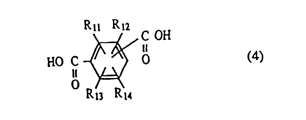
- the aromatic dicarboxylic acid preferably has the following general formula (4): wherein R 11 and R 14 are the same as in the general formula (1).
- the ratio of one chloride to the other chloride in the mixture is determined in view of solubility of the resulting resin, and preferably is 1/1 in ordinary reaction systems, because the solubility of the resin may greatly decrease when either chloride is not greater than 30 mol% of the total amount of chloride.
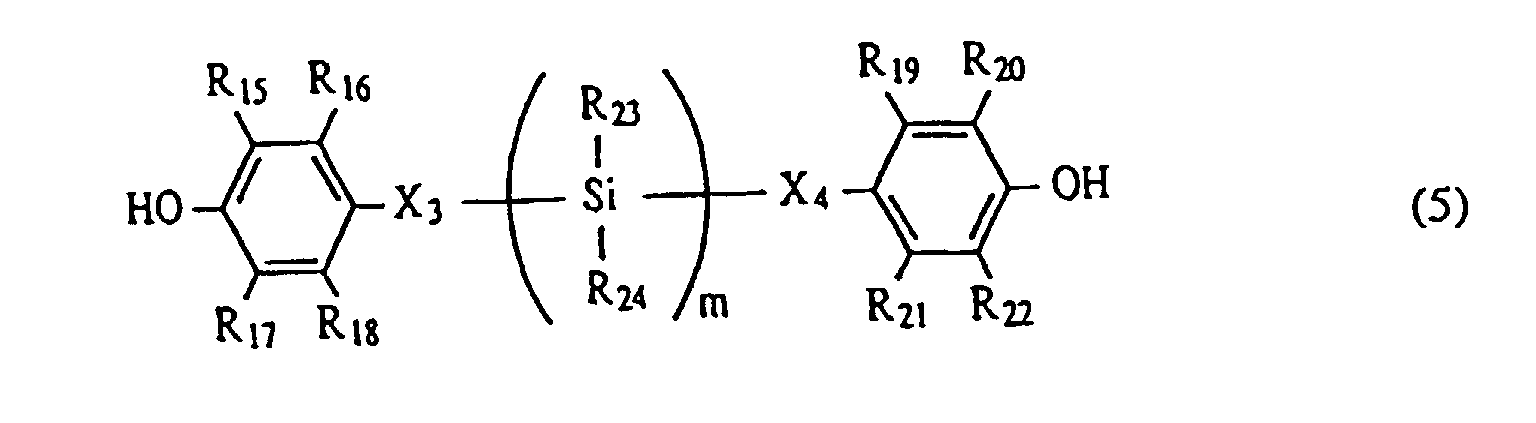
- the polycarbonate resin having a structural unit represented by the general formula (2) can be prepared by polymerization of bisphenol represented by the following general formula (5) in the presence of phosgene: wherein X 3 , X 4 , R 15 to R 24 , and m are the same as in the general formula (1).
- Examples of preferred aromatic dicarboxylic acids represented by the general formula (4) are as follows, but are not limited to:
- the above-mentioned bisphenols may be used alone or in combination.
- the above-mentioned bisphenols be copolymerized with a bisphenol represented by the following general formula (6) in order to enhance flexibility of the resulting resin: wherein X 5 is single bond, -O-, -S-, or substituted or unsubstituted alkylidene or substituted or unsubstituted cycloalkylidene, and R 25 to R 32 are each hydrogen, halogen, substituted or unsubstituted alkyl or substituted or unsubstituted aryl and are the same or different.
- the halogen atoms represented in the general formula (6) include fluorine, chlorine and bromine.
- the alkyl groups are preferably methyl, ethyl and propyl.
- the alkylidenes are preferably ethylidene and isopropylidene.
- the cycloalkylidenes are preferably cyclopentylidene and cyclohexylidene.
- the aryl groups are preferably phenyl, naphthyl and anthryl.
- the substituents for the groups described above include halogen, alkyl and aryl.
- bisphenols represented by the general formula (6) include bisphenol Z (X 5 is cyclohexylidene and R 25 to R 32 are hydrogen), bisphenol A (X 5 is isopropylidene and R 25 to R 32 are hydrogen), bisphenol C (X 5 is isopropylidene, R 25 to R 32 are methyl, and R 26 to R 31 are hydrogen) and bisphenol AF (X 5 is hexafluoroisopropylidene and R 25 to R 32 are hydrogen).
- bisphenol Z, bisphenol A and bisphenol C are more preferably used.
- a bisphenol represented by the general formula (3) or (4) be 1 to 80 mol%, and more preferably 1 to 40 mol% of the total amount of bisphenol.
- a ratio may change with the structure of the bisphenol employed.
- polyarylate resins having structural units represented by the general formula (1) and polycarbonate resins having structural units represented by the general formula (2) can be used as a blend. Further, resins having other structural units not represented by the general formulae (1) and (2) can be blended within a range achieving the advantages of the present invention.
- the electrophotographic photosensitive member in accordance with the present invention exhibits particularly high solvent crack resistance, high mechanical strength, low photomemory characteristics and high electrical durability to AC charge.
- the polyarylate resin and the polycarbonate resin used in the present invention contain stiffness segments in their structural units, and it is considered that durability of the polymer coating film of the electrophotographic photosensitive member is improved by partial vitrification of these segments during formation of the electrophotographic photosensitive member.
- Polymeric resins essentially consisting of silylene bonds also do not deteriorate in direct charge, but are mechanically considerably brittle due to high vitrification characteristics of the film.
- the surface layer of the electrophotographic photosensitive member in accordance with the present invention represents the photosensitive layer itself.
- This embodiment is illustrated in Fig. 2, wherein a single photosensitive layer 13 is formed on substrate 14.
- the surface layer represents the charge transfer layer.
- This laminated structure embodiment is illustrated in Figure 3 in which a photosensitive layer 15 contains an outer charge transfer layer 16 and a charge generating layer 17, which, in turn, is laminated to a substrate 18.
- a laminated structure is preferable in view of electrophotographic characteristics.
- the charge transfer layer can be formed by applying a solution, in which the resin set forth above as a binder, a charge transfer material are dissolved in an appropriate solvent, to a substrate, followed by drying.
- a solution in which the resin set forth above as a binder, a charge transfer material are dissolved in an appropriate solvent
- Examples of usable charge transfer materials include triarylamine compounds, hydrazone compounds, stilbene compound, pyrazoline compound, oxazole compounds, triallylmethane compounds and thiazole compounds.
- the ratio of the charge transfer material and the binder preferably ranges from 1:0.5 to 1:2 by weight.
- the thickness of the charge transfer layer preferably ranges from 5 ⁇ m to 40 ⁇ m, and more preferably 15 ⁇ m to 30 ⁇ m.
- the charge generating layer can be formed by applying and drying a dispersion containing a charge generating material, a binder and a solvent, in which the amount of the binder resin is 0.3 to 4 times the charge generating material.
- the dispersion is prepared by dispersing the charge generating material and the binder in the solvent with a homogenizer, an ultrasonic dispersion machine, a ball mill, a vibrational ball mill, a sand mill, an attritor, a roll mill or a liquid collision type high speed dispersion machine.
- Examples of charge generating materials used in the present invention include dyes, such as selenium-tellurium dyes, pyrylium dyes and thiapyrylium dyes; and pigments, such as phthalocyanine pigments, anthanthrone pigments, dibenzopyrenequinone pigments, trisazo pigments, cyanine pigments, disazo pigments, monoazo pigments, indigo pigments, quinacridone pigments, and asymmetric quinocyanine pigments.
- the thickness of the charge transfer layer preferably is not more than 5 ⁇ m, and more preferably ranges from 0.1 to 2 ⁇ m.
- the layer can be formed by coating and drying a solution or dispersion containing the charge generating material and charge transfer material, as well as the above-mentioned resin.
- the thickness preferably ranges from 5 to 40 ⁇ m and more preferably from 15 to 30 ⁇ m.
- the surface layer in accordance with the present invention may contain an antioxidant and a lubricant.
- Materials for use in the substrates in accordance with the present invention include conductive materials.
- conductive materials include metals such as aluminum and stainless steel, metals, paper, and plastics provided with a conductive layer. These conductive materials may have a sheet or cylindrical shape.
- a conductive layer may be provided between the substrate and the photosensitive layer in order to prevent interference band formation or to cover flaws on the substrate.
- a conductive layer can be formed by applying and drying a dispersion containing a conductive powder, such as carbon black or a particulate metal oxide, and a binding resin.
- the thickness of the conductive layer preferably ranges from 5 ⁇ m to 40 ⁇ m, and more preferably from 10 to 30 ⁇ m.
- an interlayer having adhesiveness and barrier properties may be provided between the substrate and the photosensitive layer.
- the interlayer materials include polyamides, polyvinyl alcohol, polyethylene oxide, ethyl cellulose, casein, polyurethanes, and polyether urethanes. These materials may be applied as a solution in an appropriate solvent.
- the thickness of the interlayer preferably ranges from 0.05 ⁇ m to 5 ⁇ m, and more preferably 0.3 ⁇ m to 1 ⁇ m.
- Figure 1 is a schematic cross-sectional view of an electrophotographic apparatus provided with a process cartridge using an electrophotographic photosensitive member in accordance with the present invention.
- an electrophotographic photosensitive member 1 in accordance with the present invention rotates along an axis 2 in the direction as shown by the arrow at a predetermined speed.
- the peripheral surface of the photosensitive member 1 is uniformly charged at a given negative or positive potential with a primary charging means 3 during rotation, and is then subjected to image exposure 4 by an exposure means (not shown in the drawing), such as a slit exposure, or a laser beam scanning exposure.
- a latent image is continuously formed on the peripheral surface of the photosensitive member 1.
- the formed latent image is developed with a toner by a developing means 5 and the developed toner image is transferred to a recording material 7 by a transfer means 6.
- the recording material is fed from a feeding section (not shown in the drawing) to a space between the photosensitive member 1 and the transfer means 6 in synchronism with the rotation of the photosensitive member 1.
- the toner image is transferred to recording material 7 from the surface of the photosensitive member 1.
- the recording material 7 is separated from the photosensitive member surface and conducted to an image fixing means 8.
- the transferred image on the recording material 7 is fixed by the image fixing means 8.
- the recording material 7 containing the fixed toner image is passed out of the apparatus as a copy.
- the primary charging means 3 is a contact charging means using a charging roll or the like, the preliminary exposure light is not always necessary.
- a plurality of the components selected from the group consisting of the photosensitive member 1, the primary charging means 3, the developing means 5 and the cleaning means 9 are integrated in a process cartridge, which can be loaded to and unloaded from the main body of an electrophotographic apparatus, e.g. a copying machine or a laser beam printer.
- a process cartridge which can be loaded to and unloaded from the main body of an electrophotographic apparatus, e.g. a copying machine or a laser beam printer.
- at least one component of the primary charging means 3, the developing means 5 and the cleaning means 9 is integrated with the photosensitive member 1 in process cartridge 11, and process cartridge 11 is loaded to and unloaded from the main body of the apparatus using a guiding means, e.g. rails 12 in the main body.
- image exposure 4 represents reflected light or transmitted light from an original document, or light from a laser, LED or shutter array, driven by signals from the original document when the electrophotographic apparatus is a copying machine or a printer.
- Conductive pigment SnO 2 coated barium sulfate 10 pbw Pigment for adjusting resistance: titanium oxide 2 pbw Binder resin: phenol resin 6 pbw Leveling material: silicone oil 0.001 pbw Solvent: methanol/methoxypropanol (0.2/0.8) 20 pbw
- a solution composed of 3 pbw of N-methoxymethylated nylon, 3 pbw of copolymeric nylon and a solvent mixture of 65 pbw of methanol and 30 pbw of n-butanol was coated on the resulting conductive layer by a dip coating process, followed by drying.
- An interlayer having a thickness of 0.5 ⁇ m was formed.
- a dispersion was prepared by dispersing 4 pbw of oxytitanium phthalocyanine having strong X-ray (CuK ⁇ characteristic) diffraction peaks (2 ⁇ 0.2 degrees) at 9.0 degrees, 14.2 degrees, 23.9 degrees and 27.1 degrees and 2 pbw of polyvinyl butyral (Trade Name: S-LEC, made by Sekisui Chemical Co., Ltd.) into 60 pbw of cyclohexanone using a sand mill with 1-mm glass beads for 4 hours; and then adding 100 pbw of ethyl acetate.
- the dispersion was coated on the interlayer by a dip coating process, followed by drying. A charge generating layer having a thickness of 0.3 ⁇ m was formed.
- the resin was synthesized as follows: Bisphenol (0.002 mol) represented in Compound 1, bisphenol C (0.002 mol) and bisphenol Z (0.002 mol) were placed into a 1-liter mixer containing an aqueous solution in which sodium hydroxide (0.8 g) and tetramethylammonium chloride (1 g) were dissolved into 100 ml water. A solution formed of terephthalyl chloride (0.003 mol) and isophthalyl chloride (0.003 mol) dissolved in 1,2-dichloroethane (30 ml), was added to the mixer while stirring. The mixture was further stirred at high speed for 10 minutes after the addition, and allowed to stand for 2 hours, thereby forming a 1,2-dichloroethane layer.
- the 1,2-dichloroethane layer was recovered and a large amount of hexane was added to the 1,2-dichloroethane solution to precipitate the resulting resin.
- the resin was purified by dissolving into chloroform and then precipitating again with methanol. The final yield was 65%.
- the molecular weight was determined by gel permeation chromatography.
- the solution containing the charge transfer material and the resin was coated on the charge generating layer by a dip coating process and dried at 120 °C for 2 hours.
- a charge transfer layer having a thickness of 25 ⁇ m was formed.
- the electrophotographic photosensitive member was loaded in a modified LBP "Laser Writer 16/600PS" made by Apple (process speed: 98 mm/sec).
- the modification involves constant voltage control of primary charging instead of a constant current control.
- the electrophotographic photosensitive member was subjected to continuous paper feeding test with the modified apparatus at 28 °C and 90% RH.
- An image used in the test was an A4 size grid pattern with a printing rate of 4%.
- the operation was performed by an intermittent mode stop per print.
- the copying operation was continued until fogging occurred by visual observation, while supplying toner.
- the number of repeated copying cycles was recorded as durability.
- Taber abrasion of a fresh electrophotographic photosensitive member was determined by means of weight loss during an abrasion test fcr 25 minutes using an ABRASION TESTER made by Yasuda Seiki Seisakusho Co., Ltd. with an abrasion tape.
- a photomemory value was determined as follows: A section of a fresh electrophotographic photosensitive member was irradiated with light from a white fluorescent lighting of 3000 Lux for 20 minutes, allowed to stand for 15 minutes, and then subjected to light portion potential measurement. The photomemory value was defined as a difference in light portion potential between the light irradiated section and the non-light-irradiated section. The light portion potential was determined by measuring a surface potential when a solid black image was formed on the electrophotographic photosensitive member in the same LBP with a surface potentiometer.
- Solvent crack resistance was determined as follows: Finger grease was adhered to the surface of a fresh electrophotographic photosensitive member, allowed to stand for 48 hours, then solvent crack formation was observed by microscopy. These results are set forth in Table 1.
- a series of electrophotographic photosensitive members were prepared and evaluated as in Example 1, except that resins represented in Table 2 were used in charge transfer layers.
- Each resin was synthesized as follows: Bisphenol (0.033 mol) represented in Compound 1, bisphenol C (0.033 mol) and bisphenol Z (0.033 mol) were placed into a four neck flask, and 228 ml of pyridine was added. While stirring a gas inlet and a gas outlet were connected to the flask, and phosgene was fed into the flask through the gas inlet for 30 minutes at a rate of 0.25 g/min in a draft chamber. After gas introduction, the solution was further stirred for 20 minutes, and 250 ml of methanol was added over 5 minutes to precipitate the resulting resin. After collecting the precipitated resin, the resin was washed with 500 ml of methanol, and dried. Then, the resin was dissolved in 50 ml of chloroform and the solution was dropped into 1 liter of methanol, followed by filtration and drying. The final yield was 68%. The results are shown in Table 2.
- Electrophotographic photosensitive members were prepared and evaluated as in Example 1, except that the compounds described in Table 3 were used as resins for charge transfer layers.
- the Structural Units 1 through 5 in Table 3 have the following structures:
Landscapes
- Physics & Mathematics (AREA)
- Chemical & Material Sciences (AREA)
- Chemical Kinetics & Catalysis (AREA)
- Spectroscopy & Molecular Physics (AREA)
- General Physics & Mathematics (AREA)
- Photoreceptors In Electrophotography (AREA)
Claims (21)
- Elément photosensible électrophotographique comprenant : un substrat et une couche photosensible formée sur ce substrat, une couche de surface de la couche photosensible contenant au moins une résine choisie dans le groupe consistant en (a) une résine de polyarylate ayant un motif structural représenté par la formule générale (1) suivante, et (b) une résine de polycarbonate ayant un motif structural représenté par la formule générale (2) suivante :dans laquelle X1 et X2 représentent chacun une liaison simple, -O-, -S- ou un groupe alkylène substitué ou non substitué et sont identiques ou différents, R1 à R8 et R11 à R14 représentent chacun l'hydrogène, un halogène, ou un groupe alkyle substitué ou non substitué ou aryle substitué ou non substitué et sont identiques ou différents, et R9 et R10 représentent chacun l'hydrogène, un halogène ou un groupe silyle substitué ou non substitué, alkyle substitué ou non substitué ou aryle substitué ou non substitué et sont identiques ou différents, et n représente un nombre entier égal ou supérieur à 2 ;
 dans laquelle X3 et X4 représentent chacun une liaison simple, -O-, -S- ou un groupe alkylène substitué ou non substitué et sont identiques ou différents, R15 à R22 représentent chacun l'hydrogène, un halogène, un groupe alkyle substitué ou non substitué ou aryle substitué ou non substitué et sont identiques ou différents, R23 et R24 représentent chacun l'hydrogène, un halogène, un groupe silyle substitué ou non substitué, alkyle substitué ou non substitué ou aryle substitué ou non substitué et sont identiques ou différents, et m représente un nombre entier égal ou supérieur à 2.
- Elément photosensible électrophotographique suivant la revendication 1, dans lequel ladite résine d'au moins un type consiste en une résine de polyarylate.
- Elément photosensible électrophotographique suivant la revendication 1, dans lequel X1 et X2 représentent chacun une liaison simple, -O- ou un groupe éthylène non substitué, R1 à R8 représentent chacun l'hydrogène, R9 représente un groupe phényle, R10 représente un groupe méthyle et n est égal à 5 ou 7.
- Elément photosensible électrophotogrraphique suivant la revendication 2, dans lequel la résine de polyarylate comprend en outre le motif structural suivant :dans lequel X5 représente une liaison simple, -O-, -S- ou un groupe alkylidène substitué ou non substitué ou cycloalkylidène substitué ou non substitué, et R11 à R14 et R25 à R32 représentent chacun l'hydrogène, un halogène ou un groupe alkyle substitué ou non substitué ou aryle substitué ou non substitué.

- Elément photosensible électrophotographique suivant la revendication 4, dans lequel le motif structural comprend une association choisie dans le groupe consistant en (i) un groupe X5 consistant en un groupe isopropylidène et chacun des groupes R25 à R32 consistant en l'hydrogène ; (ii) un groupe X5 consistant en un groupe cyclohexylidène et chacun des groupes R25 à R32 consistant en l'hydrogène ; et (iii) un groupe X5 consistant en un groupe isopropylidène, chacun des groupes R25 et R32 consistant en un groupe méthyle et chacun des groupes R26 à R31 consistant en l'hydrogène.
- Elément photosensible électrophotographique suivant la revendication 2, dans lequel la résine de polyarylate est synthétisée à partir (i) d'un bisphénol représenté par la formule générale (3) suivante et (ii) d'un acide dicarboxylique aromatique :dans laquelle X1, X2, R1 à R10 et n répondent aux définitions mentionnées pour la formule générale (1).

- Elément photosensible électrophotographique suivant la revendication 6, dans lequel l'acide dicarboxylique aromatique est représenté par la formule générale (4) suivante :dans laquelle R11 à R14 répondent aux définitions mentionnées pour la formule générale (1).
- Elément photosensible électrophotographique suivant la revendication 1, dans lequel la résine d'au moins un type consiste en une résine de polycarbonate.
- Elément photosensible électrophotographique suivant la revendication 8, dans lequel X3 et X4 représentent chacun une liaison simple, -O- ou un groupe éthylène non substitué, R15 à R22 représentent chacun l'hydrogène, R23 représente un groupe phényle, R24 représente un groupe méthyle et m est égal à 5 ou 7.
- Elément photosensible électrophotographique suivant la revendication 8, dans lequel la résine de polycarbonate comprend en outre le motif structural suivant :dans lequel X5 représente une liaison simple, -O-, -S- ou un groupe alkylidène substitué ou non substitué ou cycloalkylidène substitué ou non substitué, et R25 à R32 représentent chacun l'hydrogène, un halogène ou un groupe alkyle substitué ou non substitué ou aryle substitué ou non substitué.
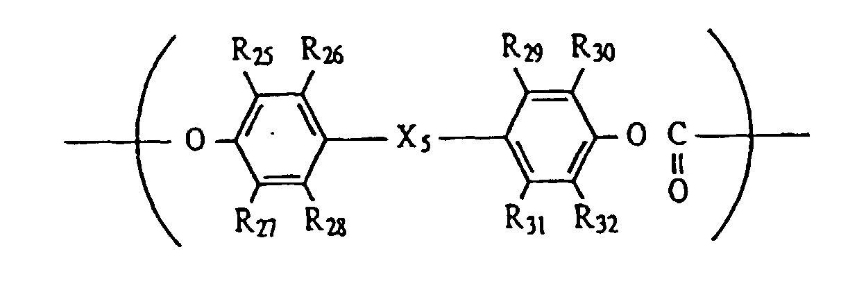
- Elément photosensible électrophotographique suivant la revendication 10, dans lequel le motif structural comprend une association choisie dans le groupe consistant en (i) un groupe X5 consistant en un groupe isopropylidène et chacun des groupes R25 à R32 consistant en l'hydrogène ; (ii) un groupe X5 consistant en un groupe cyclohexylidène et chacun des groupes R25 à R32 consistant en l'hydrogène ; et (iii) un groupe X5 consistant en un groupe isopropylidène, chacun des groupes R25 et R32 consistant en un groupe méthyle et chacun des groupes R26 à R31 consistant en l'hydrogène.
- Elément photosensible électrophotographique suivant la revendication 8, dans lequel la résine de polycarbonate est synthétisée à partir (i) d'un bisphénol représenté par la formule générale (5) suivante et (ii) du phosgène :formule dans laquelle X3, X4, R15 à R24 et m répondent aux définitions mentionnées pour la formule générale (2).
- Elément photosensible électrophotographique suivant la revendication 1, dans lequel la couche photosensible est un stratifié comprenant, dans cet ordre, une couche de production de charge et une couche de transfert de charge sur le substrat, et la résine est présente dans la couche de transfert de charge en tant que couche de surface.
- Cartouche de traitement, comprenant :
un élément photosensible électrophotographique et au moins un moyen choisi dans le groupe consistant en un moyen de charge, un moyen de développement et un moyen de nettoyage, ledit élément photosensible électrophotographique et ledit au moins un moyen étant portés de manière intégrée et étant amovibles d'un corps principal d'appareil électrophotographique, ledit élément photosensible électrophotographique comprenant : un substrat et une couche photosensible formée sur ce substrat, une couche de surface de la couche photosensible contenant au moins une résine choisie dans le groupe consistant en (a) une résine de polyarylate ayant un motif structural représenté par la formule générale (1) suivante et (b) une résine de polycarbonate ayant un motif structural représenté par la formule générale (2) suivante :dans laquelle X1 et X2 représentent chacun une liaison simple, -O-, -S- ou un groupe alkylène substitué ou non substitué et sont identiques ou différents, R1 à R8 et R11 à R14 représentent chacun l'hydrogène, un halogène ou un groupe alkyle substitué ou non substitué ou aryle substitué ou non substitué et sont identiques ou différents, et R9 et R10 représentent chacun l'hydrogène, un halogène ou un groupe silyle substitué ou non substitué, alkyle substitué ou non substitué ou aryle substitué ou non substitué et sont identiques ou différents, et n représente un nombre entier égal ou supérieur à 2 ;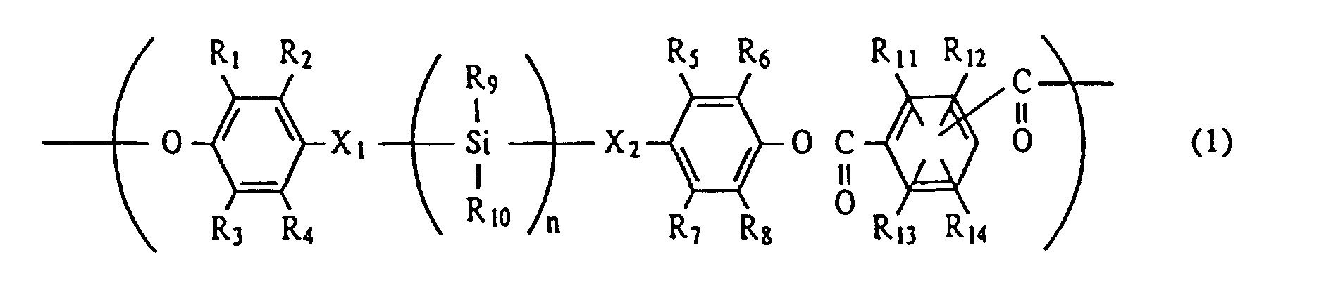 dans laquelle X3 et X4 représentent chacun une liaison simple, -O-, -S- ou un groupe alkylène substitué ou non substitué et sont identiques ou différents, R15 à R22 représentent chacun l'hydrogène, un halogène, un groupe alkyle substitué ou non substitué ou aryle substitué ou non substitué et sont identiques ou différents, R23 et R24 représentent chacun l'hydrogène, un halogène, un groupe silyle substitué ou non substitué, alkyle substitué ou non substitué ou aryle substitué ou non substitué et sont identiques ou différents, et m représente un nombre entier égal ou supérieur à 2.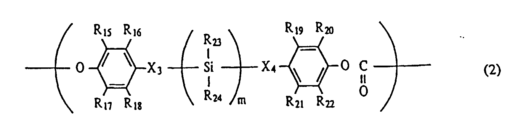
- Cartouche de traitement suivant la revendication 14, dans laquelle la résine d'au moins un type consiste en une résine de polyarylate.
- Cartouche de traitement suivant la revendication 14, dans laquelle la résine d'au moins un type consiste en une résine de polycarbonate.
- Cartouche de traitement suivant la revendication 14, dans laquelle le moyen de charge est un moyen de charge par contact.
- Appareil électrophotographique, comprenant : un élément photosensible électrophotographique, un moyen de charge, un moyen d'exposition, un moyen de développement et un moyen de nettoyage, ledit élément photosensible électrophotographique comprenant un substrat et une couche photosensible formée sur ce substrat, une couche de surface de la couche photosensible contenant au moins une résine choisie dans le groupe consistant en (a) une résine de polyarylate ayant un motif structural représenté par la formule générale (1) suivante et (b) une résine de polycarbonate ayant un motif structural représenté par la formule générale (2) suivante :dans laquelle X1 et X2 représentent chacun une liaison simple, -O-, -S- ou un groupe alkylène substitué ou non substitué et sont identiques ou différents, R1 à R8 et R11 à R14 représentent chacun l'hydrogène, un halogène ou un groupe alkyle substitué ou non substitué ou aryle substitué ou non substitué et sont identiques ou différents, et R9 et R10 représentent chacun l'hydrogène, un halogène ou un groupe silyle substitué ou non substitué, alkyle substitué ou non substitué ou aryle substitué ou non substitué et sont identiques ou différents, et n représente un nombre entier égal ou supérieur à 2 ;
 dans laquelle X3 et X4 représentent chacun une liaison simple, -O-, -S- ou un groupe alkylène substitué ou non substitué et sont identiques ou différents, R15 à R22 représentent chacun l'hydrogène, un halogène, un groupe alkyle substitué ou substitué ou non substitué ou aryle substitué ou non substitué et sont identiques ou différents, R23 et R24 représentent chacun l'hydrogène, un halogène, un groupe silyle substitué ou non substitué, alkyle substitué ou non substitué ou aryle substitué ou non substitué et sont identiques ou différents, et m représente un nombre entier égal ou supérieur à 2.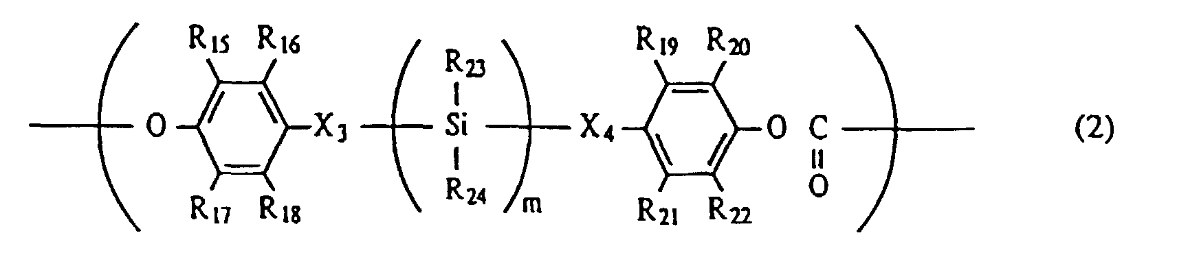
- Appareil électrophotographique suivant la revendication 18, dans lequel la résine d'au moins un type consiste en une résine de polyarylate.
- Appareil électrophotographique suivant la revendication 18, dans lequel la résine d'au moins un type consiste en une résine de polycarbonate.
- Appareil électrophotographique suivant la revendication 18, dans lequel le moyen de charge est un moyen de charge par contact.
Applications Claiming Priority (6)
| Application Number | Priority Date | Filing Date | Title |
|---|---|---|---|
| JP17513296 | 1996-07-04 | ||
| JP175132/96 | 1996-07-04 | ||
| JP17513696 | 1996-07-04 | ||
| JP17513296 | 1996-07-04 | ||
| JP175136/96 | 1996-07-04 | ||
| JP17513696 | 1996-07-04 |
Publications (2)
| Publication Number | Publication Date |
|---|---|
| EP0816927A1 EP0816927A1 (fr) | 1998-01-07 |
| EP0816927B1 true EP0816927B1 (fr) | 2001-01-17 |
Family
ID=26496489
Family Applications (1)
| Application Number | Title | Priority Date | Filing Date |
|---|---|---|---|
| EP97401574A Expired - Lifetime EP0816927B1 (fr) | 1996-07-04 | 1997-07-03 | Elément photosensible électrophotographique, ainsi que l'appareil et la cartouche de traitement le comprenant |
Country Status (3)
| Country | Link |
|---|---|
| US (1) | US5876888A (fr) |
| EP (1) | EP0816927B1 (fr) |
| DE (1) | DE69703913T2 (fr) |
Families Citing this family (9)
| Publication number | Priority date | Publication date | Assignee | Title |
|---|---|---|---|---|
| JP3689534B2 (ja) * | 1996-07-04 | 2005-08-31 | キヤノン株式会社 | 電子写真感光体、該電子写真感光体を有するプロセスカートリッジ及び電子写真装置 |
| EP0909993B1 (fr) * | 1997-10-17 | 2004-01-02 | Canon Kabushiki Kaisha | Elément électrophotographique photosensible, cartouche de traitement, et appareil électrophotographique |
| JP3606074B2 (ja) * | 1998-12-02 | 2005-01-05 | 三菱化学株式会社 | 電子写真感光体 |
| US7001699B2 (en) * | 2002-08-30 | 2006-02-21 | Canon Kabushiki Kaisha | Electrophotographic photosensitive member, process cartridge and electrophotographic apparatus |
| EP2306247B1 (fr) * | 2008-07-18 | 2016-09-07 | Canon Kabushiki Kaisha | Photorécepteur électrophotographique, cartouche de traitement et appareil électrophotographique |
| JP5993720B2 (ja) | 2011-11-30 | 2016-09-14 | キヤノン株式会社 | 電子写真感光体、プロセスカートリッジおよび電子写真装置 |
| JP6071439B2 (ja) | 2011-11-30 | 2017-02-01 | キヤノン株式会社 | フタロシアニン結晶の製造方法、および電子写真感光体の製造方法 |
| JP5827612B2 (ja) | 2011-11-30 | 2015-12-02 | キヤノン株式会社 | ガリウムフタロシアニン結晶の製造方法、及び該ガリウムフタロシアニン結晶の製造方法を用いた電子写真感光体の製造方法 |
| JP6168905B2 (ja) * | 2012-09-28 | 2017-07-26 | キヤノン株式会社 | 電子写真感光体、プロセスカートリッジおよび電子写真装置 |
Family Cites Families (16)
| Publication number | Priority date | Publication date | Assignee | Title |
|---|---|---|---|---|
| US3871880A (en) * | 1972-12-01 | 1975-03-18 | Pitney Bowes Inc | Organic photoconductor for electrophotography |
| US3837851A (en) * | 1973-01-15 | 1974-09-24 | Ibm | Photoconductor overcoated with triarylpyrazoline charge transport layer |
| US3935154A (en) * | 1973-03-30 | 1976-01-27 | Eastman Kodak Company | Block copolyesters of polysiloxanes |
| JPS6045664B2 (ja) * | 1980-04-30 | 1985-10-11 | 株式会社リコー | 新規なジスアゾ化合物およびその製造方法 |
| JPS5717826A (en) * | 1980-07-08 | 1982-01-29 | Hitachi Cable Ltd | Temperature measuring method of long metallic wire |
| JPS6033230B2 (ja) * | 1980-07-10 | 1985-08-01 | 富士電機株式会社 | 壁面平型オ−プンシヨ−ケ−ス |
| JPS5840566A (ja) * | 1981-09-03 | 1983-03-09 | Kinoshita Kenkyusho:Kk | 電子写真の接触帯電方法 |
| JPS61228453A (ja) * | 1985-04-02 | 1986-10-11 | Canon Inc | 電子写真感光体 |
| JPS61272754A (ja) * | 1985-05-29 | 1986-12-03 | Canon Inc | 電子写真感光体 |
| JPS63149668A (ja) * | 1986-12-15 | 1988-06-22 | Canon Inc | 帯電方法及び同装置並びにこの装置を備えた電子写真装置 |
| US5159042A (en) * | 1988-12-29 | 1992-10-27 | Canon Kabushiki Kaisha | Polysilane compounds and electrophotographic photosensitive members with the use of said compounds |
| EP0538070B1 (fr) * | 1991-10-17 | 1997-07-23 | Canon Kabushiki Kaisha | Elément électrophotographique photosensible, et appareillage électrophotographique et appareil fac-similé avec le même |
| EP0552740B1 (fr) * | 1992-01-22 | 1998-07-29 | Mita Industrial Co. Ltd. | Matériel électrophotosensible |
| DE69308067T2 (de) * | 1992-05-19 | 1997-07-31 | Canon Kk | Elektrophotographisches lichtempfindliches Element, elektrophotographisches Gerät und Vorrichtungseinheit unter Verwendung desselben |
| US5492786A (en) * | 1993-08-26 | 1996-02-20 | Sharp Kabushiki Kaisha | Electrophotographic photoreceptor |
| US5693443A (en) * | 1995-11-24 | 1997-12-02 | Canon Kabushiki Kaisha | Electrophotographic photosensitive member, and process cartridge and electrophotographic apparatus having the same |
-
1997
- 1997-07-02 US US08/887,425 patent/US5876888A/en not_active Expired - Lifetime
- 1997-07-03 DE DE69703913T patent/DE69703913T2/de not_active Expired - Lifetime
- 1997-07-03 EP EP97401574A patent/EP0816927B1/fr not_active Expired - Lifetime
Also Published As
| Publication number | Publication date |
|---|---|
| DE69703913T2 (de) | 2001-06-28 |
| EP0816927A1 (fr) | 1998-01-07 |
| DE69703913D1 (de) | 2001-02-22 |
| US5876888A (en) | 1999-03-02 |
Similar Documents
| Publication | Publication Date | Title |
|---|---|---|
| EP1792232B1 (fr) | Element photosensible electrophotographique, cartouche de traitement et appareil electrophotographique | |
| EP0810480B1 (fr) | Elément photosensible électrophotographique, appareil et cartouche de traitement le comprenant | |
| EP0816927B1 (fr) | Elément photosensible électrophotographique, ainsi que l'appareil et la cartouche de traitement le comprenant | |
| US6770410B2 (en) | Imaging member | |
| JP3689534B2 (ja) | 電子写真感光体、該電子写真感光体を有するプロセスカートリッジ及び電子写真装置 | |
| US6185398B1 (en) | Electrophotographic photosensitive member, process cartridge and electrophotographic apparatus | |
| EP0909993B1 (fr) | Elément électrophotographique photosensible, cartouche de traitement, et appareil électrophotographique | |
| JP3658228B2 (ja) | 電子写真感光体、プロセスカートリッジ及び電子写真装置 | |
| EP0899616B1 (fr) | Elément électrophotographique photosensible, cartouche de traitement et appareil électrophotographique | |
| JP3501615B2 (ja) | 電子写真感光体、プロセスカートリッジ及び電子写真装置 | |
| JP3825852B2 (ja) | 電子写真感光体、プロセスカートリッジ及び電子写真装置 | |
| JP3792835B2 (ja) | 電子写真感光体、該電子写真感光体を有するプロセスカートリッジ及び電子写真装置 | |
| JP4250275B2 (ja) | 電子写真感光体、プロセスカートリッジ及び電子写真装置 | |
| JP3630981B2 (ja) | 電子写真感光体、プロセスカートリッジ及び電子写真装置 | |
| JPH10161332A (ja) | 電子写真感光体、プロセスカートリッジ及び電子写真装置 | |
| JP3703318B2 (ja) | 電子写真感光体、プロセスカートリッジ及び電子写真装置 | |
| EP1076265B1 (fr) | Elément photosensible électrophotographique, cartouche de traitement et appareil électrophotographique | |
| JP4217362B2 (ja) | 電子写真感光体、並びに、該電子写真感光体を備えたプロセスカートリッジおよび電子写真装置 | |
| JPH10171133A (ja) | 電子写真感光体、プロセスカートリッジ及び電子写真装置 | |
| JP4402275B2 (ja) | 電子写真感光体、該電子写真感光体を有するプロセスカートリッジおよび電子写真装置 | |
| US6180302B1 (en) | Electrophotographic photosensitive member, and process cartridge and electrophotographic apparatus provided with the electrophotographic member | |
| JP3402960B2 (ja) | 電子写真感光体、プロセスカートリッジ及び電子写真装置 | |
| JPH0980773A (ja) | 電子写真感光体、プロセスカートリッジ及び電子写真装置 | |
| JP3703312B2 (ja) | 電子写真感光体、プロセスカートリッジ及び電子写真装置 | |
| JPH0943870A (ja) | 電子写真用感光体 |
Legal Events
| Date | Code | Title | Description |
|---|---|---|---|
| PUAI | Public reference made under article 153(3) epc to a published international application that has entered the european phase |
Free format text: ORIGINAL CODE: 0009012 |
|
| AK | Designated contracting states |
Kind code of ref document: A1 Designated state(s): DE FR GB IT |
|
| 17P | Request for examination filed |
Effective date: 19980603 |
|
| AKX | Designation fees paid |
Free format text: DE FR GB IT |
|
| RBV | Designated contracting states (corrected) |
Designated state(s): DE FR GB IT |
|
| GRAG | Despatch of communication of intention to grant |
Free format text: ORIGINAL CODE: EPIDOS AGRA |
|
| 17Q | First examination report despatched |
Effective date: 20000221 |
|
| GRAG | Despatch of communication of intention to grant |
Free format text: ORIGINAL CODE: EPIDOS AGRA |
|
| GRAH | Despatch of communication of intention to grant a patent |
Free format text: ORIGINAL CODE: EPIDOS IGRA |
|
| GRAH | Despatch of communication of intention to grant a patent |
Free format text: ORIGINAL CODE: EPIDOS IGRA |
|
| GRAA | (expected) grant |
Free format text: ORIGINAL CODE: 0009210 |
|
| AK | Designated contracting states |
Kind code of ref document: B1 Designated state(s): DE FR GB IT |
|
| PG25 | Lapsed in a contracting state [announced via postgrant information from national office to epo] |
Ref country code: IT Free format text: LAPSE BECAUSE OF FAILURE TO SUBMIT A TRANSLATION OF THE DESCRIPTION OR TO PAY THE FEE WITHIN THE PRE;WARNING: LAPSES OF ITALIAN PATENTS WITH EFFECTIVE DATE BEFORE 2007 MAY HAVE OCCURRED AT ANY TIME BEFORE 2007. THE CORRECT EFFECTIVE DATE MAY BE DIFFERENT FROM THE ONE RECORDED.SCRIBED TIME-LIMIT Effective date: 20010117 |
|
| REF | Corresponds to: |
Ref document number: 69703913 Country of ref document: DE Date of ref document: 20010222 |
|
| ET | Fr: translation filed | ||
| PLBE | No opposition filed within time limit |
Free format text: ORIGINAL CODE: 0009261 |
|
| STAA | Information on the status of an ep patent application or granted ep patent |
Free format text: STATUS: NO OPPOSITION FILED WITHIN TIME LIMIT |
|
| REG | Reference to a national code |
Ref country code: GB Ref legal event code: IF02 |
|
| 26N | No opposition filed | ||
| PGFP | Annual fee paid to national office [announced via postgrant information from national office to epo] |
Ref country code: DE Payment date: 20140731 Year of fee payment: 18 |
|
| PGFP | Annual fee paid to national office [announced via postgrant information from national office to epo] |
Ref country code: FR Payment date: 20140728 Year of fee payment: 18 Ref country code: GB Payment date: 20140724 Year of fee payment: 18 |
|
| REG | Reference to a national code |
Ref country code: DE Ref legal event code: R119 Ref document number: 69703913 Country of ref document: DE |
|
| GBPC | Gb: european patent ceased through non-payment of renewal fee |
Effective date: 20150703 |
|
| PG25 | Lapsed in a contracting state [announced via postgrant information from national office to epo] |
Ref country code: DE Free format text: LAPSE BECAUSE OF NON-PAYMENT OF DUE FEES Effective date: 20160202 Ref country code: GB Free format text: LAPSE BECAUSE OF NON-PAYMENT OF DUE FEES Effective date: 20150703 |
|
| REG | Reference to a national code |
Ref country code: FR Ref legal event code: ST Effective date: 20160331 |
|
| PG25 | Lapsed in a contracting state [announced via postgrant information from national office to epo] |
Ref country code: FR Free format text: LAPSE BECAUSE OF NON-PAYMENT OF DUE FEES Effective date: 20150731 |