EP0816930A2 - Appareil de formation d'images - Google Patents
Appareil de formation d'images Download PDFInfo
- Publication number
- EP0816930A2 EP0816930A2 EP97111080A EP97111080A EP0816930A2 EP 0816930 A2 EP0816930 A2 EP 0816930A2 EP 97111080 A EP97111080 A EP 97111080A EP 97111080 A EP97111080 A EP 97111080A EP 0816930 A2 EP0816930 A2 EP 0816930A2
- Authority
- EP
- European Patent Office
- Prior art keywords
- image
- toner
- exposure
- carrier
- toner image
- Prior art date
- Legal status (The legal status is an assumption and is not a legal conclusion. Google has not performed a legal analysis and makes no representation as to the accuracy of the status listed.)
- Granted
Links
Images







Classifications
-
- H—ELECTRICITY
- H04—ELECTRIC COMMUNICATION TECHNIQUE
- H04N—PICTORIAL COMMUNICATION, e.g. TELEVISION
- H04N1/00—Scanning, transmission or reproduction of documents or the like, e.g. facsimile transmission; Details thereof
- H04N1/46—Colour picture communication systems
- H04N1/50—Picture reproducers
- H04N1/506—Reproducing the colour component signals picture-sequentially, e.g. with reproducing heads spaced apart from one another in the subscanning direction
-
- G—PHYSICS
- G03—PHOTOGRAPHY; CINEMATOGRAPHY; ANALOGOUS TECHNIQUES USING WAVES OTHER THAN OPTICAL WAVES; ELECTROGRAPHY; HOLOGRAPHY
- G03G—ELECTROGRAPHY; ELECTROPHOTOGRAPHY; MAGNETOGRAPHY
- G03G15/00—Apparatus for electrographic processes using a charge pattern
- G03G15/01—Apparatus for electrographic processes using a charge pattern for producing multicoloured copies
- G03G15/0142—Structure of complete machines
- G03G15/0178—Structure of complete machines using more than one reusable electrographic recording member, e.g. one for every monocolour image
- G03G15/0194—Structure of complete machines using more than one reusable electrographic recording member, e.g. one for every monocolour image primary transfer to the final recording medium
-
- G—PHYSICS
- G03—PHOTOGRAPHY; CINEMATOGRAPHY; ANALOGOUS TECHNIQUES USING WAVES OTHER THAN OPTICAL WAVES; ELECTROGRAPHY; HOLOGRAPHY
- G03G—ELECTROGRAPHY; ELECTROPHOTOGRAPHY; MAGNETOGRAPHY
- G03G15/00—Apparatus for electrographic processes using a charge pattern
- G03G15/01—Apparatus for electrographic processes using a charge pattern for producing multicoloured copies
- G03G15/0142—Structure of complete machines
- G03G15/0178—Structure of complete machines using more than one reusable electrographic recording member, e.g. one for every monocolour image
- G03G15/0189—Structure of complete machines using more than one reusable electrographic recording member, e.g. one for every monocolour image primary transfer to an intermediate transfer belt
-
- G—PHYSICS
- G03—PHOTOGRAPHY; CINEMATOGRAPHY; ANALOGOUS TECHNIQUES USING WAVES OTHER THAN OPTICAL WAVES; ELECTROGRAPHY; HOLOGRAPHY
- G03G—ELECTROGRAPHY; ELECTROPHOTOGRAPHY; MAGNETOGRAPHY
- G03G2215/00—Apparatus for electrophotographic processes
- G03G2215/01—Apparatus for electrophotographic processes for producing multicoloured copies
- G03G2215/0103—Plural electrographic recording members
Definitions
- the present invention relates to an image forming apparatus for use as a color copying machine, a color printer and so forth and more particularly to an image forming apparatus for forming a plurality of monochromatic toner images and superimposing the plurality of monochromatic toner images on a transfer material in order to form a multicolor toner image.
- an image forming apparatus of the sort mentioned above has, for example, four monochromatic toner image forming units for respectively forming a black, a yellow, a magenta and a cyan image, and a transfer material conveyer unit for conveying a transfer material such as printing paper.
- the four monochromatic toner image forming units are arranged in a line and the transfer material conveyer unit is adapted for conveying the transfer material along the arrangement of the monochromatic toner image forming units, so that the monochromatic toner image formed in each monochromatic toner image forming unit is successively transferred onto the transfer material.
- Each of the monochromatic toner image forming units has, for example, a photoconductive drum which is rotatably installed, a uniform charger corotron for charging the photoconductive drum with a predetermined potential, a laser exposure unit for exposing to light the photoconductive drum according to image information, a developing device for developing a latent image with predetermined color toner, and a transfer corotron for transferring the toner image onto the transfer material.
- the monochromatic toner image forming unit concerned is used for forming the monochromatic toner image on the photoconductive drum by operating the uniform charger corotron, the laser exposure unit and the developing device while the photoconductive drum is being rotated.
- the laser exposure unit has, for example, a rotatable polygon mirror and a light emitting element for irradiating the polygon mirror with exposure light from a predetermined direction.
- the light emitting element is caused to emit light according to the image information at timing at which the exposure light reflected from the polygon mirror is emitted onto the photoconductive drum, so that the latent image is formed on the photoconductive drum.
- the position between the photoconductive drum and the transfer corotron is hereinafter called a transfer position.
- the transfer material conveyer unit has, for example, a transfer belt rotatably installed so as to pass the transfer position of each monochromatic toner image forming unit, a paper tray capable of accommodating a number of printing papers, a paper supply member for conveying printing paper from the paper tray to the transfer belt, a transfer-material drawing charger for electrostatically drawing the printing paper to the transfer belt, and a fixing device for fixing the transfer material peeled off the transfer belt.
- a transfer belt rotatably installed so as to pass the transfer position of each monochromatic toner image forming unit
- a paper tray capable of accommodating a number of printing papers
- a paper supply member for conveying printing paper from the paper tray to the transfer belt
- a transfer-material drawing charger for electrostatically drawing the printing paper to the transfer belt
- a fixing device for fixing the transfer material peeled off the transfer belt.
- the predetermined monochromatic toner image is formed in each monochromatic toner image forming unit and after the transfer material has been drawn to the transfer belt, the monochromatic toner image formed in each monochromatic toner image forming unit is successively transferred onto the transfer material in order to form a multicolor toner image.
- a monochromatic toner image of each color is formed in the corresponding monochromatic toner image forming unit and a multicolor toner image is formed by transferring the monochromatic toner image to the corresponding transfer position and superimposing the monochromatic toner images on the transfer material (transfer belt).
- the rotational phase of the polygon mirror used for the laser exposure unit of each monochromatic toner image forming unit is controlled, that is, the timing at which the reflective surface of the polygon mirror is rotated to a predetermined exposable-to-light position is controlled on a polygon mirror basis, in other words, the exposure timing is controlled on a polygon mirror basis so as to vary the timing at which the monochromatic toner image corresponding the exposure reaches each transfer position, whereby the position where the monochromatic toner image is formed on the transfer material is made adjustable.
- This technique is usable for correcting a color shift of one exposure width or less.
- the control of the rotational phase of the polygon mirror alone is incompetent for correcting the one exposure width or greater, so that this technique has to be used in combination of what has been mentioned previously.
- a driving signal correspond to each rotational phase needs preparing and besides a signal required to be synchronized with the rotation of the polygon mirror, for example, a timing signal (a so-called line sink signal) for superposing the image information on the light emitting element and the like has to be made to correspond to the rotational phase.
- a timing signal a so-called line sink signal
- the rotational phase of the polygon mirror is controlled by dividing the one exposure width into 4 steps and even maximum 8 steps, with which the color shift is barely corrected within the resolution range, and a color shift of width less than that remains unadjustable and this has imposed limitation on the pursuit of a high-quality image.
- the control of the rotational phase of the polygon mirror makes it a premise to follow the technique of installing a polygon mirror in each monochromatic toner image forming unit and when each laser exposure unit emits exposure light to one polygon mirror, that is, when an image forming apparatus has only one polygon mirror to be commonly used for a plurality of monochromatic toner image forming units, the polygon mirror is unutilizable.
- each laser exposure unit is designed to emit simultaneously more than one beam, for example, in the case of a so-called dural beam type laser exposure unit, a triple beam type laser exposure unit or a quad beam type laser exposure unit, the greater the number of simultaneous emission beams becomes, the greater the number of steps is required to be set, whereupon the aforementioned control is practically unable to be utilized.
- an image forming apparatus for forming a multicolor toner image by superposing a plurality of monochromatic toner images of different colors on a transfer material, comprises a plurality of toner image carriers on which monochromatic toner images of different colors are respectively formed, toner-image-carrier driving means for driving all the toner carriers to rotate in a predetermined period, and position-shift correction quantity detecting means for detecting the position-shift correction quantity of each monochromatic toner image in the multicolor toner image or a value correlated thereto and outputting position-shift correction quantity corresponding to the detected result, wherein the toner-image-carrier driving means controls the period of rotational driving of each toner image carrier in conformity with the position-shift correction quantity.
- the toner image carrier may be any one of such a type that a monochromatic toner image of each color is formable thereon: for example, a latent image carrier such as a photoconductive drum or an intermediate transfer material such as an intermediate transfer belt.
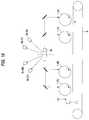
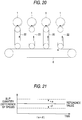
- An image forming apparatus using the intermediate transfer belt is such that, as shown in Fig. 19, a plurality of photoconductive drums 1 are arranged in a line and an intermediate transfer belt 22 is so installed along the photoconductive drums 1 that it is brought into contact with all of the photoconductive drums 1 and further a conveyer channel of copying paper P is kept in contact with the intermediate transfer belt 22; or otherwise a plurality of photoconductive drums 1 are arranged in a line and a transfer belt 6 is so installed along the photoconductive drums 1 that it is separated from the photoconductive drums 1 and further an intermediate transfer belt 22 is disposed between each photoconductive drum 1 and the transfer belt 6 as shown in Fig. 20.
- the toner-image-carrier driving means may be what is capable of driving all the toner image carriers to rotate in a predetermined period and besides controlling the rotational period of each toner image carrier; for example, it is one-to-one connected each toner image carrier, has a plurality of stepping motors for rotating in conformity with the period of an input signal and a plurality of voltage control type oscillating circuits for supplying a signal of a predetermined period to each stepping motor; or otherwise it is one-to-one connected each toner image carrier, has a plurality of stepping motors for rotating in conformity with the period of an input signal, an oscillating circuit for oscillating a signal of a predetermined frequency and a frequency divider circuit for dividing the frequency of the signal according to the set-up condition.
- the rotational speed of each stepping motor is made adjustable by controlling the control voltage supplied to the each voltage control type oscillating circuit in conformity with the position-shift correction quantity, whereas in the case of the latter, the rotational speed of each stepping motor is made adjustable by varying the dividing ratio of the frequency divider circuit in conformity with the position-shift correction quantity, whereby the rotational period of the toner image carrier can be adjusted.
- An ideal rotational period of the toner image carrier determined at the time it is designed such as a reference rotational period may be set in the substantially middle of a period regulating range by means of the toner-image-carrier driving means.
- the rotational period of each toner image carrier is allowed to have a necessary period difference while variation in the rotational period of each toner image carrier is suppressed,
- the reference rotational period is set at the middle value in the period adjustment range
- the variation in the rotational period under control according to the present invention can be halved in comparison with a case where the period adjustment range is set from one direction of the reference rotational period.
- the actual slip quantity of the toner image carrier can be suppressed as close to a target slip quantity as possible (see Fig. 21).
- the control by the toner-image-carrier driving means may be exerted at the time no image is formed since it is feared that because of a transient phenomenon due to the control thus exerted thereby, lack of uniformity is possible in the rotational speed of the toner image carrier.
- the voltage control type oscillating circuit is used for the toner-image-carrier driving means, such control may be exerted at the time no image is formed because ringing as the transient phenomenon produced in the control voltage may appear as the distortion of the image.
- the position-shift correction quantity detecting means may be any one of which is capable of detecting the position-shift correction quantity of each monochromatic toner image in the multicolor toner image or the value correlated thereto and outputting the position-shift correction quantity corresponding to the detected result; for example, what is capable of optically reading the multicolor toner image so as to detect the position shift quantity of each monochromatic toner image in the read image and outputting the detected result as the position-shift correction quantity or otherwise optically reading a transfer material with a color-shift detecting pattern formed thereon so as to detect the position shift quantity of each pattern in the read image and outputting the detected result as the position-shift correction quantity.
- the position-shift correction quantity detecting means may be what is used for detecting actual position shift quantity with respect to a position where the toner image on a monochromatic toner image basis (i.e., detecting absolute position shift quantity) or detecting the mutual position shift quantity of the monochromatic toner images in the multicolor toner image (i.e., detecting relative position shift quantity).
- the image forming apparatus may be provided with the position-shift correction quantity detecting means for detecting the position-shift correction quantity of each monochromatic toner image in the multicolor toner image or the value correlated thereto and outputting the position-shift correction quantity corresponding to the detected result, and toner-image-carrier driving means for controlling the period of rotational driving of each toner image carrier in conformity with the position-shift correction quantity; in other words, it is possible to adjust a period extending from the formation of a monochromatic toner image on each toner image carrier up to the formation of each monochromatic toner image on the transfer material, that is, the monochromatic toner images can be superposed on the transfer material without shifting.
- a color shift can be corrected without adjusting any other control signal and the like since the color shift is corrected by adjusting the rotational period of each toner image carrier.
- the color shift in the multicolor toner image can also be corrected to substantially zero with fine resolution only by adjusting the rotational period of each toner image carrier, whereby the position-shift correction quantity is adjustable through the correction technique according to the present invention even in a case where the position-shift correction quantity is slightly greater than one exposure width.
- exposure means for subjecting each latent image carrier to exposure scanning on a one pixel basis and forming a latent image on each latent image carrier on a one pixel width basis by superposing image information on the exposure light when the monochromatic toner image is formed on each latent image carrier may be provided; the exposure means may control timing at which the image information is superposed on the exposure light in conformity with the position-shift correction quantity; and with respect to adjustment of one pixel width or less, toner-image-carrier driving means may control the period of rotational driving of each toner image carrier.
- the exposure means may have, for example, a rotatable polygon mirror which is provided one-to-one for the latent image carrier, and a light emitting element capable of emitting light according to image information and provided one-to-one for the latent image carrier, so that the polygon mirror and the light emitting element in pair form a latent image on each latent image carrier or otherwise it may have a rotatable polygon mirror and a light emitting element capable of emitting light according to image information and provided one-to-one for the latent image carrier, so that each light emitting element emits exposure light to the polygon mirror to make the light reflected therefrom form a latent image on each latent image carrier.
- the fluctuating range of the period under the control of rotational driving period of the toner image carrier can be suppressed in a very small fluctuating range corresponding to one pixel width to the utmost.
- secondary trouble such as an increase in the fluctuation of slip quantity at the transfer position due to the control of the period and an increase in the fluctuation of development efficiency and transfer efficiency due to the control of the period.
- exposure means for subjecting each latent image carrier to exposure scanning on the basis of a plurality of pixels and forming a latent image on each latent image carrier on the basis of a plurality of pixel widths by superposing image information on the exposure light when the monochromatic toner image is formed on each latent image carrier may be provided; the exposure means may control timing at which the image information is superposed on the exposure light in conformity with the position-shift correction quantity; and with respect to adjustment of the plurality of pixel widths or less, the toner-image-carrier driving means may control the period of rotational driving of each toner image carrier.
- the exposure means may have, for example, a rotatable polygon mirror which is provided one-to-one for the latent image carrier, and a light emitting element capable of emitting light according to image information and provided one-to-plurality for the latent image carrier, so that the polygon mirror and a set of light emitting elements in pair form a latent image on each latent image carrier or otherwise it may have a rotatable polygon mirror and a light emitting element capable of emitting light according to image information and provided one-to-plurality for the latent image carrier, so that each set of light emitting elements emits exposure light to the polygon mirror to make the light reflected therefrom form a latent image on each latent image carrier.
- the fluctuating range of the period under the control of rotational driving period of the toner image carrier can be suppressed in a very small fluctuating range corresponding to the plurality of pixel widths to the utmost.
- secondary trouble such as an increase in the fluctuation of slip quantity at the transfer position due to the control of the period and an increase in the fluctuation of development efficiency and transfer efficiency due to the control of the period.
- the exposure means needs not switch over the allocation of image information to each light emitting element, that is, the combination of the image information and the light emitting element and makes it possible only to control the timing at which the image information is superposed on the exposure light as in the case of making exposure-scanning on one pixel basis, thus preventing the arrangement from becoming particularly complicated.
- the technique of subjecting the latent image carrier to exposure scanning on the basis of the plurality of pixels is generally utilized for the image forming apparatus designed to attain high resolution and even when a dual beam is used for exposure scanning, for example, the one exposure width is not made extremely wider than that in the case of exposure scanning with a single beam and this means the fluctuating range of the period under the control of the rotational driving period of the toner image carrier is kept as small as that with the use of such a single beam.
- a color shift of one exposure width or less has not been corrected only by a system of operating an exposure device or a system of moving the optical axis of such an exposure device, that is, an expensive system having a complicated mechanism.
- the correcting technique according to the present invention allows a color shift to be corrected simply and less costly.
- the exposure means which has the polygon mirror and the light emitting element and is used for subjecting each latent image carrier to exposure scanning on a one-to-plurality pixel basis and forming a latent image on each latent image carrier on a one exposure width basis by superposing image information on the exposure light when the monochromatic toner image is formed on each latent image carrier may be provided; the exposure means may control timing at which the image information is superposed on the exposure light in conformity with the position-shift correction quantity; and with respect to adjustment of one exposure width or less, the exposure means may control the rotational phase of each polygon mirror, whereas the toner-image-carrier driving means may control the period of rotational driving of each toner image carrier.
- the fluctuating range of the period under the control of rotational driving period of the toner image carrier can be suppressed within width controllable by the rotational phase of the polygon mirror.
- the fluctuating width of the slip is especially suppressed in the image forming apparatus above, moreover, a so-called hollow character in an image and the like, for example, can simultaneously be prevented by finely setting up slip quantity.
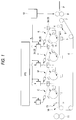
- Fig. 1 is a schematic block diagram of an image forming apparatus as Embodiment 1 of the invention.
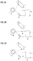
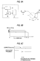
- Figs. 2A to 2C are one diagram explanatory of an image forming operation of each toner image forming unit of the image forming apparatus of Fig. 1.
- Figs. 3A to 3C are the other diagram explanatory of an image forming operation of each toner image forming unit of the image forming apparatus of Fig. 1.
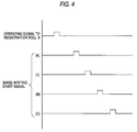
- Fig. 4 is a timing chart for explaining the timing relation of an output signal of a coarse synchronizing control unit in the image forming apparatus of Fig. 1.
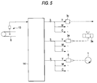
- Fig. 5 is an overall conceptual drawing of a fine synchronizing control unit in the image forming apparatus of Fig. 1.
- Fig. 6 is the first block diagram of the principal part of the fine synchronizing control unit of Fig. 5.
- Fig. 7 is the second block diagram of the principal part of the fine synchronizing control unit of Fig. 5.
- Figs. 8A to 8D are diagram explanatory of the relation between a divided signal and a polygon mirror.
- Figs. 9A to 9C are the third block diagram of the principal part of the fine synchronizing control unit of Fig. 5.
- Fig. 10 is a diagram explanatory of the operating state at a registration control cycle for color shift correction.
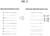
- Fig. 11 is a diagram explanatory of a registration control pattern to be formed on printing paper in a cycle of Fig. 10.
- Fig. 12 is a flowchart showing the operation of position-shift correction quantity calculating means in the cycle of Fig. 10 (total).
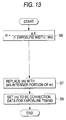
- Fig. 13 is a flowchart showing the operation of position-shift correction quantity calculating means in the cycle of Fig. 10 (detailed flowchart of S2).
- Fig. 14 is a flowchart showing the operation of position-shift correction quantity calculating means in the cycle of Fig. 10 (detailed flowchart of S3).
- Fig. 15 is a flowchart showing the operation of position-shift correction quantity calculating means in the cycle of Fig. 10 (detailed flowchart of S4).
- Fig. 16 is a schematic block diagram of an image forming apparatus as Embodiment 2 of the invention.
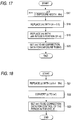
- Fig. 17 is one flowchart showing the operation of a position-shift correction quantity calculating means in the image forming apparatus of Fig. 16.
- Fig. 18 is the other flowchart showing the operation of a position-shift correction quantity calculating means in the image forming apparatus of Fig. 16.
- Fig. 19 is a schematic block diagram of an image forming apparatus as Embodiment 3 of the invention.
- Fig. 20 is another block diagram of an image forming apparatus using an intermediate transfer belt as a toner image carrier.
- Fig. 21 is an example of setting a period adjusting range with respect to a reference rotational period of a toner image carrier.
- Fig. 1 shows a full-color copying machine embodying the present invention.
- the aforementioned image forming apparatus has an image processing system (IPS) for extracting information about images of black, yellow, magenta and cyan colors from predetermined full-color image information, and an image output system for forming a multicolor toner image, namely, a predetermined full-color image by forming monochromatic toner images of respective colors and superposing the plurality of monochromatic toner images on a transfer material.
- IPS image processing system
- the image output system has four monochromatic toner image forming units K, Y, M, C for forming monochromatic toner images of predetermined colors, and a transfer material conveyer unit for conveying a transfer material P such as printing paper, OHP sheets and the like.
- the monochromatic toner image forming units K, Y, M, C are arrange in a line and the transfer material conveyer unit is installed so that the transfer material P can be conveyed along the line.
- Each of the monochromatic toner image forming units has a rotatable photoconductive drum 1; a uniform charger corotron 2 for charging the photoconductive drum with a predetermined potential, the uniform charger corotron 2 being installed opposite to the photoconductive drum 1; a laser exposure unit 3 for exposing to light the photoconductive drum 1 according to information about an image of each color so as to form an electrostatic latent image on the photoconductive drum 1; a developing device 4 for storing toner of the same color as the color designated by the image information so as to develop the electrostatic latent image involved with that toner; a transfer corotron 5 for transferring the toner image to the transfer material P; a photoconductive-drum cleaning means (not shown); and a photoconductive-drum driving stepping motor 6 for driving the photoconductive drum 1 to rotate in a predetermined cycle.
- a position of the photoconductive drum 1 exposed to light by the laser exposure unit 3 is called an exposure position
- the position between the photoconductive drum 1 and the transfer corotron 5 is hereinafter called a transfer position
- the laser exposure unit 3 has one rotatable polygon mirror 3a, one laser diode 3b for emitting light according a predetermined light emission control signal, a light emission control unit 3c for outputting a light emission control signal at predetermine timing on receiving and according to the information about the image of each color, an SOS sensor (scanning start signal) 3d for detecting the rotational phase of the polygon mirror 3a from the light reflected therefrom, and a polygon-mirror driving stepping motor 3e for turning the polygon mirror 3a in the predetermined cycle and phase.
- the laser exposure unit 3 exposes to light the photoconductive drum 1 by letting the polygon mirror 3a reflect the exposure light of the laser diode 3b.
- black toner image forming unit K is indicated with reference numerals, this is also the same with the other monochromatic toner image forming units.
- Each of the monochromatic toner image forming units K, Y, M, C causes the uniform charger corotron 2 to charge the photoconductive drum 1.
- the laser exposure unit 3 exposes to light the photoconductive drum 1 according to the information about the image of each color and the developing device 4 develops the electrostatic latent image involved, so that a monochromatic toner image of each color is formed on the photoconductive drum 1.
- an image-writing start signal is input to the light emission control unit 3c as shown in Figs. 2A to 3C and when the detection signal of the SOS sensor 3d is input thereto, the light emission control unit 3c controls the light emission of the laser diode 3b according to the image information.
- an electrostatic latent image of one pixel width is formed on the photoconductive drum 1 along its axis of rotation (see Figs. 2A to 2C and Fig. 3A). Further, the photoconductive drum 1 is turned by one scanning width until the next reflective surface (reflective surface of No.
- each of the monochromatic toner image forming units K, Y, M, C repeats this process a predetermined number of times, whereby the monochromatic toner image forming unit can form a predetermined electrostatic latent image, that is, a monochromatic toner image on the photoconductive drum 1.
- the transfer material conveyer unit has a transfer belt 6 rotatably installed so as to pass the transfer position of each of the monochromatic toner image forming units K, Y, M, C; a transfer-belt driving means 7 for driving the transfer belt 6 to rotate; a pair of registration rolls 8 for supplying a transfer material P to the transfer belt 6 at predetermined timing; a transfer-material drawing device 9 which is disposed opposite to the transfer belt 6 and used for electrostatically drawing the transfer material P to the transfer belt 6; a transfer-material peeling device 10 which is disposed opposite to the transfer belt 6 and used for peeling the transfer material P off the transfer belt 6 by eliminating charge from the transfer material P; and a pair of fixing rollers 11 for heat-pressing the transfer material P.
- the registration rolls 8 supplies the transfer material P to the transfer belt 6 at the predetermined timing and the transfer belt 6 conveys the printing paper P while drawing it and besides the fixing rolls 11 discharges the printing paper P, thus enabling the transfer material conveyer unit to convey the transfer material P.
- the operations of the four monochromatic toner image forming units K, Y, M, C have to be synchronized with the operation of the transfer material conveyer unit in order to form a desired multicolor toner image on the transfer material P by superposing the monochromatic toner images, namely, to form a predetermined full-color image on the transfer material P.
- a coarse synchronizing control unit 12 for generating the image-writing start signal to each of the monochromatic toner image forming units K, Y, M, C and an operating signal to the registration rolls 8 of the transfer material conveyer unit in predetermined timing relationship
- a fine synchronizing control unit for finely and properly regulating image-writing start timing of each of the monochromatic toner image forming units K, Y, M, C.
- the coarse synchronizing control unit 12 generates the image-writing start signal and a registration-roll operating signal in a manner that allows synchronization is attained according to the design specification based on, for example, the surface speed of the photoconductive drum 1, the surface speed of the transfer belt 6, the angle set between the exposure position and the transfer position, the distance between the registration rolls 8 and each transfer position and the like. Incidentally, the timing relation among them is like what is shown in Fig. 4, for example.
- the fine synchronizing control unit controls the image-writing start timing, the rotational phase of the polygon mirror and the period of rotation of the photoconductive drum 1 in each of the monochromatic toner image forming unit Y for the yellow toner image, the monochromatic toner image forming unit M for the magenta toner image and the monochromatic toner image forming unit C for the cyan toner image, so that these toner images are superposed on the black toner image at the respective transfer positions.
- the fine synchronizing control unit may needless to say be adapted for use in controlling the image-writing start timing and the rotational phases of the polygon mirrors, and the period of rotation of the photoconductive drums 1 in all of the monochromatic toner image forming units K, Y, M, C so as to superpose the monochromatic toner images.
- the fine synchronizing control unit has, for example, as shown in Fig. 5, an image reading sensor 13 for reading an image on the transfer belt 6, and a position-shift correction quantity calculating means 14 for detecting the position shift quantity of each toner image with respect to the black toner image and outputting a position-shift correction quantity based on the detected result.
- the fine synchronizing control unit controls light emission control start timing of the light emission control unit 3c in each of the monochromatic toner image forming units Y, M, C; the rotational phase of the polygon mirror 3a in each of the monochromatic toner image forming units Y, M, C; and the period of rotation of the photoconductive drum 1 in each of the monochromatic toner image forming units Y, M, C.
- the fine synchronizing control unit may control the light emission control start timing of the light emission control unit 3c by varying the delay time value set by the delay time setting means 15 according the position-shift correction quantity.
- the fine synchronizing control unit may control the rotational phase of the polygon mirror 3a by means of, for example, an oscillator for outputting a predetermined cyclic clock signal, a frequency divider 17 for converting the clock signal into clock signals different in phase, and three selectors 18 for outputting one of the four divided clock signals in conformity with setting-up as shown in Fig. 7. More specifically, the outputs of the three selectors 18 are input to the polygon mirrors driving motors 3e of the each of the monochromatic toner image forming units Y, M, C and the selection of the three selectors 18 is varied in accordance with the position-shift correction quantity.
- Fig. 8 shows the relation between the divided clock signal and the rotational phase thereby in examples of polygon mirrors 3a in the form of a hexagonal four division.
- the fine synchronizing control unit may control the rotational phase of the photoconductive drum 1 by means of, for example, a reference voltage generator 19 for outputting a reference voltage in accordance with the positing-shift correction quantity, a voltage control type oscillating circuit for outputting the predetermined cyclic signal in response to the reference voltage, and a drive control circuit 21 for driving the photoconductive-drum driving stepping motor 6 according to the predetermined cyclic signal as shown in Fig. 9A.
- a reference voltage generator 19 for outputting a reference voltage in accordance with the positing-shift correction quantity
- a voltage control type oscillating circuit for outputting the predetermined cyclic signal in response to the reference voltage
- a drive control circuit 21 for driving the photoconductive-drum driving stepping motor 6 according to the predetermined cyclic signal as shown in Fig. 9A.
- the period of the output signal of the voltage control type oscillating circuit 20 becomes disturbed when the reference voltage is varied and if an image is written and transferred at this timing, the image may become distorted and distorted. Therefore, it has been arranged to vary such a reference voltage at the time the image is not formed (at least at non-transfer or non-image writing time).
- a registration control cycle for color shift correction is effected at the non-image writing time and the fine synchronizing control unit makes fine adjustment in that cycle.
- a registration control pattern is formed in each of the monochromatic toner image forming units Y, M, C and the registration control pattern of each color is transferred onto the transfer belt 6, so that the image on the transfer belt 6 is read (sampled) by the image reading sensor 13.
- Fig. 10 shows a state in which the image reading sensor 13 is performing the reading operation.
- Fig. 11 shows a registration pattern (ideal registration pattern) free from a color shift and an example of variation in a measured registration pattern when the color shift occurs.
- ⁇ X refers to the registration correction quantity of each color.
- the position-shift correction quantity calculating means 14 in the cycle above calculates the registration correcting quantity of each color on the basis of the read image above (S1), successively extracts correction data for exposure timing of each color, for polygon mirror phase control and for control of the period of the photoconductive drum on the basis of the registration correcting quantity (S2 - S4), and terminates the operation by setting these data (S5).
- a method of calculating correction data for exposure timing of each color on the basis of the registration correcting quantity in the cycle above is to, for example, calculate an integer portion as the correction data when the registration correcting quantity above is divided by one exposure width (the width of one pixel according to this embodiment of the invention) (S6 - S8) as shown in Fig. 13.
- a method of calculating the correction data for polygon mirror phase control in the cycle above is to, for example, calculate an integer portion as the correction data by subtracting from the registration correcting quantity the quantity of correction resulting from the exposure timing correction and dividing the value obtained through the substraction by one phase control width (the width shift of the toner image produced when the phase of the polygon mirror 3a is shifted by one) (S9, S10, S12, S13) as shown in Fig. 14.
- a method of calculating the correction data for control of the period of the photoconductive drum in the cycle above is to, for example, calculate the correction data by subtracting from the registration correcting quantity the quantity of the exposure timing correction and the polygon mirror phase correction and converting the value obtained into angular velocity (S14 - S16).
- Step S11 of Fig. 14 further, 0.5 is added to what is obtained by dividing the value obtained through the substraction by the one phase control width when the correction data for the polygon mirror phase control, whereby control of the period of the photoconductive drum 1 is effected by correcting the reference rotational period of the photoconductive drum 1 to its forward or backward status.
- 0.5 is added to what is obtained by dividing the value obtained through the substraction by the one phase control width when the correction data for the polygon mirror phase control, whereby control of the period of the photoconductive drum 1 is effected by correcting the reference rotational period of the photoconductive drum 1 to its forward or backward status.
- the full-color image was set free from a color shift and a hollow character and besides had excellent image quality.
- an image forming apparatus employs four laser diodes 3b for irradiating one polygon mirror 3a with exposure light and causes the polygon mirror 3a to reflect the exposure light to a corresponding photoconductive drum 1.
- a fine synchronizing control unit has an image reading sensor 13 for reading an image on a transfer belt 6 and a position-shift correction quantity calculating means 14 for detecting the transfer position shift of the read image of each color toner with respect to the read image of black toner on the basis of the images read by the image reading sensor 13 and outputting position-shift correction quantity on the basis of the detected results.
- the light emission control start timing of a light emission control unit 3c in each of the monochromatic toner image forming units Y, M, C and the rotational period of the photoconductive drum 1 are controlled according to the position-shift correction quantity.
- the hardware configuration other than what has been described above is similar to that of Embodiment 1 of the invention.
- a predetermined full-color image was formed on copying paper P with the image forming apparatus likewise after the registration control cycle for the color shift correction was executed.
- the full-color image was set free from a color shift and a hollow character and besides had excellent image quality.
- An image forming apparatus has, as shown in Fig. 19, a plurality of photoconductive drums 1 arranged in a line, an intermediate transfer belt 22 so installed along the photoconductive drums 1 that it is brought into contact with all of the photoconductive drums 1, and a conveyer channel of copying paper P in contact with the intermediate transfer belt 22.
- a monochromatic toner image formed on each photoconductive drum 1 is superposed one another (i.e., a multicolor toner image is directly formed on the intermediate transfer belt) and the images superposed thereon are collectively transferred onto the printing paper P passed through the conveyer channel, so that an image is formed on the printing paper.
- the image reading sensor 13 in Embodiment 1 is installed opposite to the intermediate transfer belt 22, and the light emission control start timing of a light emission control unit 3c in each of the monochromatic toner image forming units Y, M, C, the rotational phase of a polygon mirror 3a in each of the monochromatic toner image forming units Y, M, C and the rotational period of the photoconductive drum 1 in each of the monochromatic toner image forming units Y, M, C are controlled on the basis of the images read by the image reading sensor 13 (an arrangement of members in this case is similar to what is applicable to Embodiment 1).
- a predetermined full-color image was formed on copying paper P with the image forming apparatus likewise after the registration control cycle for the color shift correction was executed.
- the full-color image was set free from a color shift and a hollow character and besides had excellent image quality.
- a color shift can be corrected by adjusting the rotational period of each toner image carrier without adjusting any other control signal or the like in the image forming apparatus according to the present invention, hence it is possible to adjust even a color shift of one exposure width or less with high resolution and consequently to seek for high image quality.
Landscapes
- Engineering & Computer Science (AREA)
- Multimedia (AREA)
- Signal Processing (AREA)
- Physics & Mathematics (AREA)
- General Physics & Mathematics (AREA)
- Color Electrophotography (AREA)
Applications Claiming Priority (3)
| Application Number | Priority Date | Filing Date | Title |
|---|---|---|---|
| JP175172/96 | 1996-07-04 | ||
| JP08175172A JP3104741B2 (ja) | 1996-07-04 | 1996-07-04 | 画像形成装置 |
| JP17517296 | 1996-07-04 |
Publications (3)
| Publication Number | Publication Date |
|---|---|
| EP0816930A2 true EP0816930A2 (fr) | 1998-01-07 |
| EP0816930A3 EP0816930A3 (fr) | 1999-02-10 |
| EP0816930B1 EP0816930B1 (fr) | 2005-10-26 |
Family
ID=15991534
Family Applications (1)
| Application Number | Title | Priority Date | Filing Date |
|---|---|---|---|
| EP97111080A Expired - Lifetime EP0816930B1 (fr) | 1996-07-04 | 1997-07-02 | Appareil de formation d'images |
Country Status (4)
| Country | Link |
|---|---|
| US (1) | US6163327A (fr) |
| EP (1) | EP0816930B1 (fr) |
| JP (1) | JP3104741B2 (fr) |
| DE (1) | DE69734421T2 (fr) |
Cited By (8)
| Publication number | Priority date | Publication date | Assignee | Title |
|---|---|---|---|---|
| EP0860748A1 (fr) * | 1997-02-17 | 1998-08-26 | Océ-Technologies B.V. | Méthode de la correction automatique de la registration d'une image et système de tranfert d'une image utilisant ce méthode |
| EP0994618A1 (fr) * | 1998-10-16 | 2000-04-19 | Sagem Sa | Dispositif d'impression laser polychrome réglable |
| EP1089131A1 (fr) * | 1999-09-17 | 2001-04-04 | Fujitsu Limited | Correction de décalage des couleurs pour l'appareil de formation d'images |
| EP0818917A3 (fr) * | 1996-07-08 | 2002-08-28 | Fuji Xerox Co., Ltd. | Appareil de formation d'images |
| GB2355356B (en) * | 1999-08-19 | 2003-11-12 | Hewlett Packard Co | Four beam electrophotographic printing apparatus |
| EP1628167A2 (fr) | 2004-07-01 | 2006-02-22 | Ricoh Co., Ltd. | Dispositif pour former et réproduire d'images et le procédé de transfert d'images |
| EP1575258A3 (fr) * | 2004-03-09 | 2007-12-05 | Ricoh Company, Ltd. | Appareil de formation d'image, méthode pour le contrôler, ordinateur, et cartouche de traitement |
| EP1898269A1 (fr) * | 2006-09-06 | 2008-03-12 | RICOH Co., Ltd. | Dispositif de formation d'image et procédé de correction de déviation |
Families Citing this family (17)
| Publication number | Priority date | Publication date | Assignee | Title |
|---|---|---|---|---|
| US6309064B1 (en) * | 1997-11-20 | 2001-10-30 | Canon Kabushiki Kaisha | Printing apparatus |
| US6774923B2 (en) | 2002-05-31 | 2004-08-10 | Lexmark International, Inc. | Dual polygon laser printhead for a color printer |
| JP4599199B2 (ja) * | 2005-03-18 | 2010-12-15 | 株式会社リコー | 画像形成装置 |
| DE602005018863D1 (de) | 2004-08-18 | 2010-03-04 | Ricoh Kk | Bilderzeugungsvorrichtung mit einer Antriebsgeschwindigkeitsregelung der photoempfindlichen Elemente |
| JP4728649B2 (ja) * | 2005-01-07 | 2011-07-20 | 株式会社リコー | 画像形成装置、プリンタ装置、ファクシミリ装置及び複写機 |
| CN100552556C (zh) * | 2005-03-08 | 2009-10-21 | 夏普株式会社 | 成像装置 |
| US7233761B2 (en) * | 2005-07-13 | 2007-06-19 | Ricoh Company, Ltd. | Method and apparatus for transferring multiple toner images and image forming apparatus |
| JP4820733B2 (ja) * | 2005-12-09 | 2011-11-24 | 株式会社リコー | 画像形成装置 |
| JP4773227B2 (ja) * | 2006-02-21 | 2011-09-14 | 株式会社リコー | 画像形成装置、感光体回転補正方法、およびその方法をコンピュータに実行させるプログラム |
| US7693468B2 (en) | 2006-04-28 | 2010-04-06 | Ricoh Company, Ltd. | Image forming apparatus capable of effectively forming a quality color image |
| JP5006086B2 (ja) * | 2006-04-28 | 2012-08-22 | 株式会社リコー | 画像形成装置 |
| US8026940B2 (en) * | 2006-10-30 | 2011-09-27 | Kyocera Mita Corporation | Image forming apparatus |
| JP4815334B2 (ja) | 2006-12-07 | 2011-11-16 | 株式会社リコー | 画像形成装置 |
| JP4915453B2 (ja) * | 2010-01-28 | 2012-04-11 | ブラザー工業株式会社 | 画像形成システムおよび画像形成装置 |
| US9052513B2 (en) * | 2011-05-06 | 2015-06-09 | Lexmark International, Inc. | Laser scan unit for an imaging device |
| JP6123940B1 (ja) * | 2016-09-28 | 2017-05-10 | 富士ゼロックス株式会社 | 画像形成装置 |
| JP6744804B2 (ja) * | 2016-11-15 | 2020-08-19 | キヤノン株式会社 | 撮像装置 |
Family Cites Families (13)
| Publication number | Priority date | Publication date | Assignee | Title |
|---|---|---|---|---|
| GB2127744B (en) * | 1982-08-17 | 1986-07-02 | Canon Kk | Multicolour printing |
| JPS636577A (ja) * | 1986-06-27 | 1988-01-12 | Ricoh Co Ltd | カラ−作像装置 |
| EP0478005B1 (fr) * | 1987-04-28 | 1995-06-28 | Canon Kabushiki Kaisha | Appareil de formation d'images multiples |
| JPH04131875A (ja) * | 1990-09-25 | 1992-05-06 | Canon Inc | 画像形成装置 |
| JP3130034B2 (ja) * | 1990-11-28 | 2001-01-31 | 株式会社東芝 | 画像形成装置 |
| JP3272756B2 (ja) * | 1992-01-14 | 2002-04-08 | キヤノン株式会社 | 画像形成装置 |
| US5442388A (en) * | 1992-01-16 | 1995-08-15 | Xerox Corporation | Method and means for correcting lateral registration errors |
| US5541637A (en) * | 1992-07-30 | 1996-07-30 | Brother Kogyo Kabushiki Kaisha | Image exposure apparatus with compensation for variations in scanning rate |
| JPH06246975A (ja) * | 1993-02-25 | 1994-09-06 | Mitsubishi Heavy Ind Ltd | カラー画像作成装置 |
| JP3067495B2 (ja) * | 1993-12-03 | 2000-07-17 | 富士ゼロックス株式会社 | 画像形成装置 |
| JPH07271266A (ja) * | 1994-03-31 | 1995-10-20 | Canon Inc | 画像記録装置および画像記録方法 |
| JPH08278680A (ja) * | 1995-04-05 | 1996-10-22 | Toshiba Corp | 画像形成装置ならびに画像形成装置の制御方法 |
| JPH09146329A (ja) * | 1995-11-20 | 1997-06-06 | Fuji Xerox Co Ltd | 画像形成装置 |
-
1996
- 1996-07-04 JP JP08175172A patent/JP3104741B2/ja not_active Expired - Lifetime
-
1997
- 1997-06-30 US US08/886,043 patent/US6163327A/en not_active Expired - Lifetime
- 1997-07-02 EP EP97111080A patent/EP0816930B1/fr not_active Expired - Lifetime
- 1997-07-02 DE DE69734421T patent/DE69734421T2/de not_active Expired - Lifetime
Cited By (14)
| Publication number | Priority date | Publication date | Assignee | Title |
|---|---|---|---|---|
| EP0818917A3 (fr) * | 1996-07-08 | 2002-08-28 | Fuji Xerox Co., Ltd. | Appareil de formation d'images |
| EP0860748A1 (fr) * | 1997-02-17 | 1998-08-26 | Océ-Technologies B.V. | Méthode de la correction automatique de la registration d'une image et système de tranfert d'une image utilisant ce méthode |
| EP0994618A1 (fr) * | 1998-10-16 | 2000-04-19 | Sagem Sa | Dispositif d'impression laser polychrome réglable |
| FR2784617A1 (fr) * | 1998-10-16 | 2000-04-21 | Sagem | Dispositif d'impression laser polychrome reglable |
| GB2355356B (en) * | 1999-08-19 | 2003-11-12 | Hewlett Packard Co | Four beam electrophotographic printing apparatus |
| EP1089131A1 (fr) * | 1999-09-17 | 2001-04-04 | Fujitsu Limited | Correction de décalage des couleurs pour l'appareil de formation d'images |
| US6393244B1 (en) | 1999-09-17 | 2002-05-21 | Fujitsu Limited | Color shift correcting structure of image forming apparatus |
| EP1575258A3 (fr) * | 2004-03-09 | 2007-12-05 | Ricoh Company, Ltd. | Appareil de formation d'image, méthode pour le contrôler, ordinateur, et cartouche de traitement |
| US7313352B2 (en) | 2004-03-09 | 2007-12-25 | Ricoh Company, Ltd. | Image forming apparatus, method of controlling same, machine-readable medium and process cartridge |
| EP1628167A2 (fr) | 2004-07-01 | 2006-02-22 | Ricoh Co., Ltd. | Dispositif pour former et réproduire d'images et le procédé de transfert d'images |
| EP1628167A3 (fr) * | 2004-07-01 | 2006-03-01 | Ricoh Co., Ltd. | Dispositif pour former et réproduire d'images et le procédé de transfert d'images |
| US7280789B2 (en) | 2004-07-01 | 2007-10-09 | Ricoh Company, Ltd. | Image forming and reproducing apparatus, and image transferring method for controlling rotation speeds of image carriers |
| EP1898269A1 (fr) * | 2006-09-06 | 2008-03-12 | RICOH Co., Ltd. | Dispositif de formation d'image et procédé de correction de déviation |
| US7848687B2 (en) | 2006-09-06 | 2010-12-07 | Ricoh Company, Ltd. | Image forming device and deviation correcting method |
Also Published As
| Publication number | Publication date |
|---|---|
| DE69734421D1 (de) | 2005-12-01 |
| US6163327A (en) | 2000-12-19 |
| EP0816930B1 (fr) | 2005-10-26 |
| JPH1020607A (ja) | 1998-01-23 |
| EP0816930A3 (fr) | 1999-02-10 |
| JP3104741B2 (ja) | 2000-10-30 |
| DE69734421T2 (de) | 2006-05-24 |
Similar Documents
| Publication | Publication Date | Title |
|---|---|---|
| US6163327A (en) | Image forming apparatus for controlling the period of rotational driving of each toner image carrier | |
| US6839078B2 (en) | Image forming apparatus which changes clock frequencies in accordance with recording sheet shrinkage | |
| US6219516B1 (en) | Systems and methods for reducing image registration errors | |
| US5600404A (en) | Correction of misregistration in an image forming apparatus depending on multiple regions of a transfer belt | |
| US6154628A (en) | Image forming device with misregistration correction achieved by photo-conductor speed controlled variation of latent image tilt | |
| JP3236178B2 (ja) | マルチビームレーザ記録装置 | |
| US5319433A (en) | Electrophotographing apparatus for forming color image | |
| US7538918B2 (en) | Toner image forming apparatus including gradation control | |
| JP2950721B2 (ja) | 光走査制御装置 | |
| JP4131313B2 (ja) | 画像出力装置の制御装置及びこれを用いた画像形成装置 | |
| CA2113020C (fr) | Imprimante couleur electrophotographique et methode d'impression faisant appel a ladite imprimante | |
| US7130097B2 (en) | Image forming apparatus | |
| JP3307077B2 (ja) | タンデムタイプのカラー画像形成装置 | |
| JPH1020616A (ja) | 画像形成装置 | |
| JP3587484B2 (ja) | 光ビーム走査装置 | |
| JP2005010440A (ja) | 電子写真装置 | |
| JPH06130871A (ja) | カラー画像形成装置 | |
| JP7828550B2 (ja) | 画像形成装置 | |
| JPH11218696A (ja) | 多色画像形成装置 | |
| JP2007286460A (ja) | 画像補正方法及び画像形成装置 | |
| JP3596970B2 (ja) | 光ビーム走査装置 | |
| JP2000238328A (ja) | レジストレーションコントロール方法、及び多色画像形成装置 | |
| JPH11237567A (ja) | 多色画像形成装置及び方法 | |
| JP2023091826A (ja) | 画像形成装置の調節方法、画像形成装置 | |
| JPH1024622A (ja) | 多色電子写真装置 |
Legal Events
| Date | Code | Title | Description |
|---|---|---|---|
| PUAI | Public reference made under article 153(3) epc to a published international application that has entered the european phase |
Free format text: ORIGINAL CODE: 0009012 |
|
| AK | Designated contracting states |
Kind code of ref document: A2 Designated state(s): DE FR GB |
|
| PUAL | Search report despatched |
Free format text: ORIGINAL CODE: 0009013 |
|
| AK | Designated contracting states |
Kind code of ref document: A3 Designated state(s): AT BE CH DE DK ES FI FR GB GR IE IT LI LU MC NL PT SE |
|
| 17P | Request for examination filed |
Effective date: 19990414 |
|
| AKX | Designation fees paid |
Free format text: DE FR GB |
|
| 17Q | First examination report despatched |
Effective date: 20011005 |
|
| GRAP | Despatch of communication of intention to grant a patent |
Free format text: ORIGINAL CODE: EPIDOSNIGR1 |
|
| GRAS | Grant fee paid |
Free format text: ORIGINAL CODE: EPIDOSNIGR3 |
|
| GRAA | (expected) grant |
Free format text: ORIGINAL CODE: 0009210 |
|
| AK | Designated contracting states |
Kind code of ref document: B1 Designated state(s): DE FR GB |
|
| REG | Reference to a national code |
Ref country code: GB Ref legal event code: FG4D |
|
| REF | Corresponds to: |
Ref document number: 69734421 Country of ref document: DE Date of ref document: 20051201 Kind code of ref document: P |
|
| ET | Fr: translation filed | ||
| PLBE | No opposition filed within time limit |
Free format text: ORIGINAL CODE: 0009261 |
|
| STAA | Information on the status of an ep patent application or granted ep patent |
Free format text: STATUS: NO OPPOSITION FILED WITHIN TIME LIMIT |
|
| 26N | No opposition filed |
Effective date: 20060727 |
|
| PGFP | Annual fee paid to national office [announced via postgrant information from national office to epo] |
Ref country code: GB Payment date: 20130626 Year of fee payment: 17 |
|
| PGFP | Annual fee paid to national office [announced via postgrant information from national office to epo] |
Ref country code: DE Payment date: 20130626 Year of fee payment: 17 |
|
| PGFP | Annual fee paid to national office [announced via postgrant information from national office to epo] |
Ref country code: FR Payment date: 20130724 Year of fee payment: 17 |
|
| REG | Reference to a national code |
Ref country code: DE Ref legal event code: R119 Ref document number: 69734421 Country of ref document: DE |
|
| GBPC | Gb: european patent ceased through non-payment of renewal fee |
Effective date: 20140702 |
|
| REG | Reference to a national code |
Ref country code: FR Ref legal event code: ST Effective date: 20150331 |
|
| PG25 | Lapsed in a contracting state [announced via postgrant information from national office to epo] |
Ref country code: DE Free format text: LAPSE BECAUSE OF NON-PAYMENT OF DUE FEES Effective date: 20150203 |
|
| REG | Reference to a national code |
Ref country code: DE Ref legal event code: R119 Ref document number: 69734421 Country of ref document: DE Effective date: 20150203 |
|
| PG25 | Lapsed in a contracting state [announced via postgrant information from national office to epo] |
Ref country code: FR Free format text: LAPSE BECAUSE OF NON-PAYMENT OF DUE FEES Effective date: 20140731 Ref country code: GB Free format text: LAPSE BECAUSE OF NON-PAYMENT OF DUE FEES Effective date: 20140702 |