EP0817206A1 - Verfahren und Vorrichtung zur geometrischen Kontrolle eines Leitrohrs - Google Patents
Verfahren und Vorrichtung zur geometrischen Kontrolle eines Leitrohrs Download PDFInfo
- Publication number
- EP0817206A1 EP0817206A1 EP97401453A EP97401453A EP0817206A1 EP 0817206 A1 EP0817206 A1 EP 0817206A1 EP 97401453 A EP97401453 A EP 97401453A EP 97401453 A EP97401453 A EP 97401453A EP 0817206 A1 EP0817206 A1 EP 0817206A1
- Authority
- EP
- European Patent Office
- Prior art keywords
- rod
- guide
- guide tube
- sheath
- bosses
- Prior art date
- Legal status (The legal status is an assumption and is not a legal conclusion. Google has not performed a legal analysis and makes no representation as to the accuracy of the status listed.)
- Ceased
Links
- 238000000034 method Methods 0.000 title claims description 7
- 238000006073 displacement reaction Methods 0.000 claims abstract description 12
- 239000000523 sample Substances 0.000 claims abstract description 12
- 238000005259 measurement Methods 0.000 claims abstract description 11
- 239000004020 conductor Substances 0.000 claims description 7
- 230000007246 mechanism Effects 0.000 claims description 4
- 239000003758 nuclear fuel Substances 0.000 claims description 4
- 230000004323 axial length Effects 0.000 claims description 2
- 239000000446 fuel Substances 0.000 description 3
- 238000009434 installation Methods 0.000 description 2
- 238000004519 manufacturing process Methods 0.000 description 2
- 239000003507 refrigerant Substances 0.000 description 2
- 230000009172 bursting Effects 0.000 description 1
- 230000015556 catabolic process Effects 0.000 description 1
- 235000009508 confectionery Nutrition 0.000 description 1
- 239000002826 coolant Substances 0.000 description 1
- 238000001514 detection method Methods 0.000 description 1
- 238000010586 diagram Methods 0.000 description 1
- 239000002184 metal Substances 0.000 description 1
- 238000005096 rolling process Methods 0.000 description 1
- 229910001220 stainless steel Inorganic materials 0.000 description 1
- 239000010935 stainless steel Substances 0.000 description 1
- 238000003860 storage Methods 0.000 description 1
- 230000009182 swimming Effects 0.000 description 1
- 229920002994 synthetic fiber Polymers 0.000 description 1
- XLYOFNOQVPJJNP-UHFFFAOYSA-N water Substances O XLYOFNOQVPJJNP-UHFFFAOYSA-N 0.000 description 1
Images

Classifications
-
- G—PHYSICS
- G21—NUCLEAR PHYSICS; NUCLEAR ENGINEERING
- G21C—NUCLEAR REACTORS
- G21C17/00—Monitoring; Testing ; Maintaining
- G21C17/06—Devices or arrangements for monitoring or testing fuel or fuel elements outside the reactor core, e.g. for burn-up, for contamination
-
- G—PHYSICS
- G01—MEASURING; TESTING
- G01B—MEASURING LENGTH, THICKNESS OR SIMILAR LINEAR DIMENSIONS; MEASURING ANGLES; MEASURING AREAS; MEASURING IRREGULARITIES OF SURFACES OR CONTOURS
- G01B7/00—Measuring arrangements characterised by the use of electric or magnetic techniques
- G01B7/34—Measuring arrangements characterised by the use of electric or magnetic techniques for measuring roughness or irregularity of surfaces
- G01B7/345—Measuring arrangements characterised by the use of electric or magnetic techniques for measuring roughness or irregularity of surfaces for measuring evenness
-
- Y—GENERAL TAGGING OF NEW TECHNOLOGICAL DEVELOPMENTS; GENERAL TAGGING OF CROSS-SECTIONAL TECHNOLOGIES SPANNING OVER SEVERAL SECTIONS OF THE IPC; TECHNICAL SUBJECTS COVERED BY FORMER USPC CROSS-REFERENCE ART COLLECTIONS [XRACs] AND DIGESTS
- Y02—TECHNOLOGIES OR APPLICATIONS FOR MITIGATION OR ADAPTATION AGAINST CLIMATE CHANGE
- Y02E—REDUCTION OF GREENHOUSE GAS [GHG] EMISSIONS, RELATED TO ENERGY GENERATION, TRANSMISSION OR DISTRIBUTION
- Y02E30/00—Energy generation of nuclear origin
- Y02E30/30—Nuclear fission reactors
Definitions
- the object of the present invention is to control the straightness of a nuclear fuel assembly guide tube, this guide tube comprising an area of reduced diameter in its terminal part.
- the fuel assembly guide tubes have often an area of diameter reduced to their lower part. This reduced diameter is very little greater than that of a pencil of control cluster likely to descend into the tube.
- the purpose of the reduced diameter zone is to slow the fall of the cluster by hydraulic rolling of the refrigerant contained in the tube.
- the fuel assembly After passing through the reactor, the fuel assembly can present deformations giving to the guide tube a non-rectilinear shape. It is important to detect the existence and the importance of such deformations, before reloading in the reactor to guarantee the free passage of adjustment cluster rods in the guide tubes.
- the invention aims to provide a device and a method allowing to obtain a plot of the interior deformations a guide tube, usable while the assembly is kept under water, preferably by using, for cause the required relative displacements, the means which are required for handling the fuel assembly.
- the invention notably proposes a device comprising a cane of which a distal part has successively, from the end of the cane, a guide bulge having a diameter allowing it to cross the reduced diameter area with gentle friction and two bosses with at least the closest to the bulge carries at least two sets of diametrically stressed sensors opposite, provided with connecting conductors with the end cane proximal and comprising a sheath capable to slide in the current part of the guide tube and on the rod and come into abutment against the choked area, the displacement of the sheath towards the distal part being limited by an abutment support on the rod in a determined position where the sheath surrounds the cane.
- the stress sensors can consist of resistive strain gauges fixed on the rod and providing an output signal which is an increasing function stresses and deformations undergone by the cane.
- this rod will be made up of two parts, one of which carries the sensors.
- the assembly consisting of the paired cane and the scabbard constitutes a set which, when using the device, is connected to a measurement unit by the connecting conductors.
- the device will generally supplemented by means for determining orientation relative rod and guide tube.
- the device can, from the deformations measured in two mutually orthogonal directions, transverse to the axis of the explored tube, provide a trace of the amplitude and orientation of the deformations at all reduced diameter area levels.
- the device can also be used to measure possible deformations of the tube outside the area of reduced diameter; for this, we provide the bosses with rings whose external diameter is such that they slide with friction soft in the running part of the guide tube.
- the invention also provides a method using works a set of the genre defined above, according to which said assembly is inserted into the guide tube by displacement relative of the guide tube and the assembly until it stops scabbard against the strangled area, relative displacements of the guide tube and the rod so to sweep through the bosses the entire area of reduced diameter, and the amplitude and orientation are deduced distortions of the signals supplied by the sensors and a measurement of the displacement of the rod along the axis of the guide tube.
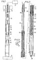
- the device whose essential elements are shown in figure 1 is intended to measure the deformations of a tube guide 10 connecting the upper end piece 12 and the lower end piece 14 of a nuclear fuel assembly.
- This guide tube present, near its lower end and in some case up to this end, a zone 16 of reduced diameter whose possible deformations can have consequences serious, including the trapping of a pencil control clusters.
- the device allows to measure the deformations of the guide tube at this level, so give for example the route of the axis of the guide tube in the reduced diameter area.
- the device can be viewed as comprising a measuring rod 18 and a sleeve 20 movable relative to one another to each other in the axial direction (i.e. vertically when the assembly is in its normal orientation).
- the cane 18 is itself in several assembled parts, of so as to facilitate its manufacture and to adjust its flexibility at each level.
- it comprises a tubular probe body 22, a flexible sheath or articulated 23 and a wiring box 24.
- the upper end threaded of the tubular probe body is screwed on the part threaded end of the flexible sheath. This sheath is itself blocked on the wiring box and a ring 26 can be provided around the connection to avoid bursting.
- the probe body 22 is in the form of a rod between a guide terminal bulge 25 of diameter such that it can cross the diameter area with gentle friction reduced and a first boss 28 which can circulate in friction sweet in this area. 27 slots in the bulge guide terminal allow the passage of the refrigerant along the tube, during pool measurements.
- the probe body is hollow to form a four ducts central passage duct, four in number for example, containing connection conductors of measurement sensors with the outside. Spacious grooves in the bosses, similar to the slots 27, allow the coolant passage.
- the spacings 1 1 and 1 2 between the terminal guide bulge 25, the first boss 28 and the second boss 30, are much smaller than the axial length of the zone of reduced diameter, to allow the deformation of the zone of measurement to be measured. reduced diameter along the latter.
- the probe body 22 has a flexibility allowing it to flex to adapt to deformations in the constricted area, which cause stresses measured by the sensors.
- a set of sensors is placed near the first boss. he has at least four regularly distributed sensors around the axis, so that their output signals allow to calculate the amplitude and the orientation of the deformations possible.
- the sensors associated with the first boss 28 can be attached to the rod immediately below this boss and connected to the conductors by oblique holes drilled in the first boss. Other sensors may be associated with the second boss to also perform a measured. However, the second boss will generally not be used only to guide the probe body.
- the housing 24 can be formed by a rod, for example cruciform to delimit passages intended for sheaths 32.
- the bulged upper end of the housing receives the end an electrical cable 36 for connection with a measure 37 placed at a distance.
- the lower end, also bulged, the housing 24 is fixed to the sheath 23.
- this sheath may for example be of synthetic material, while the other parts of the measuring rod are made of metal, stainless steel by example.
- the sheath 20 has a length slightly greater than 1 1 +1 2 . Its outside diameter is constant and allows it to slide with gentle friction in the current part of the guide tube. However, this outside diameter is high enough for the sheath to abut against the start of the zone of reduced diameter of the guide tube, when the assembly constituted by the rod and the sheath descends into the guide tube.
- the internal diameter of the sheath 20 is such that it can slide over the terminal bulge and bosses, except at its upper part which has a supporting shoulder 38 on the boss 30. This internal diameter also ensures the continuity with the reduced diameter area.
- the measuring rod 18 and the sheath 20 are provided for be connectable to respective operating tubes 40 and 42, a fraction of which is shown in dashed lines on the figure 2. These tubes are connected to operating mechanisms allowing them to go up and down.
- the housing 24 is connected to the probe body 22 by at least one emergency cable 44 whose ends can be welded in oblique holes made respectively in a ferrule bottom of the housing 24 and in the second boss 30.
- Figure 4 shows a lift 45 mounted against the wall of a storage pool, comprising a fixed cage, formed by two pairs of vertical rails 46 fixed to the wall by arms 48 and surmounted by a platform 50. On this platform can be fixed a mechanism 52 of operation of the tubes 40 and 42.
- a nacelle 54 for receiving of an assembly, placed between the rails of the cage, is consisting of side members connected by frames, a bottom 58 and an inlet chute 60. The bottom and the chute are fitted with vertical guide rollers for the nacelle. The bottom 58 is hooked to an operating cable 61 wound on the winch drum 62.
- the sequence of operations can then be as follows.
- a assembly to be checked is placed in the nacelle and this one came down with a winch.
- Rod and sheath set is lowered into the guide tube to be checked, identifying its orientation, (for example by matching a coordinate system carried by the rod or the operating tube) until all the bosses have exceeded the reduced diameter zone. From the moment when the end of the sheath 20 comes into press on the reduced diameter area, the sheath moves compared to the rod, which provides a reference original for measurement.
- Winch 62 is set step to raise the assembly at constant speed.
- the assembly placed in the nacelle goes up at constant speed then that the rod remains fixed and that the sheath also rises.
- the two pairs of sensors provide signals representative of the deformation of the rod in two directions mutually orthogonal.
- the remote measuring device 37 includes means of memorization and means of calculating the deformation along the two orthogonal directions. These means of computation also perform a vector summation following the two orthogonal directions. Simultaneously, the displacement of the assembly is raised. We thus obtain the curve representative of the deformation over the entire length of the reduced diameter portion 16.
- the mechanism 52 for operating the tubes can be provided a force sensor which detects the coming of the rod in stop against the lower cap of the guide tube. This detection can cause automatic rewinding of the rod or reversing the movement of the elevator. A second measurement can be performed during this sense movement reverse.
- the device also makes it possible to control the part current of the guide tube by adding calibrated rings on the bulge 25 and the bosses 28 and 30. These rings have a diameter such that they can slide with gentle friction in the current part.
- a number of pairs of sensors greater than two can be expected.
- three sets of sensors can be placed at 60 ° one of the other.
Landscapes
- Physics & Mathematics (AREA)
- Engineering & Computer Science (AREA)
- General Physics & Mathematics (AREA)
- Plasma & Fusion (AREA)
- General Engineering & Computer Science (AREA)
- High Energy & Nuclear Physics (AREA)
- Monitoring And Testing Of Nuclear Reactors (AREA)
Applications Claiming Priority (2)
| Application Number | Priority Date | Filing Date | Title |
|---|---|---|---|
| FR9607927A FR2750491B1 (fr) | 1996-06-26 | 1996-06-26 | Procede et dispositif de controle geometrique d'un tube guide |
| FR9607927 | 1996-06-26 |
Publications (1)
| Publication Number | Publication Date |
|---|---|
| EP0817206A1 true EP0817206A1 (de) | 1998-01-07 |
Family
ID=9493424
Family Applications (1)
| Application Number | Title | Priority Date | Filing Date |
|---|---|---|---|
| EP97401453A Ceased EP0817206A1 (de) | 1996-06-26 | 1997-06-23 | Verfahren und Vorrichtung zur geometrischen Kontrolle eines Leitrohrs |
Country Status (3)
| Country | Link |
|---|---|
| US (1) | US5852642A (de) |
| EP (1) | EP0817206A1 (de) |
| FR (1) | FR2750491B1 (de) |
Families Citing this family (7)
| Publication number | Priority date | Publication date | Assignee | Title |
|---|---|---|---|---|
| US7707735B2 (en) * | 2007-06-14 | 2010-05-04 | The Boeing Company | Hole angularity gage and methods of operation and manufacture therefor |
| US8631563B2 (en) | 2009-04-14 | 2014-01-21 | Ge-Hitachi Nuclear Energy Americas Llc | Apparatus and method for removing a dry tube assembly from a nuclear reactor pressure vessel |
| DE102009047760A1 (de) * | 2009-11-12 | 2011-06-09 | Areva Np Gmbh | Verfahren und Vorrichtung zum Ermitteln der Verformung eines Brennelementes eines Druckwasserreaktors |
| CN102708935B (zh) * | 2012-03-23 | 2015-10-14 | 中广核工程有限公司 | 核电站模拟控制棒组件 |
| US10304577B2 (en) * | 2015-08-12 | 2019-05-28 | Westinghouse Electric Company Llc | Method for measuring bow/twist of a fuel assembly |
| US11692805B2 (en) * | 2021-08-25 | 2023-07-04 | Saudi Arabian Oil Company | Identification system for tubulars |
| CN113932702B (zh) * | 2021-09-22 | 2022-07-15 | 成都飞机工业(集团)有限责任公司 | 一种检测装置的底座及其加工方法 |
Citations (6)
| Publication number | Priority date | Publication date | Assignee | Title |
|---|---|---|---|---|
| US4318776A (en) * | 1978-07-21 | 1982-03-09 | Kraftwerk Union Aktiengesellschaft | Measuring lance for boiling-water nuclear reactors |
| EP0059301A2 (de) * | 1981-02-27 | 1982-09-08 | NTG Neue Technologien GmbH & Co. KG | Brennelementenkastenmessmaschine |
| FR2587107A1 (fr) * | 1985-09-12 | 1987-03-13 | Westinghouse Electric Corp | Appareil de controle de rectitude de tubes |
| US4655990A (en) * | 1980-03-26 | 1987-04-07 | Commissariat A L'energie Atomique | Fuel assemblies for nuclear reactors |
| FR2601180A1 (fr) * | 1986-04-24 | 1988-01-08 | Westinghouse Electric Corp | Appareil pour systeme integre d'inspection d'assemblage combustible pour reacteurs nucleaires. |
| US5268940A (en) * | 1992-11-02 | 1993-12-07 | The Babcock & Wilcox Company | Reactor upper internals inspection device |
Family Cites Families (1)
| Publication number | Priority date | Publication date | Assignee | Title |
|---|---|---|---|---|
| FR2694836B1 (fr) * | 1992-08-11 | 1994-11-10 | Framatome Sa | Dispositif de contrôle des éléments de guidage d'un tube-guide des équipements internes supérieurs d'un réacteur nucléaire à eau sous pression. |
-
1996
- 1996-06-26 FR FR9607927A patent/FR2750491B1/fr not_active Expired - Lifetime
-
1997
- 1997-06-23 EP EP97401453A patent/EP0817206A1/de not_active Ceased
- 1997-06-26 US US08/882,729 patent/US5852642A/en not_active Expired - Fee Related
Patent Citations (6)
| Publication number | Priority date | Publication date | Assignee | Title |
|---|---|---|---|---|
| US4318776A (en) * | 1978-07-21 | 1982-03-09 | Kraftwerk Union Aktiengesellschaft | Measuring lance for boiling-water nuclear reactors |
| US4655990A (en) * | 1980-03-26 | 1987-04-07 | Commissariat A L'energie Atomique | Fuel assemblies for nuclear reactors |
| EP0059301A2 (de) * | 1981-02-27 | 1982-09-08 | NTG Neue Technologien GmbH & Co. KG | Brennelementenkastenmessmaschine |
| FR2587107A1 (fr) * | 1985-09-12 | 1987-03-13 | Westinghouse Electric Corp | Appareil de controle de rectitude de tubes |
| FR2601180A1 (fr) * | 1986-04-24 | 1988-01-08 | Westinghouse Electric Corp | Appareil pour systeme integre d'inspection d'assemblage combustible pour reacteurs nucleaires. |
| US5268940A (en) * | 1992-11-02 | 1993-12-07 | The Babcock & Wilcox Company | Reactor upper internals inspection device |
Also Published As
| Publication number | Publication date |
|---|---|
| US5852642A (en) | 1998-12-22 |
| FR2750491B1 (fr) | 1998-09-04 |
| FR2750491A1 (fr) | 1998-01-02 |
Similar Documents
| Publication | Publication Date | Title |
|---|---|---|
| EP2269022B1 (de) | System zur gewinnung von informationen über röhren und entsprechendes verfahren | |
| FR2517104A1 (fr) | Procede d'examen d'un assemblage combustible de reacteur nucleaire et machine d'examen pour la mise en oeuvre de ce procede | |
| EP0213028B1 (de) | Verfahren und Vorrichtung zur Überprüfung von Stäben eines Stabkreuzes für ein Kernbrennstabbündel | |
| FR2530346A1 (fr) | Procede et dispositif d'acquisition de signaux sismiques dans un forage | |
| EP0028191B1 (de) | Vorrichtung zum Feststellen von Planheitsfehlern in einem sich unter Spannung bewegenden Band | |
| FR2750491A1 (fr) | Procede et dispositif de controle geometrique d'un tube guide | |
| FR2526532A1 (fr) | Appareil pour le controle des tubes d'un echangeur de chaleur a une distance donnee de l'extremite de ces tubes | |
| FR2539510A1 (fr) | Dispositif de controle de tubes cintres a sonde propulsee pneumatiquement | |
| US20040075432A1 (en) | Flexible shaft with a helically wound data cable supporting a smooth outer sleeve for eddy current probe | |
| FR2743184A1 (fr) | Dispositif et procede de controle de crayons de grappe de commande pour reacteur nucleaire | |
| EP2326913A1 (de) | Einrichtung zum messen und korregieren eines parallelismusfehlers eines kernbrennstabs | |
| CA2108185C (fr) | Dispositif support d'une sonde de detection et de localisation de defauts eventuels a l'interieur d'un alesage | |
| FR2542297A1 (fr) | Dispositifs de mesure et d'indication pour treuils de tirage de cables | |
| FR2753299A1 (fr) | Dispositif miniaturise, auto-alimente et a reponse rapide, pour la detection etagee d'un flux neutronique, notamment dans un reacteur nucleaire | |
| EP0241343A1 (de) | Vorrichtung zur Fernmessung des Aussendurchmessers eines zylinderförmigen Elementes, das aus der Oberfläche einer Platte vorspringt | |
| FR2640607A1 (fr) | Dispositif de levage de charges | |
| FR2712663A1 (fr) | Appareil d'inspection de l'état physique de canalisations non accessibles ou visitables par l'homme. | |
| CN109764826B (zh) | 一种高速检测桥梁拉索外形截面形状的检测仪 | |
| FR2613116A1 (fr) | Appareil pour inspecter le profil d'une tige, notamment une tige de commande utilisee dans un reacteur nucleaire a eau pressurisee | |
| EP1166040B1 (de) | Bragg-gitter-dehnungsmesser und verfahren zur herstellung dieses dehnungsmessers | |
| CA2081012C (fr) | Dispositif de mesure du deplacement d'une tete d'injection d'un mat de forage | |
| WO1991012377A2 (fr) | Perfectionnement aux mecanismes de man×uvre de plate-formes marines, procede de gestion de ces mecanismes et installation pour la mise en ×uvre du procede | |
| FR2979741A1 (fr) | Dispositif d'examen pour l'examen de composants de reacteur nucleaire | |
| FR2613835A1 (fr) | Dispositif de deplacement et de mise en rotation d'un outil a l'interieur d'un tube et son utilisation pour le controle des tubes d'un generateur de vapeur | |
| EP4264172A1 (de) | Vorrichtung zur messung des mechanischen spiels in einem hydraulischen system |
Legal Events
| Date | Code | Title | Description |
|---|---|---|---|
| PUAI | Public reference made under article 153(3) epc to a published international application that has entered the european phase |
Free format text: ORIGINAL CODE: 0009012 |
|
| AK | Designated contracting states |
Kind code of ref document: A1 Designated state(s): BE DE ES GB SE |
|
| 17P | Request for examination filed |
Effective date: 19980612 |
|
| AKX | Designation fees paid |
Free format text: BE DE ES GB SE |
|
| RBV | Designated contracting states (corrected) |
Designated state(s): BE DE ES GB SE |
|
| GRAG | Despatch of communication of intention to grant |
Free format text: ORIGINAL CODE: EPIDOS AGRA |
|
| 17Q | First examination report despatched |
Effective date: 20000823 |
|
| STAA | Information on the status of an ep patent application or granted ep patent |
Free format text: STATUS: THE APPLICATION HAS BEEN REFUSED |
|
| 18R | Application refused |
Effective date: 20010103 |