EP0817323B1 - Modularbuchse mit Anzeigenleuchte - Google Patents
Modularbuchse mit Anzeigenleuchte Download PDFInfo
- Publication number
- EP0817323B1 EP0817323B1 EP97107447A EP97107447A EP0817323B1 EP 0817323 B1 EP0817323 B1 EP 0817323B1 EP 97107447 A EP97107447 A EP 97107447A EP 97107447 A EP97107447 A EP 97107447A EP 0817323 B1 EP0817323 B1 EP 0817323B1
- Authority
- EP
- European Patent Office
- Prior art keywords
- housing
- modular connector
- light emitting
- connector
- terminals
- Prior art date
- Legal status (The legal status is an assumption and is not a legal conclusion. Google has not performed a legal analysis and makes no representation as to the accuracy of the status listed.)
- Expired - Lifetime
Links
- 230000000295 complement effect Effects 0.000 claims description 12
- 239000004020 conductor Substances 0.000 claims description 10
- 230000000694 effects Effects 0.000 claims description 8
- 230000000717 retained effect Effects 0.000 claims description 6
- 238000003780 insertion Methods 0.000 claims description 4
- 230000037431 insertion Effects 0.000 claims description 4
- RYGMFSIKBFXOCR-UHFFFAOYSA-N Copper Chemical compound [Cu] RYGMFSIKBFXOCR-UHFFFAOYSA-N 0.000 claims description 3
- 229910052802 copper Inorganic materials 0.000 claims description 3
- 239000010949 copper Substances 0.000 claims description 3
- 229920006267 polyester film Polymers 0.000 claims 1
- 229910000679 solder Inorganic materials 0.000 claims 1
- 239000002184 metal Substances 0.000 description 8
- 229910052751 metal Inorganic materials 0.000 description 8
- 230000008878 coupling Effects 0.000 description 4
- 238000010168 coupling process Methods 0.000 description 4
- 238000005859 coupling reaction Methods 0.000 description 4
- 230000003068 static effect Effects 0.000 description 4
- 230000000007 visual effect Effects 0.000 description 4
- 230000009977 dual effect Effects 0.000 description 3
- 238000012986 modification Methods 0.000 description 3
- 230000004048 modification Effects 0.000 description 3
- IUTPYMGCWINGEY-UHFFFAOYSA-N 2,3',4,4',5-Pentachlorobiphenyl Chemical compound C1=C(Cl)C(Cl)=CC=C1C1=CC(Cl)=C(Cl)C=C1Cl IUTPYMGCWINGEY-UHFFFAOYSA-N 0.000 description 2
- 230000015572 biosynthetic process Effects 0.000 description 2
- 238000005192 partition Methods 0.000 description 2
- 239000010409 thin film Substances 0.000 description 2
- 239000000853 adhesive Substances 0.000 description 1
- 230000001070 adhesive effect Effects 0.000 description 1
- 238000013461 design Methods 0.000 description 1
- 239000003989 dielectric material Substances 0.000 description 1
- 239000012777 electrically insulating material Substances 0.000 description 1
- 230000005611 electricity Effects 0.000 description 1
- 239000010408 film Substances 0.000 description 1
- 230000001795 light effect Effects 0.000 description 1
- 230000000670 limiting effect Effects 0.000 description 1
- 230000014759 maintenance of location Effects 0.000 description 1
- 239000000463 material Substances 0.000 description 1
- 230000013011 mating Effects 0.000 description 1
- 230000036961 partial effect Effects 0.000 description 1
- 230000002829 reductive effect Effects 0.000 description 1
- 238000012795 verification Methods 0.000 description 1
Images

Classifications
-
- H—ELECTRICITY
- H01—ELECTRIC ELEMENTS
- H01R—ELECTRICALLY-CONDUCTIVE CONNECTIONS; STRUCTURAL ASSOCIATIONS OF A PLURALITY OF MUTUALLY-INSULATED ELECTRICAL CONNECTING ELEMENTS; COUPLING DEVICES; CURRENT COLLECTORS
- H01R12/00—Structural associations of a plurality of mutually-insulated electrical connecting elements, specially adapted for printed circuits, e.g. printed circuit boards [PCB], flat or ribbon cables, or like generally planar structures, e.g. terminal strips, terminal blocks; Coupling devices specially adapted for printed circuits, flat or ribbon cables, or like generally planar structures; Terminals specially adapted for contact with, or insertion into, printed circuits, flat or ribbon cables, or like generally planar structures
- H01R12/70—Coupling devices
- H01R12/77—Coupling devices for flexible printed circuits, flat or ribbon cables or like structures
- H01R12/79—Coupling devices for flexible printed circuits, flat or ribbon cables or like structures connecting to rigid printed circuits or like structures
-
- H—ELECTRICITY
- H01—ELECTRIC ELEMENTS
- H01R—ELECTRICALLY-CONDUCTIVE CONNECTIONS; STRUCTURAL ASSOCIATIONS OF A PLURALITY OF MUTUALLY-INSULATED ELECTRICAL CONNECTING ELEMENTS; COUPLING DEVICES; CURRENT COLLECTORS
- H01R13/00—Details of coupling devices of the kinds covered by groups H01R12/70 or H01R24/00 - H01R33/00
- H01R13/66—Structural association with built-in electrical component
- H01R13/717—Structural association with built-in electrical component with built-in light source
-
- H—ELECTRICITY
- H01—ELECTRIC ELEMENTS
- H01R—ELECTRICALLY-CONDUCTIVE CONNECTIONS; STRUCTURAL ASSOCIATIONS OF A PLURALITY OF MUTUALLY-INSULATED ELECTRICAL CONNECTING ELEMENTS; COUPLING DEVICES; CURRENT COLLECTORS
- H01R13/00—Details of coupling devices of the kinds covered by groups H01R12/70 or H01R24/00 - H01R33/00
- H01R13/66—Structural association with built-in electrical component
- H01R13/717—Structural association with built-in electrical component with built-in light source
- H01R13/7175—Light emitting diodes (LEDs)
-
- G—PHYSICS
- G09—EDUCATION; CRYPTOGRAPHY; DISPLAY; ADVERTISING; SEALS
- G09F—DISPLAYING; ADVERTISING; SIGNS; LABELS OR NAME-PLATES; SEALS
- G09F13/00—Illuminated signs; Luminous advertising
- G09F13/20—Illuminated signs; Luminous advertising with luminescent surfaces or parts
- G09F13/22—Illuminated signs; Luminous advertising with luminescent surfaces or parts electroluminescent
-
- H—ELECTRICITY
- H01—ELECTRIC ELEMENTS
- H01R—ELECTRICALLY-CONDUCTIVE CONNECTIONS; STRUCTURAL ASSOCIATIONS OF A PLURALITY OF MUTUALLY-INSULATED ELECTRICAL CONNECTING ELEMENTS; COUPLING DEVICES; CURRENT COLLECTORS
- H01R12/00—Structural associations of a plurality of mutually-insulated electrical connecting elements, specially adapted for printed circuits, e.g. printed circuit boards [PCB], flat or ribbon cables, or like generally planar structures, e.g. terminal strips, terminal blocks; Coupling devices specially adapted for printed circuits, flat or ribbon cables, or like generally planar structures; Terminals specially adapted for contact with, or insertion into, printed circuits, flat or ribbon cables, or like generally planar structures
- H01R12/50—Fixed connections
- H01R12/51—Fixed connections for rigid printed circuits or like structures
- H01R12/55—Fixed connections for rigid printed circuits or like structures characterised by the terminals
- H01R12/58—Fixed connections for rigid printed circuits or like structures characterised by the terminals terminals for insertion into holes
-
- H—ELECTRICITY
- H01—ELECTRIC ELEMENTS
- H01R—ELECTRICALLY-CONDUCTIVE CONNECTIONS; STRUCTURAL ASSOCIATIONS OF A PLURALITY OF MUTUALLY-INSULATED ELECTRICAL CONNECTING ELEMENTS; COUPLING DEVICES; CURRENT COLLECTORS
- H01R13/00—Details of coupling devices of the kinds covered by groups H01R12/70 or H01R24/00 - H01R33/00
- H01R13/648—Protective earth or shield arrangements on coupling devices, e.g. anti-static shielding
- H01R13/6485—Electrostatic discharge protection
-
- H—ELECTRICITY
- H01—ELECTRIC ELEMENTS
- H01R—ELECTRICALLY-CONDUCTIVE CONNECTIONS; STRUCTURAL ASSOCIATIONS OF A PLURALITY OF MUTUALLY-INSULATED ELECTRICAL CONNECTING ELEMENTS; COUPLING DEVICES; CURRENT COLLECTORS
- H01R24/00—Two-part coupling devices, or either of their cooperating parts, characterised by their overall structure
- H01R24/60—Contacts spaced along planar side wall transverse to longitudinal axis of engagement
- H01R24/62—Sliding engagements with one side only, e.g. modular jack coupling devices
-
- H—ELECTRICITY
- H01—ELECTRIC ELEMENTS
- H01R—ELECTRICALLY-CONDUCTIVE CONNECTIONS; STRUCTURAL ASSOCIATIONS OF A PLURALITY OF MUTUALLY-INSULATED ELECTRICAL CONNECTING ELEMENTS; COUPLING DEVICES; CURRENT COLLECTORS
- H01R4/00—Electrically-conductive connections between two or more conductive members in direct contact, i.e. touching one another; Means for effecting or maintaining such contact; Electrically-conductive connections having two or more spaced connecting locations for conductors and using contact members penetrating insulation
- H01R4/02—Soldered or welded connections
- H01R4/023—Soldered or welded connections between cables or wires and terminals
Definitions
- the present invention relates to modular jacks and, more particularly, to modular jacks having line status indicators.
- Modular jacks are well known, especially for telephone communications equipment wherein it is necessary to provide a releasable coupling of one device to another. Modular jacks are frequently used for the interconnection of computing devices to the telephone system, as they provide a compact, cost effective, and user friendly interface.
- the modular jacks releasably connect four and in some cases six or more discrete lines or circuits from one device to another via a complementary plug.
- Single or multiple (gang) jacks are made that couple single or multiple lines to single or multiple line devices.
- a connector adapted to receive a mating plug therein has a visual indicator positioned within the front wall and thus integral with the housing to provide a visual verification of the status of the electrical connection.
- the visual indicator is formed integral with the housing, it is not possible to change the indicator light should it need replacing.
- the present invention provides a modular type connector for receiving a complementary plug to effect an electrical connection between the modular connector and the plug, the modular connector having a housing defining a front face with a cavity therein, the modular connector further having a plurality of first terminals extending into the cavity and adapted to make electrical contact with corresponding second terminals on the plug,
- said connector comprising a cover plate removably secured to the front face of the connector, the cover plate having a cutout portion conforming in shape to the cavity in the modular connector, wherein a light emitting device is removably retained on said cover plate, and is adapted to be electrically coupled to one of the first or second terminals to indicate status of that terminal.
- the present invention provides a modular connector for receiving a complementary plug to effect an electrical connection therebetween, the modular connector comprising:
- the present invention provides a modular connector for receiving a complementary plug to effect an electrical connection therebetween, the modular connector comprising:
- the present invention further provides a multiple modular jack having indicator lights detachably retained by the front shield, face plate, pr bezel of the jack.
- the front shield is detachably mounted to the front face of the housing. The placement of the indicator lights on the front shield does not alter the profile of a standard multiple modular jack, and thus no modification to the housing is necessary to carry out the present invention.
- the front shield includes bracket portions that have bores therein.
- the bores removably receive and retain the indicator lights, with the front shield held onto the housing. Retention of the indicator lights is thus accomplished solely by the front shield, independent of the housing.
- the indicator lights are light emitting diodes (LEDs). This embodiment is practical for small LEDs such as 1.8mm LEDs.
- the front shield includes bracket portions with notches formed therein. The edges of the notches are received in grooves formed in the LEDs. This embodiment is practical for larger LEDs such as 3.0mm LEDs.
- the LEDs include terminals that are electrically coupled to circuits on the printed circuit board.
- the LEDs may be coupled to terminal pins that are electrically coupled to the appropriate circuits on the circuit board via a thin, flexible conductor that extends about the housing of the jack.
- the LEDs may be directly coupled to a flex circuit without a front plate, the flex circuit wrapping around the housing of the jack and coupled to the printed circuit board.
- the flex circuit may, for example, be a copper etched circuit or a film type conductor circuit.
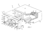
- the modular jack 10 includes a housing, generally designated 12, and a front cover, shield, or face plate, generally designated 14.
- the housing 12 is essentially hollow and defined by a top wall 16, a bottom wall 18, a right side wall 20, a left side wall 22, a rear wall 24, and a front wall 26.
- the housing is molded from an electrically insulating or dielectric material such as plastic, but any suitable material may be used.
- the modular jack 10 depicted in Fig. 1 has a middle partition, divider, or wall 28 that defines a left cavity 30 and a right cavity 32 within the housing 12.
- Integrally formed into the housing 12 at the bottom of the left cavity 30 is a channel formation 31 that serves to orient and guide the receiving plug (not shown) through a complementary plug structure (not shown).
- integrally formed into the housing 12 at the bottom of the right cavity 32 is a channel formation 33 that serves the orient and guide the receiving plug (not shown) through a complementary plug structure (not shown).
- a plurality of slots or openings 34 Disposed in the rear wall 24 at the end of the right cavity 32 is a plurality of slots or openings 34.
- One terminal or lead 36 extends through each slot 34 in a one-to-one correspondence.
- the number of slot/terminal pairs 34/36 depends on the design of the jack and the available space. Typically, four or more slot/terminal pairs 34/36 are used.
- disposed in the rear wall 24 at the end of the left cavity 30 are like slot/terminal pairs. The number of slot/terminal pairs at the end of the left cavity 30 is generally the same as for the right cavity 32.
- the face plate 14 is adapted to be removably or detachably received against the front wall 26 of the modular jack 10.
- the face plate 14 is made of a suitable electrically conducting metal.
- the face plate 14 serves as a metal shield for electrical grounding for devices attached thereto or mounted thereon.
- the face plate 14 is defined by a front face 38, a top flange 40, a bottom flange 46, a right flange 42, and a left flange 44.
- Each flange 40, 42, 44, 46 extends a short distance from and transverse relative to the front face 38 such that when the face plate 14 is positioned against the housing 12, the flanges are adjacent respective walls 16, 20, 22, 18 and hold the face plate 14 to the housing 12 by an interference or friction fit.
- the front face 38 includes a left cutout portion 50 and a right cutout portion 52 that correspond in location and dimension to the left and right openings 30, 32, respectively, to allow the plug (not shown) to fit therethrough and into the respective left and right cavities 30, 32.
- the front face 38 also includes a left bracket 54, a right bracket 56, and a middle bracket 58 each of which are disposed at the bottom of the front face 38.
- the brackets 54, 56, 58 correspond in location to cutout areas in the housing 12.
- the bracket 54 has a bore 60 with an insert or grommet 61 therein. Disposed in the bore and removably retained by the insert 61 is a light emitting device such as a light emitting diode (LED) 62.
- LED light emitting diode
- the LED 62 shown is a 1.8mm LED having two leads or terminals 64, 66 that are electrically coupled to a particular line circuit for status indication of that particular line.
- the middle bracket 58 includes two like bores (not numbered) and inserts (not numbered) that removably retain two 1.8mm LEDs 68, 70.
- the right bracket 56 includes a bore (not numbered) and insert (not numbered) that removably retains a 1.8mm LED 72.
- each LED 68, 70, 72 also includes two terminals (not numbered) associated therewith for electrical connection to a particular line circuit.
- the housing 12 is a standard dual receptacle modular jack housing and thus needs no modification to accommodate the present detachable face plate 14 with its removable LEDs 62, 68, 70, 72.
- the 1.8mm LEDs are shielded against static discharge by the face plate 14.
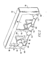
- the face plate 80 is again, preferably made of an electrically conducting metal to provide a metal shield or path for static discharges, and is designed to be detachably attached to the housing 12 without modification to the housing.
- the face plate 80 is defined by a front face 82, a top flange 84, a bottom flange 86, a left flange 88, and a right flange 90.
- the flanges 82, 84, 86, 88, 90 extend a short distance from and transverse relative to the front face 82 such that when the face plate 14 is positioned against the housing 12, the flanges are adjacent respective walls 16, 20, 22, 18 and hold the face plate 80 to the housing 12 by an interference or friction fit.
- the face plate 80 additionally includes a center partition 92 that defines left and right cutout portions 94 and 96 respectively.
- the left and right cutout portions 94 and 96 correspond in location and dimension to the left and right cavities 30, 32, respectively, to allow the plug (not shown) to fit therethrough and into the respective left and right cavities 30, 32.
- the front face 82 also has a left bracket 98, a right bracket 100, and a middle or center bracket 102 each of which are disposed at the bottom of the front face 82.
- the brackets 98, 100, 102 correspond in location to cutout areas in the housing 12.
- the left bracket 98 has a configured notch 104 therein in which is removably seated a light emitting device such as a light emitting diode (LED) 106 via grooves in the lens of the LED 106 that hold the edges of the configured notch 104. Additionally, the LED 106 has two leads 108, 110 for electrically coupling the LED 106 to a particular line circuit for status or trouble indication of that particular line.
- the right bracket 100 likewise includes a configured notch (not numbered) in which is disposed an LED 112, while the middle bracket 102 includes two configured notches (not numbered) in which are disposed LEDs 114 and 116. Although not numbered, or particularly seen in Fig. 2, each LED includes two leads for electrically coupling the particular LED to the particular line or circuit.
- the LEDs 106, 112, 114, and 116 are 3.0mm LEDs.
- the 3.0mm LEDs provide an increased indicator size relative to the 1.8mm LEDs that is somewhat more noticeable when illuminated.
- the increased size of the LED is at the expense of a face plate having less metal per the total are thereof.
- any color of LED may be used as well as size of LED as long as the supporting brackets can accommodate the particular size.
- the larger the size of LED the less metal in the face plate and thus the less shielding the face plate provides against static discharge.
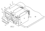
- FIG. 3 and 4 there is shown a further alternative embodiment of a face plate and LED configuration.
- the housing 12 is shown mounted upon a printed circuit board (PCB) 118.
- the face plate 120 in like manner to the previous embodiments depicted in Figs. 1 and 2, includes a front face 122, a bottom flange 124, a top flange 126, a right flange 128, and a left flange (not visible) that each extend a short distance from and transverse to the front face 122 that together provides an interference fit with the sides or walls of the housing 12 in order to detachably secure the face plate 120 to the housing 12.
- the present face plate 120 has two light emitting devices such as light emitting diodes (LEDs) per each housing cavity or receptacle that are mounted to the upper portion of the front face 122, in contrast to the face plates 14 and 80 of Figs. 1 and 2, respectively.
- LEDs light emitting diodes
- two LEDs 130 and 132 are depicted for the right receptacle of the housing 12, with a lens 142 in an exploded position.
- the LEDs 130, 132 are electrically coupled to an end 147 of a thin, flexible conductor strip 146, such as a ribbon cable, a thin film coated conductor, a copper etched circuit, or the like and may be coupled to the housing by adhesive.
- the end 147 and the upper portion of the front face 122 also includes two bores 134, 136 that receive two legs 138, 140 of the elongated lens 142.
- the lens 142 helps retain the conductor strip 146 on the housing 12 and soften the LED light effect.
- the left receptacle side includes two LEDs (not shown) electrically coupled to a thin, flexible conductor strip 148, and covered by a lens 144.
- the conductor strips 146, 148 are contiguous with the top wall 16 of the housing 12 and are electrically coupled to a plurality of terminal pins 150 that are in turn electrically coupled to the appropriate circuits on the PCB 118.
- One type of terminal pin 150 may be a Clincher Solder Tab obtainable through Berg Electronics of Etters, Pennsylvania, as part number 76216.
- the terminal pins 150 are used to electrically couple or act as a bridge between the various circuits of the conductor strips 146, 148 and the appropriate PCB 118 circuits.
- the strip 146 is retained by a U-portion 154 of the terminal pin 150.
- a flex circuit it is not necessary to have a face plate.
- the LEDs may be mounted directly to the flex circuit.
- the flex circuit may comprise as many electrical circuits as necessary to accommodate the number of LEDs.
Landscapes
- Physics & Mathematics (AREA)
- Engineering & Computer Science (AREA)
- Microelectronics & Electronic Packaging (AREA)
- Optics & Photonics (AREA)
- Details Of Connecting Devices For Male And Female Coupling (AREA)
- Illuminated Signs And Luminous Advertising (AREA)
Claims (18)
- Ein Verbinder (10) modularen Typs zum Aufnehmen eines komplementären Steckers, um eine elektrische Verbindung zwischen einem Modularverbinder (10) und einem Stecker zu bewirken, wobei der Modularverbinder (10) ein Gehäuse (12) umfasst, das eine Vorderseite (32; 82) mit einem Hohlraum (30, 32) darin definiert, wobei der Modularverbinder (10) weiter eine Vielzahl von ersten Anschlüssen (36) umfasst, die sich in den Hohlraum (30, 32) erstrecken und angepasst sind, um einen elektrischen Kontakt mit entsprechenden zweiten Anschlüssen an dem Stecker herzustellen, wobei der Verbinder (10) eine Abdeckplatte (14; 80) umfasst, die lösbar an der Vorderseite (38, 82) des Verbinders (10) befestigt ist, wobei die Abdeckplatte (14; 80) einen ausgeschnittenen Abschnitt (50, 52; 94, 96) aufweist, der in Form mit dem Hohlraum ( 30, 32) in dem Modularverbinder (10) übereinstimmt, dadurch gekennzeichnet, dass
ein lichtemittierendes Gerät (62, 68, 70, 72; 106; 112, 114, 116; 130, 134) lösbar an der Abdeckplatte ( 14; 80) gehalten ist und angepasst ist, um elektrisch mit einem der ersten oder zweiten Anschlüsse (36) verbunden zu sein, um den Status jenes Anschlusses anzuzeigen. - Der Modularverbinder (10) aus Anspruch 1, wobei das lichtemittierende Gerät (130, 134) elektrisch über einen flexiblen Stromkreis (146, 148) mit einem der ersten oder zweiten Anschlüsse verbunden ist.
- Der Modularverbinder (10) aus Anspruch 2, wobei die flexiblen Stromkreise (146, 148) einen Polyesterfilm mit einer leitfähigen Tinte umfassen.
- Der Modularverbinder (10) aus Anspruch 2, wobei die flexiblen Stromkreise (146, 148) mit einer Lötfahne (150) verbunden sind.
- Der Modularverbinder (10) aus Anspruch 2, wobei die flexiblen Stromkreise (146, 148) an einer äußeren Oberfläche (16) des Gehäuses (12) angeordnet sind.
- Der Modularverbinder (10) aus Anspruch 1, wobei die Abdeckplatte (14; 80) eine flache Frontplatte mit den ausgeschnittenen Abschnitten (50, 52; 94, 96) darin umfasst, wobei die flache Frontplatte in der Größe mit der Vorderseite (38; 82) des Gehäuses (12) übereinstimmt und ein oberes Querelement umfasst, das sich von einem oberen Ende der Frontplatte erstreckt und angepasst ist, um an einer äußeren Oberfläche einer oberen Wand (16) des Gehäuses (12) anzustoßen und um einen Abschnitt davon abzudecken, ein unteres Querelement, das sich von einem unteren Ende der Frontplatte erstreckt und angepasst ist, um an einer äußeren Oberfläche einer unteren Wand (18) des Gehäuses (12) anzustoßen und einen Abschnitt davon abzudecken, ein linkes Querelement, das sich von einem linken Ende der Frontplatte erstreckt und angepasst ist, um an einer äußeren Oberfläche einer linken Seitenwand (22) des Gehäuses (12) anzustoßen und einen Abschnitt davon abzudecken, und ein rechtes Querelement, das sich von einem rechten Ende der Frontplatte erstreckt und angepasst ist, um an einer äußeren Oberfläche einer rechten Seitenwand (20) des Gehäuses (12) anzustoßen und einen Abschnitt davon abzudecken.
- Der Verbinder (10) von Anspruch 1, weiter aufweisend eine Linse (142, 144), die lösbar von dieser Abdeckplatte (120) aufgenommen wird und über dem lichtemittierenden Gerät (130, 134) angeordnet ist.
- Ein Modularverbinder (10) zum Aufnehmen eines komplementären Steckers, um eine elektrische Verbindung zwischen zu bewirken, der Modularverbinder (10) umfassend:ein Gehäuse (12), das durch eine untere Wand (18), eine obere Wand (16), eine Rückwand (24), eine vordere Wand (26), eine linke Wand (22) undeine rechte Wand (20) definiert ist;ein Hohlraum (30, 32) in dem Gehäuse (12), der eine Öffnung in der vorderen Wand (26) aufweist;eine Vielzahl von ersten elektrischen Anschlüssen (36), die in dem Hohlraum (30, 32) angeordnet und angepasst sind, um einen elektrischen Kontakt mit zweiten elektrischen Anschlüssen an dem Stecker beim Einsetzen des Steckers in den Hohlraum herzustellen;eine Abdeckplatte (14; 80; 120) in der Größe eingestellt und konfiguriert, um an der vorderen Wand (26) aufgenommen zu werden, wobei die Abdeckplatte (14; 80; 120) einen ausgeschnittenen Abschnitt (50, 52; 94, 96) der gleichen Konfiguration wie die Öffnung hat und einen oberen Querflansch (40; 84), einen unteren Querflansch (46; 86), einen linken Querflansch (44; 88) und einen rechten Querflansch (42; 90) umfasst, wobei jeder Flansch angepasst ist, um jeweils einen Abschnitt der oberen (16), unteren (18), linken (22) und rechten (20) Wand des Gehäuses (12) zu kontaktieren, dadurch gekennzeichnet, dassder Verbinder (10) ein lichtemittierendes Gerät (86, 70, 72; 106, 112, 114, 116; 130, 134) umfasst, das lösbar durch die Abdeckplatte (14; 80; 120) gehalten wird, wobei das lichtemittierende Gerät (68, 70, 72; 106, 112, 114, 116; 130, 134) elektrisch mit einem der Vielzahl der ersten oder zweiten Anschlüsse (36) verbunden ist, um den Status der entsprechenden Leitung zu einem der Vielzahl der ersten oder zweiten Anschlüsse anzuzeigen.
- Der Modularverbinder (10) aus Anspruch 8, wobei die Abdeckplatte (14; 80) einen darin geformten Befestigungssitz umfasst, der das lichtemittierende Gerät hält.
- Der Modularverbinder (10) aus Anspruch 8, des weiteren aufweisend, eine Vielzahl von lichtemittierenden Geräten (106) einer Anzahl die gleich oder kleiner als eine Anzahl der Anschlüsse (36) ist, wobei jedes lichtemittierende Gerät (106) elektrisch mit einem unterschiedlichen Anschluss (36) verbunden ist, um den Status der Leitung des jeweils entsprechenden Anschlusses (36) anzuzeigen, und eine Vielzahl von Befestigungssitzen, die in der Abdeckplatte ausgebildet sind, die jeweils die Vielzahl von lichtemittierenden Geräten (106) halten.
- Der Modularverbinder (10) aus Anspruch 8, wobei das lichtemittierende Gerät (130, 134) elektrisch mit einem der Vielzahl der Anschlüsse über einen flexiblen Stromkreis (146, 148) verbunden ist.
- Der Modularverbinder (10) aus Anspruch 11, wobei der flexible Stromkreis (146, 148) einen kupfergeätzten Stromkreis umfasst.
- Der Modularverbinder (10) aus Anspruch 11, wobei der flexible Stromkreis (146, 148) einen siebgedruckten Leiter umfasst.
- Ein modularer Verbinder (10) zur Aufnahme eines komplementären Steckers, um eine elektrische Verbindung zwischen ihnen zu bewirken, wobei der Modularverinder (10) umfasst:ein Gehäuse (12), das eine Vorderseite (38; 82) definiert und einen Hohlraum (30, 32) darin mit einer Öffnung in der vorderen Wand (38; 82) aufweist.eine Vielzahl von ersten elektrischen Anschlüssen (36), die innerhalb des Hohlraums (30, 32) angeordnet und angepasst sind, um elektrisch mit komplementären zweiten Anschlüssen des Steckers über ein Einsetzen des Steckers in den Hohlraum (30, 32) verbunden zu werden, dadurch gekennzeichnet, dassein flexibler Stromkreis elektrisch mit mindestens einem der Vielzahl der ersten elektrischen Anschlüsse (36) verbunden ist undein lichtemittierendes Gerät (130, 132) elektrisch verbunden ist mit und direkt befestigt ist auf dem flexiblen Stromkreis, wodurch der flexible Stromkreis benachbart zu einer vorderen Wand und zu einer oberen Wand (16) des Gehäuses (12) ist, wobei das lichtemittierende Gerät (130, 132) von dem Verbinder lösbar ist.
- Der Modularverbinder (10) von Anspruch 14, weiter aufweisend eine Vielzahl von lichtemittierenden Geräten (130, 132) einer Anzahl, die gleich oder kleiner als die Vielzahl der ersten elektrischen Anschlüsse (36) ist, wobei jedes lichtemittierende Gerät (130, 132) elektrisch verbunden ist mit und direkt befestigt ist auf einem der Vielzahl der flexiblen Stromkreise.
- Der Modularverbinder (10) aus Anspruch 14, wobei eine Linse (142, 144) über dem lichtemittierenden Gerät (130, 132) angeordnet ist.
- Der Modularverbinder (10) aus Anspruch 16, wobei der flexible Stromkreis zumindest teilweise an dem Gehäuse (12) durch die Linse (142, 144) befestigt ist.
- Der Modularverbinder (10) aus Anspruch 14, wobei das Gehäuse (12) eine hintere Seite aufweist, die der Frontseite gegenüberliegt, und wobei sich der flexible Stromkreis rückwärts über die Rückseite erstreckt.
Applications Claiming Priority (2)
| Application Number | Priority Date | Filing Date | Title |
|---|---|---|---|
| US657792 | 1996-05-31 | ||
| US08/657,792 US5797767A (en) | 1996-05-31 | 1996-05-31 | Indicator light modular jack |
Publications (2)
| Publication Number | Publication Date |
|---|---|
| EP0817323A1 EP0817323A1 (de) | 1998-01-07 |
| EP0817323B1 true EP0817323B1 (de) | 2001-08-29 |
Family
ID=24638682
Family Applications (1)
| Application Number | Title | Priority Date | Filing Date |
|---|---|---|---|
| EP97107447A Expired - Lifetime EP0817323B1 (de) | 1996-05-31 | 1997-05-06 | Modularbuchse mit Anzeigenleuchte |
Country Status (7)
| Country | Link |
|---|---|
| US (1) | US5797767A (de) |
| EP (1) | EP0817323B1 (de) |
| JP (1) | JPH10134897A (de) |
| DE (1) | DE69706377T2 (de) |
| DK (1) | DK0817323T3 (de) |
| SG (1) | SG55305A1 (de) |
| TW (1) | TW356968U (de) |
Families Citing this family (46)
| Publication number | Priority date | Publication date | Assignee | Title |
|---|---|---|---|---|
| US5924890A (en) * | 1996-08-30 | 1999-07-20 | The Whitaker Corporation | Electrical connector having a virtual indicator |
| TW315990U (en) * | 1996-11-29 | 1997-09-11 | Hon Hai Prec Ind Co Ltd | Module connector |
| EP0963007B1 (de) * | 1998-06-02 | 2002-01-23 | Molex Incorporated | Elektrische Zusatzbaugruppe mit Licht-Übertragungsmitteln |
| US6174194B1 (en) * | 1998-11-09 | 2001-01-16 | Molex Incorporated | Add-on electrical assembly with light transmission means |
| EP0969551A1 (de) * | 1998-06-02 | 2000-01-05 | Molex Incorporated | Elektrischer Zusatzzusamenbau mit Licht-Übertragungsmittel |
| IL142552A0 (en) * | 1998-10-14 | 2002-03-10 | Stewart Connector Systems Inc | Modular electrical connector assemblies with magnetic filter and/or visual indicator |
| US6095856A (en) * | 1998-10-30 | 2000-08-01 | General Electric Company | Holder connector apparatus and methods |
| US6152762A (en) * | 1998-11-12 | 2000-11-28 | Berg Technology, Inc. | Modular jack with side mounted light emitting diode |
| US6256445B1 (en) * | 1998-12-11 | 2001-07-03 | Lucent Technologies Inc. | Illuminated optical connection port for use in a fiber distribution shelf assembly of a fiber administration system having integral line tracing capabilities |
| US6428361B1 (en) | 1999-05-24 | 2002-08-06 | Stewart Connector Systems, Inc. | Surface mountable connector assembly including a printed circuit board |
| US6422901B1 (en) | 1999-12-06 | 2002-07-23 | Fci Americas Technology, Inc. | Surface mount device and use thereof |
| US6179650B1 (en) * | 2000-01-12 | 2001-01-30 | Tekcon Electronics Corp. | Modularized electric connector |
| US7009525B1 (en) * | 2000-06-09 | 2006-03-07 | Rockwell Automation Technologies, Inc. | Multi-angle viewable indicator apparatus |
| US6431906B1 (en) | 2001-02-28 | 2002-08-13 | Fci Americas Technology, Inc. | Modular connectors with detachable line status indicators |
| US6457993B1 (en) * | 2001-08-31 | 2002-10-01 | Hon Hai Precision Ind. Co., Ltd. | Modular jack with LED |
| EP1315240A1 (de) * | 2001-11-24 | 2003-05-28 | Murr-Elektronik Gesellschaft mit beschränkter Haftung | Kabelklemme mit optischer Anzeige |
| US6488529B1 (en) * | 2002-01-22 | 2002-12-03 | Taimag Corporation | Socket connector assembly used in a LAN |
| US7519000B2 (en) | 2002-01-30 | 2009-04-14 | Panduit Corp. | Systems and methods for managing a network |
| US7376734B2 (en) | 2002-02-14 | 2008-05-20 | Panduit Corp. | VOIP telephone location system |
| US6663417B1 (en) * | 2002-09-20 | 2003-12-16 | Weison Technologies Co., Ltd. | Electrical connector with light emitting device |
| US6790097B1 (en) | 2003-01-08 | 2004-09-14 | Cisco Technology, Inc. | System and method for preventing cable discharge events |
| US20050141431A1 (en) | 2003-08-06 | 2005-06-30 | Caveney Jack E. | Network managed device installation and provisioning technique |
| US7207846B2 (en) | 2003-11-24 | 2007-04-24 | Panduit Corp. | Patch panel with a motherboard for connecting communication jacks |
| US6979210B2 (en) * | 2003-12-10 | 2005-12-27 | Ennova Direct, Inc. | Thumb drive with retractable USB connector |
| US7455527B2 (en) | 2004-05-03 | 2008-11-25 | Panduit Corp. | Powered patch panel |
| US7494244B1 (en) | 2005-12-21 | 2009-02-24 | J & J Electronics, Inc. | Serially controllable LED lighting systems |
| US7782202B2 (en) | 2006-10-31 | 2010-08-24 | Corning Cable Systems, Llc | Radio frequency identification of component connections |
| US7772975B2 (en) | 2006-10-31 | 2010-08-10 | Corning Cable Systems, Llc | System for mapping connections using RFID function |
| US8264355B2 (en) * | 2006-12-14 | 2012-09-11 | Corning Cable Systems Llc | RFID systems and methods for optical fiber network deployment and maintenance |
| US7760094B1 (en) | 2006-12-14 | 2010-07-20 | Corning Cable Systems Llc | RFID systems and methods for optical fiber network deployment and maintenance |
| US7965186B2 (en) | 2007-03-09 | 2011-06-21 | Corning Cable Systems, Llc | Passive RFID elements having visual indicators |
| JP4987630B2 (ja) * | 2007-08-28 | 2012-07-25 | 株式会社東芝 | 電子機器 |
| US8248208B2 (en) | 2008-07-15 | 2012-08-21 | Corning Cable Systems, Llc. | RFID-based active labeling system for telecommunication systems |
| US8731405B2 (en) * | 2008-08-28 | 2014-05-20 | Corning Cable Systems Llc | RFID-based systems and methods for collecting telecommunications network information |
| JP5353128B2 (ja) * | 2008-08-29 | 2013-11-27 | ヤマハ株式会社 | 表示装置 |
| USD622216S1 (en) | 2008-12-12 | 2010-08-24 | Woodhead Industries, Inc. | Electrical connector with illumination |
| DE102009022849B4 (de) | 2009-05-27 | 2018-03-01 | Continental Automotive Gmbh | Vorrichtung für eine Fahrzeugkomponente |
| USD647072S1 (en) * | 2010-12-21 | 2011-10-18 | Arthur Lane Bentley | Circuit board |
| US20130017715A1 (en) * | 2011-07-11 | 2013-01-17 | Toine Van Laarhoven | Visual Indicator Device and Heat Sink For Input/Output Connectors |
| TWM419273U (en) * | 2011-08-03 | 2011-12-21 | Wieson Technologies Co Ltd | Improved power connector assembly |
| US9563832B2 (en) | 2012-10-08 | 2017-02-07 | Corning Incorporated | Excess radio-frequency (RF) power storage and power sharing RF identification (RFID) tags, and related connection systems and methods |
| CN102933064A (zh) * | 2012-10-29 | 2013-02-13 | 华为技术有限公司 | 一种散热器和光模块设备 |
| US9642566B2 (en) | 2013-10-04 | 2017-05-09 | General Electric Company | Flexible embedded sensor arrays and methods of making the same |
| JP2016220064A (ja) * | 2015-05-21 | 2016-12-22 | ヤマハ株式会社 | ネットワーク装置 |
| TWI635660B (zh) | 2017-04-06 | 2018-09-11 | 技嘉科技股份有限公司 | 連接器外罩模組 |
| CN118129128A (zh) * | 2024-04-17 | 2024-06-04 | 立讯精密工业股份有限公司 | 灯效模组及灯具 |
Family Cites Families (18)
| Publication number | Priority date | Publication date | Assignee | Title |
|---|---|---|---|---|
| US3647986A (en) * | 1969-12-29 | 1972-03-07 | Motorola Inc | Track indicator for a tape player |
| JPS5241354Y2 (de) * | 1971-10-06 | 1977-09-19 | ||
| US3942859A (en) * | 1974-11-11 | 1976-03-09 | Korodi Miklos B | Electrical conductor with light indicating means |
| US4255780A (en) * | 1979-06-14 | 1981-03-10 | Sakellaris Peter C | Illumination assembly for use with electrical terminal units |
| US4379606A (en) * | 1981-04-08 | 1983-04-12 | Amp Incorporated | Cartridge holder and connector system |
| US4397513A (en) * | 1981-04-08 | 1983-08-09 | Amp Incorporated | Cartridge holder and connector system |
| US4504830A (en) * | 1982-02-16 | 1985-03-12 | Honeywell Information Systems Inc. | Display apparatus for facilitating maintenance of computer equipment |
| DE3637191C1 (en) * | 1986-10-31 | 1987-09-17 | Lumberg Karl Gmbh & Co | Plug connector |
| US4924213A (en) * | 1989-03-23 | 1990-05-08 | Reed Devices, Inc. | Multiple terminal block indicator light combination |
| US4978317A (en) * | 1989-03-27 | 1990-12-18 | Alan Pocrass | Connector with visual indicator |
| US4993803A (en) * | 1989-05-18 | 1991-02-19 | General Motors Corporation | Electro-optical header connector |
| DE58907795D1 (de) * | 1989-09-25 | 1994-07-07 | Siemens Ag | Baugruppe mit einer Leiterplatte. |
| JP2948640B2 (ja) * | 1990-09-18 | 1999-09-13 | 旭光学工業株式会社 | 内視鏡のコネクタ装置 |
| US5194010A (en) * | 1992-01-22 | 1993-03-16 | Molex Incorporated | Surface mount electrical connector assembly |
| US5242315A (en) * | 1992-05-21 | 1993-09-07 | Puritan-Bennett Corporation | Electrical-optical hybrid connector plug |
| US5359492A (en) * | 1992-07-29 | 1994-10-25 | Ncr Corporation | Latch assembly for modular computer component |
| US5277615A (en) * | 1992-09-24 | 1994-01-11 | Compaq Computer Corporation | Apparatus for removably supporting a plurality of hot plug-connected hard disk drives |
| US5327328A (en) * | 1993-05-28 | 1994-07-05 | Dialight Corporation | Lightpipe and lightpipe array for redirecting light from a surface mount led |
-
1996
- 1996-05-31 US US08/657,792 patent/US5797767A/en not_active Expired - Fee Related
-
1997
- 1997-04-11 TW TW086205656U patent/TW356968U/zh unknown
- 1997-04-24 SG SG1997001294A patent/SG55305A1/en unknown
- 1997-05-06 EP EP97107447A patent/EP0817323B1/de not_active Expired - Lifetime
- 1997-05-06 DE DE69706377T patent/DE69706377T2/de not_active Expired - Fee Related
- 1997-05-06 DK DK97107447T patent/DK0817323T3/da active
- 1997-05-30 JP JP9142485A patent/JPH10134897A/ja active Pending
Also Published As
| Publication number | Publication date |
|---|---|
| SG55305A1 (en) | 1998-12-21 |
| DK0817323T3 (da) | 2001-10-08 |
| TW356968U (en) | 1999-04-21 |
| US5797767A (en) | 1998-08-25 |
| DE69706377D1 (de) | 2001-10-04 |
| EP0817323A1 (de) | 1998-01-07 |
| DE69706377T2 (de) | 2002-05-02 |
| JPH10134897A (ja) | 1998-05-22 |
Similar Documents
| Publication | Publication Date | Title |
|---|---|---|
| US5797767A (en) | Indicator light modular jack | |
| US6431906B1 (en) | Modular connectors with detachable line status indicators | |
| US5924890A (en) | Electrical connector having a virtual indicator | |
| US5915993A (en) | Assembly containing a modular jack and a light emitting diode | |
| US5876239A (en) | Electrical connector having a light indicator | |
| US6224417B1 (en) | Assembly containing a modular jack and a light emitting diode | |
| US5214673A (en) | Digital cross connect assembly | |
| US7674136B2 (en) | Modular jack connector system | |
| JP3390807B2 (ja) | 光伝送手段を有する電気コネクタ | |
| US5393249A (en) | Rear cross connect DSX system | |
| EP1116306B1 (de) | Status-anzeiger für eine elektronische vorrichtung | |
| US6425781B1 (en) | RJ jack with integrated interface magnetics | |
| JP3416650B2 (ja) | 磁気フィルタおよび/または目視インディケータを有するモジュラ電気コネクタ・アセンブリ | |
| US4782245A (en) | Connecting and switching apparatus with selectable connections | |
| WO1998026475A1 (en) | Shielded connector | |
| US6152762A (en) | Modular jack with side mounted light emitting diode | |
| JP2001523376A (ja) | 回路用のデバイスとインジケータとを有するコネクタ | |
| US20030100218A1 (en) | Universal serial bus connector operable so as to indicate signal transmission status | |
| EP1128492A2 (de) | Modular jack Steckverbinder | |
| EP0643448B1 (de) | Koaxialverbinder zur Verbindung mit Leiterplatten | |
| US5975943A (en) | Connector with visual indicator | |
| AU648439B2 (en) | Digital cross-connect assembly | |
| TWI925588B (zh) | 網路插座及網路系統 | |
| IL111352A (en) | Final facility for telecommunications and data lines | |
| EP0963007B1 (de) | Elektrische Zusatzbaugruppe mit Licht-Übertragungsmitteln |
Legal Events
| Date | Code | Title | Description |
|---|---|---|---|
| PUAI | Public reference made under article 153(3) epc to a published international application that has entered the european phase |
Free format text: ORIGINAL CODE: 0009012 |
|
| AK | Designated contracting states |
Kind code of ref document: A1 Designated state(s): DE DK FR GB SE |
|
| 17P | Request for examination filed |
Effective date: 19980507 |
|
| 17Q | First examination report despatched |
Effective date: 19990118 |
|
| GRAG | Despatch of communication of intention to grant |
Free format text: ORIGINAL CODE: EPIDOS AGRA |
|
| GRAG | Despatch of communication of intention to grant |
Free format text: ORIGINAL CODE: EPIDOS AGRA |
|
| GRAH | Despatch of communication of intention to grant a patent |
Free format text: ORIGINAL CODE: EPIDOS IGRA |
|
| GRAH | Despatch of communication of intention to grant a patent |
Free format text: ORIGINAL CODE: EPIDOS IGRA |
|
| GRAA | (expected) grant |
Free format text: ORIGINAL CODE: 0009210 |
|
| AK | Designated contracting states |
Kind code of ref document: B1 Designated state(s): DE DK FR GB SE |
|
| RIC1 | Information provided on ipc code assigned before grant |
Free format text: 7H 01R 13/717 A, 7H 01R 12/04 B, 7H 01R 12/16 B |
|
| REF | Corresponds to: |
Ref document number: 69706377 Country of ref document: DE Date of ref document: 20011004 |
|
| REG | Reference to a national code |
Ref country code: DK Ref legal event code: T3 |
|
| ET | Fr: translation filed | ||
| REG | Reference to a national code |
Ref country code: GB Ref legal event code: IF02 |
|
| PG25 | Lapsed in a contracting state [announced via postgrant information from national office to epo] |
Ref country code: GB Free format text: LAPSE BECAUSE OF NON-PAYMENT OF DUE FEES Effective date: 20020506 |
|
| PG25 | Lapsed in a contracting state [announced via postgrant information from national office to epo] |
Ref country code: SE Free format text: LAPSE BECAUSE OF NON-PAYMENT OF DUE FEES Effective date: 20020507 |
|
| PG25 | Lapsed in a contracting state [announced via postgrant information from national office to epo] |
Ref country code: DK Free format text: LAPSE BECAUSE OF NON-PAYMENT OF DUE FEES Effective date: 20020531 |
|
| PLBE | No opposition filed within time limit |
Free format text: ORIGINAL CODE: 0009261 |
|
| STAA | Information on the status of an ep patent application or granted ep patent |
Free format text: STATUS: NO OPPOSITION FILED WITHIN TIME LIMIT |
|
| 26N | No opposition filed | ||
| PG25 | Lapsed in a contracting state [announced via postgrant information from national office to epo] |
Ref country code: DE Free format text: LAPSE BECAUSE OF NON-PAYMENT OF DUE FEES Effective date: 20021203 |
|
| GBPC | Gb: european patent ceased through non-payment of renewal fee |
Effective date: 20020506 |
|
| REG | Reference to a national code |
Ref country code: DK Ref legal event code: EBP |
|
| EUG | Se: european patent has lapsed | ||
| PG25 | Lapsed in a contracting state [announced via postgrant information from national office to epo] |
Ref country code: FR Free format text: LAPSE BECAUSE OF NON-PAYMENT OF DUE FEES Effective date: 20030131 |
|
| REG | Reference to a national code |
Ref country code: FR Ref legal event code: ST |