EP0817357B1 - Dispositif et méthodes de formation et insertion de bobines à plusieurs lobes, constituant les enroulements du stator d'un alternateur - Google Patents
Dispositif et méthodes de formation et insertion de bobines à plusieurs lobes, constituant les enroulements du stator d'un alternateur Download PDFInfo
- Publication number
- EP0817357B1 EP0817357B1 EP97110541A EP97110541A EP0817357B1 EP 0817357 B1 EP0817357 B1 EP 0817357B1 EP 97110541 A EP97110541 A EP 97110541A EP 97110541 A EP97110541 A EP 97110541A EP 0817357 B1 EP0817357 B1 EP 0817357B1
- Authority
- EP
- European Patent Office
- Prior art keywords
- coil
- station
- coiling
- tool
- coils
- Prior art date
- Legal status (The legal status is an assumption and is not a legal conclusion. Google has not performed a legal analysis and makes no representation as to the accuracy of the status listed.)
- Expired - Lifetime
Links
- 238000004804 winding Methods 0.000 title claims description 17
- 238000000034 method Methods 0.000 title claims description 9
- 230000008878 coupling Effects 0.000 claims 2
- 238000010168 coupling process Methods 0.000 claims 2
- 238000005859 coupling reaction Methods 0.000 claims 2
- 238000004519 manufacturing process Methods 0.000 description 9
- 238000003780 insertion Methods 0.000 description 4
- 230000037431 insertion Effects 0.000 description 4
- RYGMFSIKBFXOCR-UHFFFAOYSA-N Copper Chemical compound [Cu] RYGMFSIKBFXOCR-UHFFFAOYSA-N 0.000 description 1
- 230000008030 elimination Effects 0.000 description 1
- 238000003379 elimination reaction Methods 0.000 description 1
- 230000001360 synchronised effect Effects 0.000 description 1
Images

Classifications
-
- H—ELECTRICITY
- H02—GENERATION; CONVERSION OR DISTRIBUTION OF ELECTRIC POWER
- H02K—DYNAMO-ELECTRIC MACHINES
- H02K15/00—Processes or apparatus specially adapted for manufacturing, assembling, maintaining or repairing of dynamo-electric machines
- H02K15/06—Embedding prefabricated windings in the machines
- H02K15/062—Windings in slots; Salient pole windings
- H02K15/065—Windings consisting of complete sections, e.g. coils or waves
- H02K15/067—Windings consisting of complete sections, e.g. coils or waves inserted in parallel to the axis of the slots or inter-polar channels
- H02K15/068—Strippers; Embedding windings by strippers
-
- H—ELECTRICITY
- H02—GENERATION; CONVERSION OR DISTRIBUTION OF ELECTRIC POWER
- H02K—DYNAMO-ELECTRIC MACHINES
- H02K15/00—Processes or apparatus specially adapted for manufacturing, assembling, maintaining or repairing of dynamo-electric machines
- H02K15/04—Processes or apparatus specially adapted for manufacturing, assembling, maintaining or repairing of dynamo-electric machines of windings prior to their mounting into the machines
- H02K15/043—Processes or apparatus specially adapted for manufacturing, assembling, maintaining or repairing of dynamo-electric machines of windings prior to their mounting into the machines winding flat conductive wires or sheets
- H02K15/0431—Concentrated windings
-
- Y—GENERAL TAGGING OF NEW TECHNOLOGICAL DEVELOPMENTS; GENERAL TAGGING OF CROSS-SECTIONAL TECHNOLOGIES SPANNING OVER SEVERAL SECTIONS OF THE IPC; TECHNICAL SUBJECTS COVERED BY FORMER USPC CROSS-REFERENCE ART COLLECTIONS [XRACs] AND DIGESTS
- Y10—TECHNICAL SUBJECTS COVERED BY FORMER USPC
- Y10T—TECHNICAL SUBJECTS COVERED BY FORMER US CLASSIFICATION
- Y10T29/00—Metal working
- Y10T29/53—Means to assemble or disassemble
- Y10T29/5313—Means to assemble electrical device
- Y10T29/53143—Motor or generator
Definitions
- the present invention relates to apparatus and methods for forming coils that are used for the winding of a stator of a dynamo-electric machine and for inserting those coils into slots of a stator.
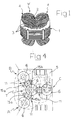
- FIG. 1 A typical known stator of an electric motor is shown in FIG. 1.
- the stator includes an annular body 1 having a laminated structure with an inner cylindrical surface 2 and a plurality of longitudinal slots 3. Longitudinal slots 3 receive portions of copper wire coils 4, which constitute the winding W of the stator.
- Coils 4 are formed in a coiling machine that delivers the formed coils to a coil-inserting tool, such as, for example, the type disclosed in U.S. Patent No. 3,324,536.
- a coil-inserting tool inserts the coils positioned thereon into slots of a stator, which are aligned over the coil-inserting tool.
- Apparatus of the above type is also known that includes first and second coiling stations, an inserting station, and means (typically a platform rotatable around a vertical axis) to bring a coil inserting tool sequentially to the first coiling station, then to the second coiling station, and lastly to the inserting station.
- This apparatus is used, for example, to provide stators of the type shown in FIG. 1.
- stators include a primary winding of two coils 4 arranged as shown in FIG. 1, and a secondary winding of two additional coils arranged at 90 degrees with respect to the primary winding coils.
- the coil-inserting tool receives the first pair of coils for the primary winding at the first coiling station, and the second pair of coils for the secondary winding at the second coiling station. From the second coiling station, the coil-inserting tool is brought to the inserting station where the primary and secondary windings are simultaneously inserted into the stator slots.
- the advantage of two coiling stations is limited, because a single coiling station can form coils for both the primary and secondary stator windings.
- production capacity is limited because the cycle time of forming coils at a coiling station is often longer than the cycle time of inserting the coils at an inserting station. For example, insertion may be approximately 15 seconds, while forming coils may be approximately 30 seconds. Thus, production capacity is limited by the coiling time.
- apparatus and methods for forming coils that are used for the winding of a stator of a dynamo-electric machine and for inserting those coils into slots of the stator includes first and second coiling stations, an inserting station, a transfer station that assists each of the coiling and inserting station, and transfer means for synchronously exchanging coil-inserting tools at each of the assisted station with a coil-inserting tool at the transfer station.
- the present invention produces finished stators with a production capacity substantially equivalent to the production capacity of an inserting station.
- two coiling stations operate on two different coil-inserting tools.
- Each coiling station forms and loads coils (for use as the primary and secondary windings of a stator) onto a coil-inserting tool.
- the coil-inserting tool inserts the coils into a respective stator at an inserting station.
- the two coiling stations operate synchronously with respect to each other. That is, when the first coiling station completes its cycle, the coil-inserting tool, which has been loaded with coils formed at the first coiling station, is transferred to the transfer station and then to the inserting station, where the coils are inserted into a respective stator. Meanwhile, the second coiling station forms and loads another set of coils onto another coil-inserting tool, which is then transferred to the transfer station and to the inserting station as soon as the previous coil-inserting tool at the inserting station has inserted its coils into the respective stator.
- the inserting station is therefore continuously fed with loaded coil-inserting tools by the synchronous operation of the two coiling stations, thus significantly improving production capacity.
- the coiling and inserting stations are equiangularly spaced apart from each other around the transfer station.
- Transfer means for exchanging a coil-inserting tool at each of the coiling and inserting stations with a coil-inserting tool at the transfer station includes a plurality of exchange devices.
- One exchange device is interposed between each of the coiling and inserting stations and the transfer station.
- three exchange devices are provided. Each exchange device exchanges a coil-inserting tool at one station (i.e., a coiling or inserting station) with a coil-inserting tool at the transfer station.
- the exchange devices operate as follows: a first exchange device between a first coiling station and a transfer station exchanges a coil-inserting tool loaded with coils at the first coiling station with an empty coil-inserting tool at the transfer station. A second exchange device between the transfer station and an inserting station then exchanges the loaded first coil-inserting tool with an empty coil-inserting tool at the inserting station. Similarly, a third exchange device between a second coiling station and the transfer station exchanges a coil-inserting tool loaded with coils at the second coiling station with the empty coil-inserting tool at the transfer station. As described below, the transfer of coil-inserting tools between the various stations is advantageously provided with relatively simple and inexpensive means.
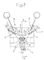
- the apparatus includes a base structure 5 that supports a first coiling station A, a second coiling station B and an inserting station C, which are preferably equiangularly spaced apart from each other around a transfer station T.
- a coil-inserting tool 6 of any known type (such, for example, the type disclosed in the U.S. patent above) is provided to either receive thereon coils formed at either station A or station B, or to insert the coils into slots 3 of a stator positioned at inserting station C.
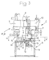
- a column 7 extends upwardly as shown in FIG.
- each exchange device 11 is interposed between each of the three operative stations A, B and C and transfer station T.
- Each exchange device 11 includes a central support 12 rotatably mounted around a central vertical axis 13.
- Central support 12 rotates around axis 13 by a motor 16 to exchange the coil-inserting tools that are respectively located at transfer station T and the operative station (A, B, or C) that is being assisted by central support 12.
- Central support 12 further includes clamps 15a and 15b at opposite ends thereof for grasping horizontal projections 14, which form part of the base of coil-inserting tool 6.
- Clamps 15a and 15b preferably have teeth to engage reference holes in horizontal projections 14 for maintaining the proper position of coil-inserting tool 6 during its transfer by central support 12.
- a raising unit 17 raises central support 12 after clamps 15a and 15b have grasped the respective horizontal projections 14, causing the bases of coil-inserting tools 6 to come out of centering circles 18 provided at the areas where coil-inserting tools 6 are positioned. Once the bases have come out of centering circles 18, central support 12 can be rotated around axis 13. Slots 19 are provided on the bases of coil-inserting tools 6 for receiving reference pins provided at the areas where coil-inserting tools 6 are positioned. These pins engage the sides of slots to ensure proper alignment of coil-inserting tool 6 at each station.
- a brushless motor 20 is provided at transfer station T to rotate a supporting structure where a coil-inserting tool 6 is located.
- Motor 20 rotates the structure and hence coil-inserting tool 6 around an axis 21 by a predetermined angle to provide coil-inserting tool 6 with the proper angular position for receiving the coils from coil-forming head 9 in accordance with the electric specifications for the stator.
- a further rotation of coil-inserting tool 6 by motor 20 brings horizontal projections 14 in alignment with clamps 15a and 15b of central support 12 such that coil-inserting tool 6 can be grasped for the next exchange.
- the apparatus operates as follows: the two coil-forming heads 9 form and load coils 4 onto coil-inserting tools 6 at respective coiling stations A and B.
- the forming and loading cycles of coiling stations A and B are synchronously staggered by approximately one half cycle. That is, at the start of coiling station B's cycle, coiling station A has completed half its cycle.
- the respective exchange device 11 exchanges the loaded coil-inserting tool 6 with an empty coil-inserting tool 6 located at transfer station T.
- the loaded coil-inserting tool 6, now located at transfer station T is then exchanged with an empty coil-inserting tool 6 located at inserting station C.
- the exchange is made by the exchange device 11 between transfer station T and inserting station C. Inserting station C then inserts the loaded coils into a stator positioned at inserting station C. Meanwhile, coiling station B has completed its cycle, and its loaded coil-inserting tool 6 is then exchanged with the empty coil-inserting tool 6 that has been brought from inserting station C to transfer station T. From transfer station T, the loaded coil-inserting tool is then brought to inserting station C for insertion of the loaded coils into another stator.
- inventions may include additional coiling stations. For example, if the cycle time insertion is approximately one third the cycle time of coil forming and loading, three coiling stations operating in a similar synchronously staggered manner with a single inserting station may advantageously be provided.
Landscapes
- Engineering & Computer Science (AREA)
- Manufacturing & Machinery (AREA)
- Power Engineering (AREA)
- Manufacture Of Motors, Generators (AREA)
- Insulation, Fastening Of Motor, Generator Windings (AREA)
Claims (11)
- Appareil de formation de bobines (4) qui sont utilisées pour l'enroulement (W) d'un inducteur (1) d'une machine électrodynamique et en vue de l'insertion desdites bobines (4) dans les encoches (3) dudit inducteur (1), ledit appareil comportant :une pluralité de postes de bobinage (A, B) ;un poste d'insertion (C) ;un poste de transfert (T) assistant chacun desdits postes de bobinage et d'insertion (A, B, C) ; et caractérisé pardes moyens de transfert (11) afin d'échanger un outil d'insertion de bobines (6) en chacun desdits postes de bobinage et d'insertion (A, B, C) contre un autre outil d'insertion de bobines (6) audit poste de transfert (T).
- Appareil selon la revendication 1, dans lequel ladite pluralité de postes de bobinage (A, B) possèdent des cycles de formation et de chargement échelonnés de façon synchrone.
- Appareil selon la revendication 1, dans lequel lesdits postes de bobinage et d'insertion (A, B, C) sont uniformément espacés les uns des autres autour dudit poste de transfert (T).
- Appareil selon la revendication 1, dans lequel lesdits moyens de transfert comportent une pluralité de dispositifs d'échange (11), l'un desdits dispositifs d'échange (11) étant interposé entre chacun desdits postes de bobinage (A, B) et ledit poste de transfert (T) et entre ledit poste de transfert (T) et ledit poste d'insertion (C), chacun desdits dispositifs d'échange (11) échangeant un premier outil d'insertion de bobines (6) contre un second outil d'insertion de bobines (6).
- Appareil selon la revendication 4, dans lequel au moins un desdits dispositifs d'échange (11) comporte un bras (12) monté à rotation autour d'un axe vertical central (13), ledit bras (12) ayant des extrémités opposées munies d'éléments de pincement (15) qui coopèrent avec des éléments de couplage (14) sur lesdits outils d'insertion de bobines (6).
- Appareil selon la revendication 5, dans lequel lesdits éléments de pincement (15) possèdent des dents afin de pénétrer dans lesdits éléments de couplage (14) sur lesdits outils d'insertion de bobines (6).
- Appareil selon la revendication 1, dans lequel au moins l'un desdits postes de bobinage, d'insertion et de transfert (A, B, C, T) comporte des cercles de centrage (18) afin de positionner correctement lesdits outils d'insertion de bobines (6).
- Appareil selon la revendication 1, dans lequel au moins l'un desdits postes de bobinage, d'insertion et de transfert (A, B, C, T) comporte des broches de référence afin d'aligner correctement lesdits outils d'insertion de bobines (6).
- Appareil selon la revendication 1, comportant en outre un moteur afin d'aligner correctement lesdits outils d'insertion de bobines (6) en vue d'un engagement avec lesdits moyens d'échange (11).
- Procédé de formation de bobines (4) qui sont utilisées pour l'enroulement (W) d'un inducteur (1) d'une machine électrodynamique et d'insertion desdites bobines (4) dans des encoches (3) dudit inducteur (1), ledit procédé comportant les étapes consistant à :former des premières bobines (4) en un premier poste de bobinage (A) ;charger lesdites premières bobines (4) sur un premier outil d'insertion de bobines (6) audit premier poste de bobinage (A) ;échanger ledit premier outil d'insertion de bobines (6) contre un troisième outil d'insertion de bobines (6) ;échanger ledit premier outil d'insertion de bobines (6) contre un quatrième outil d'insertion de bobines (6) ;insérer ladite première bobine dans un premier inducteur (1) ;former des secondes bobines (4) en un second poste de bobinages (B) ;charger lesdites secondes bobines (4) sur un second outil d'insertion de bobines (6) audit second poste de bobinage (B) ;échanger ledit second outil d'insertion de bobines (6) contre ledit quatrième outil d'insertion de bobines (6) ;échanger ledit second outil d'insertion de bobines (6) contre ledit premier outil d'insertion de bobines (6) ; etinsérer ladite seconde bobine (4) dans un second inducteur (1).
- Procédé selon la revendication 10, dans lequel lesdites étapes d'échange comportent les étapes consistant à:amener en contact lesdits outils d'insertion de bobines (6) avec des éléments de pincement (15) ;soulever lesdits outils d'insertion de bobines (6) ;faire tourner lesdits outils d'insertion de bobines (6) autour d'un axe central (13) ;abaisser lesdits outils d'insertion de bobines (6) ; etpositionner lesdits outils d'insertion de bobines (6) en alignant des broches de référence avec des structures correspondantes sur lesdits outils d'insertion de bobines (6).
Applications Claiming Priority (2)
| Application Number | Priority Date | Filing Date | Title |
|---|---|---|---|
| ITTO960555 | 1996-06-28 | ||
| IT96TO000555A IT1286133B1 (it) | 1996-06-28 | 1996-06-28 | Apparecchiatura per la formatura e l'inserimento di bobine costituenti l'avvolgimento dello statore di una macchina dinamoelettrica. |
Publications (2)
| Publication Number | Publication Date |
|---|---|
| EP0817357A1 EP0817357A1 (fr) | 1998-01-07 |
| EP0817357B1 true EP0817357B1 (fr) | 2000-03-15 |
Family
ID=11414745
Family Applications (1)
| Application Number | Title | Priority Date | Filing Date |
|---|---|---|---|
| EP97110541A Expired - Lifetime EP0817357B1 (fr) | 1996-06-28 | 1997-06-27 | Dispositif et méthodes de formation et insertion de bobines à plusieurs lobes, constituant les enroulements du stator d'un alternateur |
Country Status (6)
| Country | Link |
|---|---|
| US (1) | US5921288A (fr) |
| EP (1) | EP0817357B1 (fr) |
| CA (1) | CA2208914A1 (fr) |
| DE (1) | DE69701425T2 (fr) |
| ES (1) | ES2145536T3 (fr) |
| IT (1) | IT1286133B1 (fr) |
Families Citing this family (3)
| Publication number | Priority date | Publication date | Assignee | Title |
|---|---|---|---|---|
| US6463721B1 (en) | 2001-07-27 | 2002-10-15 | Su Chi-Jan | Strapping machine with a strap tightening unit |
| ITPI20050048A1 (it) * | 2005-05-10 | 2006-11-11 | Atop Spa | Sistemi per avvolgere e inserire bobine in componenti di macchine dinamoelettriche |
| DE102010010068B4 (de) * | 2010-03-03 | 2012-10-04 | Festo Ag & Co. Kg | Elektromagnetischer Lineardirektantrieb |
Family Cites Families (6)
| Publication number | Priority date | Publication date | Assignee | Title |
|---|---|---|---|---|
| US3324536A (en) * | 1965-05-03 | 1967-06-13 | Donald E Hill | Coil assembling apparatus |
| US3579818A (en) * | 1969-03-11 | 1971-05-25 | Gen Electric | Method and apparatus for forming shaped insulators and for developing coils of a magnetic core |
| JPS5389901A (en) * | 1977-01-18 | 1978-08-08 | Matsushita Electric Ind Co Ltd | Stator manufacturing method its device for electrical machinery |
| US4151636A (en) * | 1977-12-05 | 1979-05-01 | General Electric Company | Injection shuttle system |
| US4512376A (en) * | 1983-07-08 | 1985-04-23 | Giorgio Barrera | Apparatus for forming stator coils of dynamo electric machines |
| US4658492A (en) * | 1984-12-21 | 1987-04-21 | Emerson Electric Co. | Coil assembly machine |
-
1996
- 1996-06-28 IT IT96TO000555A patent/IT1286133B1/it active IP Right Grant
-
1997
- 1997-06-18 US US08/878,465 patent/US5921288A/en not_active Expired - Lifetime
- 1997-06-27 ES ES97110541T patent/ES2145536T3/es not_active Expired - Lifetime
- 1997-06-27 CA CA002208914A patent/CA2208914A1/fr not_active Abandoned
- 1997-06-27 DE DE69701425T patent/DE69701425T2/de not_active Expired - Lifetime
- 1997-06-27 EP EP97110541A patent/EP0817357B1/fr not_active Expired - Lifetime
Also Published As
| Publication number | Publication date |
|---|---|
| US5921288A (en) | 1999-07-13 |
| DE69701425D1 (de) | 2000-04-20 |
| ITTO960555A1 (it) | 1997-12-28 |
| ES2145536T3 (es) | 2000-07-01 |
| DE69701425T2 (de) | 2000-12-14 |
| CA2208914A1 (fr) | 1997-12-28 |
| IT1286133B1 (it) | 1998-07-07 |
| ITTO960555A0 (fr) | 1996-06-28 |
| EP0817357A1 (fr) | 1998-01-07 |
Similar Documents
| Publication | Publication Date | Title |
|---|---|---|
| CN100395946C (zh) | 线圈形成装置以及线圈形成方法 | |
| JP3718530B2 (ja) | 回転電気機械用電機子を製造するための方法及び装置 | |
| EP0209162B1 (fr) | Ligne de production pour stators de moteur électrique montés sur palettes | |
| US7498709B2 (en) | Method and apparatus for winding segments of a segmented wound member of an electromechanical device | |
| CN100477453C (zh) | 绕线装置和方法 | |
| EP0817357B1 (fr) | Dispositif et méthodes de formation et insertion de bobines à plusieurs lobes, constituant les enroulements du stator d'un alternateur | |
| US7380335B2 (en) | Stator manufacturing device | |
| EP1609231B1 (fr) | Appareil et procedes pour le placement de conducteurs de boucles en fil | |
| JP2003319622A (ja) | 回転電機用固定子コイルの製造方法および製造装置 | |
| JP3783660B2 (ja) | 回転電機のセグメント順次接合ステータコイル | |
| JPH01228740A (ja) | 発電機のステータの空洞内に複数の位相絶縁体を挿入する方法および装置 | |
| JP2004173403A (ja) | 回転電機の電機子及びその製造方法 | |
| EP0359297B1 (fr) | Méthode et appareil pour bobiner les stators bipolaires de moteur électrique | |
| WO1997042698A9 (fr) | Appareil et procede d'enroulement de stator | |
| WO1997042698A1 (fr) | Appareil et procede d'enroulement de stator | |
| JPH06303748A (ja) | 波形状巻線製造方法および波形状巻線製造装置 | |
| JPS59162742A (ja) | 鉄心内に中間絶縁体を配置するための方法及び装置 | |
| JP3774025B2 (ja) | 固定子コイル挿入装置 | |
| EP0818874A1 (fr) | Dispositif et méthodes de formation et insertion de bobines à plusieurs lobes, constituantes les enroulements du stator d'un alternateur | |
| US4117707A (en) | Apparatus for shaping electrical coils for dynamoelectric machines | |
| JP3140656B2 (ja) | 巻線方法 | |
| JP3514948B2 (ja) | 回転電機用ステータ及びその製造方法 | |
| JP2003333809A5 (fr) | ||
| JPS5939982B2 (ja) | 相間絶縁物插入装置 | |
| KR102825075B1 (ko) | 모터 고정자 코일 절단 장치 |
Legal Events
| Date | Code | Title | Description |
|---|---|---|---|
| PUAI | Public reference made under article 153(3) epc to a published international application that has entered the european phase |
Free format text: ORIGINAL CODE: 0009012 |
|
| AK | Designated contracting states |
Kind code of ref document: A1 Designated state(s): CH DE ES FR GB IT LI SE |
|
| 17P | Request for examination filed |
Effective date: 19980211 |
|
| AKX | Designation fees paid |
Free format text: CH DE ES FR GB IT LI SE |
|
| RBV | Designated contracting states (corrected) |
Designated state(s): CH DE ES FR GB IT LI SE |
|
| GRAG | Despatch of communication of intention to grant |
Free format text: ORIGINAL CODE: EPIDOS AGRA |
|
| GRAG | Despatch of communication of intention to grant |
Free format text: ORIGINAL CODE: EPIDOS AGRA |
|
| GRAH | Despatch of communication of intention to grant a patent |
Free format text: ORIGINAL CODE: EPIDOS IGRA |
|
| 17Q | First examination report despatched |
Effective date: 19990426 |
|
| GRAH | Despatch of communication of intention to grant a patent |
Free format text: ORIGINAL CODE: EPIDOS IGRA |
|
| GRAA | (expected) grant |
Free format text: ORIGINAL CODE: 0009210 |
|
| AK | Designated contracting states |
Kind code of ref document: B1 Designated state(s): CH DE ES FR GB IT LI SE |
|
| PG25 | Lapsed in a contracting state [announced via postgrant information from national office to epo] |
Ref country code: SE Free format text: THE PATENT HAS BEEN ANNULLED BY A DECISION OF A NATIONAL AUTHORITY Effective date: 20000315 Ref country code: LI Free format text: LAPSE BECAUSE OF NON-PAYMENT OF DUE FEES Effective date: 20000315 Ref country code: CH Free format text: LAPSE BECAUSE OF NON-PAYMENT OF DUE FEES Effective date: 20000315 |
|
| REG | Reference to a national code |
Ref country code: CH Ref legal event code: EP |
|
| REF | Corresponds to: |
Ref document number: 69701425 Country of ref document: DE Date of ref document: 20000420 |
|
| ITF | It: translation for a ep patent filed | ||
| RAP2 | Party data changed (patent owner data changed or rights of a patent transferred) |
Owner name: PAVESI S.R.L. |
|
| REG | Reference to a national code |
Ref country code: ES Ref legal event code: FG2A Ref document number: 2145536 Country of ref document: ES Kind code of ref document: T3 |
|
| ET | Fr: translation filed | ||
| REG | Reference to a national code |
Ref country code: CH Ref legal event code: PL |
|
| REG | Reference to a national code |
Ref country code: FR Ref legal event code: CD |
|
| PLBE | No opposition filed within time limit |
Free format text: ORIGINAL CODE: 0009261 |
|
| STAA | Information on the status of an ep patent application or granted ep patent |
Free format text: STATUS: NO OPPOSITION FILED WITHIN TIME LIMIT |
|
| 26N | No opposition filed | ||
| REG | Reference to a national code |
Ref country code: GB Ref legal event code: IF02 |
|
| PGFP | Annual fee paid to national office [announced via postgrant information from national office to epo] |
Ref country code: GB Payment date: 20050622 Year of fee payment: 9 |
|
| PGFP | Annual fee paid to national office [announced via postgrant information from national office to epo] |
Ref country code: ES Payment date: 20050728 Year of fee payment: 9 |
|
| PG25 | Lapsed in a contracting state [announced via postgrant information from national office to epo] |
Ref country code: GB Free format text: LAPSE BECAUSE OF NON-PAYMENT OF DUE FEES Effective date: 20060627 |
|
| PG25 | Lapsed in a contracting state [announced via postgrant information from national office to epo] |
Ref country code: ES Free format text: LAPSE BECAUSE OF NON-PAYMENT OF DUE FEES Effective date: 20060628 |
|
| GBPC | Gb: european patent ceased through non-payment of renewal fee |
Effective date: 20060627 |
|
| REG | Reference to a national code |
Ref country code: ES Ref legal event code: FD2A Effective date: 20060628 |
|
| REG | Reference to a national code |
Ref country code: FR Ref legal event code: PLFP Year of fee payment: 19 |
|
| PGFP | Annual fee paid to national office [announced via postgrant information from national office to epo] |
Ref country code: DE Payment date: 20150623 Year of fee payment: 19 |
|
| PGFP | Annual fee paid to national office [announced via postgrant information from national office to epo] |
Ref country code: FR Payment date: 20150623 Year of fee payment: 19 Ref country code: IT Payment date: 20150617 Year of fee payment: 19 |
|
| REG | Reference to a national code |
Ref country code: DE Ref legal event code: R119 Ref document number: 69701425 Country of ref document: DE |
|
| REG | Reference to a national code |
Ref country code: FR Ref legal event code: ST Effective date: 20170228 |
|
| PG25 | Lapsed in a contracting state [announced via postgrant information from national office to epo] |
Ref country code: DE Free format text: LAPSE BECAUSE OF NON-PAYMENT OF DUE FEES Effective date: 20170103 Ref country code: FR Free format text: LAPSE BECAUSE OF NON-PAYMENT OF DUE FEES Effective date: 20160630 |
|
| PG25 | Lapsed in a contracting state [announced via postgrant information from national office to epo] |
Ref country code: IT Free format text: LAPSE BECAUSE OF NON-PAYMENT OF DUE FEES Effective date: 20160627 |