EP0817363A2 - Méthode d'entraínement électromagnétique et appareil pour entraíner un objet levité magnétiquement et stabilisé en rotation - Google Patents
Méthode d'entraínement électromagnétique et appareil pour entraíner un objet levité magnétiquement et stabilisé en rotation Download PDFInfo
- Publication number
- EP0817363A2 EP0817363A2 EP97110287A EP97110287A EP0817363A2 EP 0817363 A2 EP0817363 A2 EP 0817363A2 EP 97110287 A EP97110287 A EP 97110287A EP 97110287 A EP97110287 A EP 97110287A EP 0817363 A2 EP0817363 A2 EP 0817363A2
- Authority
- EP
- European Patent Office
- Prior art keywords
- magnet
- magnetic field
- coil
- spindle
- pulsed
- Prior art date
- Legal status (The legal status is an assumption and is not a legal conclusion. Google has not performed a legal analysis and makes no representation as to the accuracy of the status listed.)
- Withdrawn
Links
Images

Classifications
-
- F—MECHANICAL ENGINEERING; LIGHTING; HEATING; WEAPONS; BLASTING
- F16—ENGINEERING ELEMENTS AND UNITS; GENERAL MEASURES FOR PRODUCING AND MAINTAINING EFFECTIVE FUNCTIONING OF MACHINES OR INSTALLATIONS; THERMAL INSULATION IN GENERAL
- F16C—SHAFTS; FLEXIBLE SHAFTS; ELEMENTS OR CRANKSHAFT MECHANISMS; ROTARY BODIES OTHER THAN GEARING ELEMENTS; BEARINGS
- F16C32/00—Bearings not otherwise provided for
- F16C32/04—Bearings not otherwise provided for using magnetic or electric supporting means
- F16C32/0406—Magnetic bearings
- F16C32/0408—Passive magnetic bearings
- F16C32/0436—Passive magnetic bearings with a conductor on one part movable with respect to a magnetic field, e.g. a body of copper on one part and a permanent magnet on the other part
-
- H—ELECTRICITY
- H02—GENERATION; CONVERSION OR DISTRIBUTION OF ELECTRIC POWER
- H02K—DYNAMO-ELECTRIC MACHINES
- H02K99/00—Subject matter not provided for in other groups of this subclass
- H02K99/20—Motors
-
- H—ELECTRICITY
- H02—GENERATION; CONVERSION OR DISTRIBUTION OF ELECTRIC POWER
- H02N—ELECTRIC MACHINES NOT OTHERWISE PROVIDED FOR
- H02N15/00—Holding or levitation devices using magnetic attraction or repulsion, not otherwise provided for
-
- Y—GENERAL TAGGING OF NEW TECHNOLOGICAL DEVELOPMENTS; GENERAL TAGGING OF CROSS-SECTIONAL TECHNOLOGIES SPANNING OVER SEVERAL SECTIONS OF THE IPC; TECHNICAL SUBJECTS COVERED BY FORMER USPC CROSS-REFERENCE ART COLLECTIONS [XRACs] AND DIGESTS
- Y10—TECHNICAL SUBJECTS COVERED BY FORMER USPC
- Y10T—TECHNICAL SUBJECTS COVERED BY FORMER US CLASSIFICATION
- Y10T74/00—Machine element or mechanism
- Y10T74/12—Gyroscopes
- Y10T74/1282—Gyroscopes with rotor drive
Definitions
- the smaller magnet has an annular or ring shape with a non-magnetic spindle fitted into the central hole thereof, the combination thus resembling a toy top.
- the system is operated by first placing a sheet of nonmagnetic material such as a plastic sheet on the lower magnet.
- the top is pressed gently against the plastic sheet and is set spinning either manually or with a mechanical device.
- the plastic sheet, bearing the spinning top is then manually lifted upwardly.
- the top reaches a certain height above the lower magnet (usually about one to four inches), it rises off the plastic sheet and remains spinning stably in space, supported only by the force from the interacting magnetic fields of the two magnets.
- the top will continue to spin for several minutes, its rotational speed gradually decreasing due to air drag. When the speed falls below that required to maintain stability, the top flips over and falls to the lower magnet.
- the manifold is supported in such a way that the jet outlets or nozzles are arrayed in a circle about the spinning top and in a horizontal plane at the levitating height of the top.
- the air nozzles are directed in the horizontal plane of the top and the air streams projected in this plane have both tangential and radial components relative to the periphery and spin axis of the top, respectively.
- the top periphery is preferably provided with reaction surfaces, such as vanes, protuberances, roughened surfaces or the like. Such surfaces react with the air streams coming from the air nozzles and transfer the linear momentum of the air streams to angular momentum of the top, thus maintaining the rotational velocity of the top against air drag.
- a flat base magnet is magnetized such that the field lines of its magnetic field are substantially perpendicular to the flat surfaces of the base magnet and the magnet of the spinning top is magnetized such that the field lines of its main magnetic field are substantially parallel to the spin axis of the spinning top.
- a horizontal component of a magnetic field is located in the region of the spinning top and is pulsed at a selected repetition rate of about 15-30 pulses per second (pps), or at multiples of the selected repetition rate, e.g., 20 pps or 40 pps.
- the pulsed magnetic field is preferably achieved by locating one or more conductive wire coils in an appropriate position or positions with respect to the magnet of the spinning top so that when a pulsed dc voltage is applied to the coil a pulsed horizontal field is generated at the spinning top.
- the pulsed magnetic field may be applied before or after the top is spun either manually or by any other means.
- the spinning top is subjected to the horizontal component of the pulsed magnetic field at a pulse repetition rate less than the spin rate.
- the top will couple to the pulsed magnetic field generated by the coil or coils. It has been found that the spin rate typically does not couple to the pulse rate at a ratio of 1:1 or 1:2.
- the spinning top will couple to the field at a spin rate of about 30 cps (1800 rpm) and will spin at substantially that rate indefinitely or for an extended period of time. It has also been found that coupling does not appear to be possible if the pulse rate of the magnetic field is greater than the rate at which coupling occurs for a given spin rate of the top unless the pulse rate is a multiple of the coupling pulse rate.
- the pulsed field does not appear to be capable of increasing the spin rate of the top to achieve coupling so that coupling appears to occur only when the spin rate of the top decreases to that spin rate required for coupling at a given pulse rate or a multiple of the coupling pulse rate.
- the above-described phenomenon is believed to occur for the following reason.
- the magnet of the spinning top attempts to align itself with the horizontal component of the induced magnetic field of the coil each time the field is energized, i.e., pulsed.
- This attempted alignment produces a net force or torque on the spinning top about its spin axis when the spin rate of the top is coupled or synchronized with the pulsed induced magnetic field.
- the ratio between the pulse rate and the spin rate when the top is coupled to the pulsed field varies both with the pulse rate and the strength of the horizontal field at the top.
- the spin rate is approximately 1.25 to 1.5 times the lowest coupling pulse rate.
- the spin rate will be a lower percentage of the pulse rate, e.g., about .6 to .75 times the first multiple of the lowest coupling pulse rate.
- the magnetic field which generates the horizontal field component at the spinning top may be provided in a number of ways.
- a conductor wire may be wrapped about the base magnet with the axes of the windings oriented along any horizontal axis.
- a coil or coils may be disposed above or below the base magnet or in a central opening thereof (if such opening is provided in the base magnet) or above the location of the spinning levitated top with the axis or axes of the field or fields generated thereby arranged along a horizontal axis or axes at any angular orientation with respect to the local vertical.
- the coil is provided with an iron core which is preferably in the form of a flat sheet material with a rectangular perimeter.
- the coil is preferably wrapped about the core sheet so as to have a relatively flattened shape rather than a cylindrical shape.
- such coil/core configuration minimizes the height of the core/coil arrangement and makes possible a compact combination with the base magnet.
- the iron core substantially improves the horizontal orientation of the pulsed magnetic field at the spinning top.
- the coil may be wrapped about the rectangular core sheet substantially at a central portion thereof, but is preferably wrapped about the core from end-to-end so as to substantially enclose the core sheet in the wire coil. This latter form of core/coil structure provides a further improvement in the horizontal orientation of the pulsed magnetic field than a coil located about the central portion of the core sheet.
- the coil (or coils as the case may be) is periodically energized or pulsed by applying a dc current pulse to the coil at a given pulse repetition rate, e.g., 15 pps, or a low frequency ac current, e.g., 15-20 Hertz.
- System 10 comprises a base magnet 12 which may have a polygonal, square or circular periphery and a central circular opening (not shown).
- the magnet 12 has planar upper and lower surfaces 14, 16, respectively, and is polarized or magnetized perpendicular to those surfaces.
- a top 18 comprises a disk magnet or a flat ring magnet 20 polarized or magnetized oppositely to base magnet 12 perpendicular to its upper and lower surfaces 22, 24, respectively.
- a nonmagnetic spindle 26 passes through a central opening (not shown) in the ring magnet 20 and is used to manually spin the top about a vertical axis. It is to be understood that the top may be spun by means other than manually. If the magnet 20 is a disk, the spindle may be attached to the surface of the magnet along the axis thereof.
- FIG. 3 illustrates yet another embodiment of the system of the invention represented generally by reference numeral 60.
- System 60 includes a base magnet 62 which is used to levitate spinning top 64.
- a coil 66 is disposed above the top 64 with its axis C in a horizontal plane.
- Coil 66 has terminals 68, 70 to which a pulsed dc voltage V may be applied to generate a pulsed magnetic field represented by flux lines G.
- Field F has a horizontal component at the top 64 which maintains the top spinning indefinitely or for an extended period of time at a substantially constant speed in the manner described above.
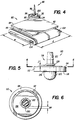
- FIG. 4 illustrates yet another embodiment of the invention comprising a continuously levitating spinning magnet system designated generally by reference numeral 80.
- System 80 comprises a base magnet 82 which may have a square or circular periphery and a central circular opening (not shown).
- the magnet 82 has planar upper and lower surfaces 84, 86, respectively, and is polarized or magnetized perpendicular to those surfaces.
- a top 88 comprises a flat ring magnet 90 polarized or magnetized oppositely to base magnet 82 perpendicular to its upper and lower surfaces 92, 94, respectively.
- a nonmagnetic spindle 96 passes through a central opening (not shown) in the ring magnet 90 and is used to manually spin the top about a vertical axis.
- a coil 102 with a ferrous metal core 104 preferably in the form of a square or rectangular sheet of iron, although other perimetrical shapes are possible.
- the coil 102 has an oblong or substantially flattened shape as compared with the cylindrical coil 46 shown in FIG. 2 and may be formed by wrapping the coil wire or winding about the width w of core 104 from side to side. It has been found that it is advantageous for the coil 102 to extend substantially the entire length l of the core 104 from end to end.
- coil or coil/core arrangements may be used to generate the required pulsed horizontal field at the spinning top. Such arrangements will be apparent to one of ordinary skill in the art in light of the description herein. It will also be apparent in view of this description that the angular orientation or azimuth of the axis of the horizontal field at the spinning magnet is not critical and may be selected at random. In other words, the axis of the coil/core combination of FIG. 4, for example, may be oriented at any azimuth angle about the vertical axis of the spinning top.
- the pulsed horizontal field at the spinning magnet need not be pulsed with a voltage between a zero magnitude and a positive or negative voltage magnitude, but may be pulsed with voltages of two different strengths of positive or negative voltage.
- the magnitude and pulse width of the voltage to be applied to the coil which generates the horizontal field will vary depending on a number of factors, such as coil location, number of turns, wire size, the particular designs and sizes of the base magnet and the ring magnet of the top, whether or not a core is used with the coil and other factors. It has been found that adjustment of the voltage magnitude and pulse width to achieve indefinite levitation of the spinning top is relatively easy to accomplish in light of the teachings herein.
- top 110 is formed with a flat ring or disk magnet 112 with upper and lower planar surfaces 114, 116, respectively.
- a non-magnetic spindle 118 passes through the central opening in the ring magnet and is secured therein by any suitable means, e.g., adhesive, interference fit, etc.
- the lower portion 120 of the spindle 118 has a larger diameter than the upper portion 122 thereof so as to form a shoulder 124 upon which the ring magnet 112 rests.
- This structure is one of many possible arrangements for supporting the magnet on the spindle.
- the spindle portions 120, 122 may be bonded to the surfaces of the magnet along the spin axis thereof.
- a washer 126 is placed on the spindle 118 to adjust the weight of the top 110 for optimum levitation performance and is held in place by a rubber grommet or O-ring 128, or other suitable means.
- the washer 126 is made of a non-magnetic material, such as brass, copper, a non-magnetic stainless steel alloy or other non-magnetic material.
- the central bore 130 of the washer 126 is somewhat larger in diameter than the diameter of the upper portion 122 of the spindle 118 about which the washer is located. The difference in diameters is depicted in FIG. 6 as dimension ⁇ d which is not necessarily to scale.
- the washer 126 is shown held in place on the spindle 118 by the O-ring 128, but with a sufficient clearance c so that the O-ring does not prevent the washer from rotating and moving radially relative to the spindle portion 122 and magnet 112.
- the above-described arrangement or structure of the washer, spindle and O-ring components of the spinning top substantially improves the stability and thus the longevity of levitation of the spinning top when used in combination with one of the pulsed magnetic fields described herein. It has been observed stroboscopically that the washer 126 rotates slightly faster than the spinning top and that the washer slides radially in a wobbling or "orbiting" fashion about the spindle 118 as depicted illustratively in broken lines in FIG. 6 . The wobbling motion of the washer has also been accompanied by a chattering sound emitted by reason of the washer motion. When the O-ring 128 is pushed down tightly onto the washer so as to eliminate the clearance c and prevent the wobbling movement of the washer about the spindle, the stability of the spinning top decreases.
- a particularly advantageous magnetic material for the magnets of the present invention is a neodymium-iron-boron (Nd-Fe-B) magnet of the type described, for example, in U.S. Patent No. 5,213,703.
- a magnetically levitated object can be rotated for an indefinite period of time.
- the object such as a spinning magnetic top with a spindle
- a horizontal component of a pulsed magnetic field is applied at the region of the spinning magnetic top to maintain the top spinning and levitating indefinitely.
- the pulsed magnetic field is generated by applying a pulsed dc voltage or an ac current to a coil situated in proximity to the top.
- the coil may have a cylindrical or oblong shape and a core may be provided in the coil.
- Levitation stability and duration are improved by positioning a loosely fitting washer on the spindle of the spinning magnet so as to permit relative rotation there between during application of the pulsed magnetic field.
Landscapes
- Engineering & Computer Science (AREA)
- General Engineering & Computer Science (AREA)
- Mechanical Engineering (AREA)
- Power Engineering (AREA)
- Chemical & Material Sciences (AREA)
- Combustion & Propulsion (AREA)
- Magnetic Bearings And Hydrostatic Bearings (AREA)
- Linear Motors (AREA)
- Spinning Or Twisting Of Yarns (AREA)
- Magnetic Treatment Devices (AREA)
Applications Claiming Priority (4)
| Application Number | Priority Date | Filing Date | Title |
|---|---|---|---|
| US67267296A | 1996-06-28 | 1996-06-28 | |
| US672672 | 1996-06-28 | ||
| US08/803,027 US5883454A (en) | 1996-06-28 | 1997-02-19 | Electormagnetic drive method and apparatus for driving a rotationally stabilized magnetically levitated object |
| US803027 | 1997-02-19 |
Publications (2)
| Publication Number | Publication Date |
|---|---|
| EP0817363A2 true EP0817363A2 (fr) | 1998-01-07 |
| EP0817363A3 EP0817363A3 (fr) | 1998-04-15 |
Family
ID=27100801
Family Applications (1)
| Application Number | Title | Priority Date | Filing Date |
|---|---|---|---|
| EP97110287A Withdrawn EP0817363A3 (fr) | 1996-06-28 | 1997-06-24 | Méthode d'entraínement électromagnétique et appareil pour entraíner un objet levité magnétiquement et stabilisé en rotation |
Country Status (6)
| Country | Link |
|---|---|
| US (1) | US5883454A (fr) |
| EP (1) | EP0817363A3 (fr) |
| JP (1) | JPH1084684A (fr) |
| CN (1) | CN1171605A (fr) |
| CA (1) | CA2207537A1 (fr) |
| TW (1) | TW355870B (fr) |
Cited By (1)
| Publication number | Priority date | Publication date | Assignee | Title |
|---|---|---|---|---|
| EP2884654A4 (fr) * | 2012-08-09 | 2015-08-12 | Japan Science & Tech Agency | Moteur de spin et élément de rotation de spin |
Families Citing this family (45)
| Publication number | Priority date | Publication date | Assignee | Title |
|---|---|---|---|---|
| US6281608B1 (en) * | 1997-04-16 | 2001-08-28 | Kabushiki Kaisha Sankyo Seiki Seisakusho | Spindle motor and turn table assembly having structure for canceling unbalanced centrifugal force |
| WO2001029803A1 (fr) * | 1999-10-18 | 2001-04-26 | French William W | Dispositif spherique d'affichage auto-rotatif |
| CN2492695Y (zh) * | 2001-07-31 | 2002-05-22 | 孙杜华 | 磁悬浮无刷直流风扇马达 |
| ES2199084B1 (es) * | 2002-07-30 | 2005-06-01 | Advanced Dynamics, S.A | Motor magnetico dinamico de reducido consumo. |
| US20040140875A1 (en) * | 2003-01-22 | 2004-07-22 | Strom Carl H. | Unipolar magnetic system |
| AU2003901696A0 (en) | 2003-04-09 | 2003-05-01 | Cochlear Limited | Implant magnet system |
| US6799462B1 (en) * | 2003-06-05 | 2004-10-05 | International Business Machines Corporation | Gravimetric measurement method and system |
| US7429259B2 (en) * | 2003-12-02 | 2008-09-30 | Cadeddu Jeffrey A | Surgical anchor and system |
| WO2005104977A1 (fr) * | 2004-04-15 | 2005-11-10 | Smith & Nephew, Inc. | Cadre de reference pouvant etre rapidement deconnecte et repositionne pour chirurgie assistee par ordinateur |
| EP2012697A4 (fr) * | 2006-04-29 | 2010-07-21 | Univ Texas | Dispositif destiné à être utilisé dans la chirurgie transluminale et endoluminale |
| CN101083447B (zh) * | 2006-06-01 | 2012-07-25 | 田景华 | 广义施力磁体与使用该磁体的导体轨道磁悬浮车辆或列车 |
| WO2008095003A2 (fr) * | 2007-01-31 | 2008-08-07 | Hadasit Medical Research Services And Development Ltd. | Dispositifs à base de sustentation magnétique, systèmes et techniques pour sondage et fonctionnement dans un espace confiné, comprenant la réalisation de procédures de diagnostic médical et chirurgicales |
| US8500509B2 (en) * | 2007-08-17 | 2013-08-06 | Juan Carlos OROZCO | Entertainment device including a remote controlled magnetic mini-craft |
| US8803646B2 (en) * | 2008-01-22 | 2014-08-12 | George Farber | System and method for magnetic levitation with tilted orientation |
| US8258663B2 (en) * | 2009-09-28 | 2012-09-04 | Disney Enterprises, Inc. | Magnetic levitation novelty device |
| US20110087224A1 (en) * | 2009-10-09 | 2011-04-14 | Cadeddu Jeffrey A | Magnetic surgical sled with variable arm |
| US10172669B2 (en) | 2009-10-09 | 2019-01-08 | Ethicon Llc | Surgical instrument comprising an energy trigger lockout |
| GB2480498A (en) | 2010-05-21 | 2011-11-23 | Ethicon Endo Surgery Inc | Medical device comprising RF circuitry |
| US9421060B2 (en) | 2011-10-24 | 2016-08-23 | Ethicon Endo-Surgery, Llc | Litz wire battery powered device |
| US9827504B2 (en) | 2012-05-19 | 2017-11-28 | Kenneth E. Olson | Vibratory device for bobble toys |
| US9795894B2 (en) * | 2013-08-12 | 2017-10-24 | Joseph Chieffo | Magnetic levitation device and method |
| US10099151B2 (en) * | 2014-05-29 | 2018-10-16 | Owen S. G. Liang | Spin axis controllable spinning top assembly |
| US10159524B2 (en) | 2014-12-22 | 2018-12-25 | Ethicon Llc | High power battery powered RF amplifier topology |
| US10232249B2 (en) | 2015-02-12 | 2019-03-19 | Geeknet, Inc. | Building brick game using magnetic levitation |
| US10314638B2 (en) | 2015-04-07 | 2019-06-11 | Ethicon Llc | Articulating radio frequency (RF) tissue seal with articulating state sensing |
| US10959771B2 (en) | 2015-10-16 | 2021-03-30 | Ethicon Llc | Suction and irrigation sealing grasper |
| US10959806B2 (en) | 2015-12-30 | 2021-03-30 | Ethicon Llc | Energized medical device with reusable handle |
| CN105857647B (zh) * | 2016-03-25 | 2018-06-29 | 西北工业大学 | 低速自旋空间非磁化金属碎片的加速消旋磁场的产生方法 |
| US10987156B2 (en) | 2016-04-29 | 2021-04-27 | Ethicon Llc | Electrosurgical instrument with electrically conductive gap setting member and electrically insulative tissue engaging members |
| US10856934B2 (en) | 2016-04-29 | 2020-12-08 | Ethicon Llc | Electrosurgical instrument with electrically conductive gap setting and tissue engaging members |
| US10751117B2 (en) | 2016-09-23 | 2020-08-25 | Ethicon Llc | Electrosurgical instrument with fluid diverter |
| US11033325B2 (en) | 2017-02-16 | 2021-06-15 | Cilag Gmbh International | Electrosurgical instrument with telescoping suction port and debris cleaner |
| US10799284B2 (en) | 2017-03-15 | 2020-10-13 | Ethicon Llc | Electrosurgical instrument with textured jaws |
| US11497546B2 (en) | 2017-03-31 | 2022-11-15 | Cilag Gmbh International | Area ratios of patterned coatings on RF electrodes to reduce sticking |
| US10603117B2 (en) | 2017-06-28 | 2020-03-31 | Ethicon Llc | Articulation state detection mechanisms |
| US11490951B2 (en) | 2017-09-29 | 2022-11-08 | Cilag Gmbh International | Saline contact with electrodes |
| US11033323B2 (en) | 2017-09-29 | 2021-06-15 | Cilag Gmbh International | Systems and methods for managing fluid and suction in electrosurgical systems |
| US11484358B2 (en) | 2017-09-29 | 2022-11-01 | Cilag Gmbh International | Flexible electrosurgical instrument |
| CN107441720A (zh) * | 2017-10-13 | 2017-12-08 | 王沛卓 | 一种掌上磁悬浮陀螺 |
| CN209856847U (zh) * | 2018-11-20 | 2019-12-27 | 广州树德科技股份有限公司 | 灯具 |
| US12471982B2 (en) | 2020-12-02 | 2025-11-18 | Cilag Gmbh International | Method for tissue treatment by surgical instrument |
| US12508021B2 (en) | 2021-11-01 | 2025-12-30 | Cilag Gmbh International | Devices, systems, and methods for detecting tissue and foreign objects during a surgical operation |
| US11957342B2 (en) | 2021-11-01 | 2024-04-16 | Cilag Gmbh International | Devices, systems, and methods for detecting tissue and foreign objects during a surgical operation |
| CN114132537B (zh) * | 2021-12-01 | 2022-06-07 | 中国科学院空间应用工程与技术中心 | 空间微重力双层悬浮隔振装置、科学实验柜以及悬浮方法 |
| CN115232999B (zh) * | 2022-07-19 | 2023-03-14 | 西北工业大学 | 一种电磁悬浮材料制备方法与系统 |
Family Cites Families (14)
| Publication number | Priority date | Publication date | Assignee | Title |
|---|---|---|---|---|
| US2691306A (en) * | 1951-01-30 | 1954-10-12 | Jesse W Beams | Magnetically supported rotating bodies |
| FR1595792A (fr) * | 1968-11-28 | 1970-06-15 | ||
| US4382245A (en) * | 1978-04-25 | 1983-05-03 | Harrigan Roy Major | Levitation device |
| US4427960A (en) * | 1982-12-06 | 1984-01-24 | Wuerfel Robert P | Magnetic holder for small articles |
| US5213703A (en) * | 1990-02-09 | 1993-05-25 | Matsushita Electric Industrial Co., Ltd. | Anisotropic neodymium-iron-boron system plastic bonded magnet |
| US5019738A (en) * | 1990-07-16 | 1991-05-28 | Lincoln Laser Company | Self-pressurizing gas supported surface-roughness bearing |
| US5177387A (en) * | 1990-12-04 | 1993-01-05 | University Of Houston-University Park | High temperature superconducting magnetic bearings |
| US5168183A (en) * | 1991-03-27 | 1992-12-01 | The University Of British Columbia | Levitation system with permanent magnets and coils |
| US5321986A (en) * | 1992-08-21 | 1994-06-21 | Alliedsignal Inc. | Polar loop implementation for a two degree of freedom gyro |
| US5396136A (en) * | 1992-10-28 | 1995-03-07 | Sri International | Magnetic field levitation |
| US5481146A (en) * | 1993-09-10 | 1996-01-02 | Park Square, Inc. | Passive null flux coil magnetic bearing system for translation or rotation |
| US5404062A (en) * | 1994-02-17 | 1995-04-04 | Creative Gifts, Inc. | Magnetic levitation device and method |
| DE4409992A1 (de) * | 1994-03-23 | 1995-09-28 | Skf Textilmasch Komponenten | Einzelmotorischer Antrieb eines schaftlosen Spinnrotors einer Offenend-Spinnmaschine |
| US5506459A (en) * | 1995-09-15 | 1996-04-09 | Ritts; Gary | Magnetically balanced spinning apparatus |
-
1997
- 1997-02-19 US US08/803,027 patent/US5883454A/en not_active Expired - Fee Related
- 1997-06-12 CA CA002207537A patent/CA2207537A1/fr not_active Abandoned
- 1997-06-20 JP JP9164789A patent/JPH1084684A/ja active Pending
- 1997-06-24 EP EP97110287A patent/EP0817363A3/fr not_active Withdrawn
- 1997-06-27 TW TW086109002A patent/TW355870B/zh active
- 1997-06-27 CN CN97113532A patent/CN1171605A/zh active Pending
Cited By (2)
| Publication number | Priority date | Publication date | Assignee | Title |
|---|---|---|---|---|
| EP2884654A4 (fr) * | 2012-08-09 | 2015-08-12 | Japan Science & Tech Agency | Moteur de spin et élément de rotation de spin |
| US9548634B2 (en) | 2012-08-09 | 2017-01-17 | Japan Science And Technology Agency | Spin motor and rotary member |
Also Published As
| Publication number | Publication date |
|---|---|
| JPH1084684A (ja) | 1998-03-31 |
| TW355870B (en) | 1999-04-11 |
| EP0817363A3 (fr) | 1998-04-15 |
| CA2207537A1 (fr) | 1997-12-28 |
| US5883454A (en) | 1999-03-16 |
| CN1171605A (zh) | 1998-01-28 |
Similar Documents
| Publication | Publication Date | Title |
|---|---|---|
| US5883454A (en) | Electormagnetic drive method and apparatus for driving a rotationally stabilized magnetically levitated object | |
| US5404062A (en) | Magnetic levitation device and method | |
| US7505243B2 (en) | Magnetic levitation apparatus | |
| JPH11512032A (ja) | 磁気懸垂装置 | |
| US6275127B1 (en) | Solar powered magnetic support for display | |
| US6413138B1 (en) | Magnetic suspension device with mechanical stabilization, especially for models, toys or design objects | |
| US6608540B1 (en) | Levitation device and method | |
| US5589721A (en) | Display apparatus utilizing magnetic interaction | |
| US7235909B2 (en) | Electromagnetic motor/generator | |
| JPH08505278A (ja) | 磁気ベアリングシステムと方法 | |
| US7791441B1 (en) | Magnetically powered spinning magnet | |
| WO2010138970A1 (fr) | Moteur à entraînement magnétique et générateur de puissance électrique | |
| JPH06504900A (ja) | 浮揚装置 | |
| US4643034A (en) | Gyroscopically stabilized magnetic suspension system | |
| CN216216592U (zh) | 一种可控旋转的多端悬浮装置 | |
| JP3942845B2 (ja) | 超電導モータ | |
| JP7473256B1 (ja) | 発電機 | |
| CN215498766U (zh) | 上拉式可控旋转的悬浮装置和磁悬浮机构 | |
| JP7813483B1 (ja) | 物体の浮上装置 | |
| KR20250000382U (ko) | 자기 부상력 장치 | |
| JPS6479968A (en) | Motor | |
| JPH10164821A (ja) | 電磁力誘導偶力エネルギー変換機 | |
| JPH0857157A (ja) | 磁気浮揚玩具及びその浮揚方法 | |
| JP3008250U (ja) | 磁気浮揚玩具 | |
| JP2019176585A (ja) | 発電装置 |
Legal Events
| Date | Code | Title | Description |
|---|---|---|---|
| PUAI | Public reference made under article 153(3) epc to a published international application that has entered the european phase |
Free format text: ORIGINAL CODE: 0009012 |
|
| AK | Designated contracting states |
Kind code of ref document: A2 Designated state(s): DE FR GB IT |
|
| PUAL | Search report despatched |
Free format text: ORIGINAL CODE: 0009013 |
|
| AK | Designated contracting states |
Kind code of ref document: A3 Designated state(s): AT BE CH DE DK ES FI FR GB GR IE IT LI LU MC NL PT SE |
|
| 17P | Request for examination filed |
Effective date: 19980502 |
|
| GRAG | Despatch of communication of intention to grant |
Free format text: ORIGINAL CODE: EPIDOS AGRA |
|
| 17Q | First examination report despatched |
Effective date: 19980713 |
|
| STAA | Information on the status of an ep patent application or granted ep patent |
Free format text: STATUS: THE APPLICATION HAS BEEN WITHDRAWN |
|
| AKX | Designation fees paid |
Free format text: DE FR GB IT |
|
| RBV | Designated contracting states (corrected) |
Designated state(s): DE FR GB IT |
|
| 18W | Application withdrawn |
Withdrawal date: 19981124 |