EP0817423B1 - Verfahren und Vorrichtung zum Konfigurieren eines Kommunikationsnetzes - Google Patents
Verfahren und Vorrichtung zum Konfigurieren eines Kommunikationsnetzes Download PDFInfo
- Publication number
- EP0817423B1 EP0817423B1 EP97401563A EP97401563A EP0817423B1 EP 0817423 B1 EP0817423 B1 EP 0817423B1 EP 97401563 A EP97401563 A EP 97401563A EP 97401563 A EP97401563 A EP 97401563A EP 0817423 B1 EP0817423 B1 EP 0817423B1
- Authority
- EP
- European Patent Office
- Prior art keywords
- sensor
- actuators
- logic
- configuration unit
- considered
- Prior art date
- Legal status (The legal status is an assumption and is not a legal conclusion. Google has not performed a legal analysis and makes no representation as to the accuracy of the status listed.)
- Expired - Lifetime
Links
- 238000000034 method Methods 0.000 title claims abstract description 26
- 238000004891 communication Methods 0.000 title claims description 31
- 230000006870 function Effects 0.000 claims abstract description 92
- 238000003825 pressing Methods 0.000 claims description 13
- 230000005540 biological transmission Effects 0.000 claims description 10
- 230000008878 coupling Effects 0.000 claims description 4
- 238000010168 coupling process Methods 0.000 claims description 4
- 238000005859 coupling reaction Methods 0.000 claims description 4
- 238000003860 storage Methods 0.000 claims description 4
- 210000000056 organ Anatomy 0.000 description 16
- 239000011159 matrix material Substances 0.000 description 12
- 238000010438 heat treatment Methods 0.000 description 6
- 238000009434 installation Methods 0.000 description 4
- 238000010200 validation analysis Methods 0.000 description 3
- 230000008033 biological extinction Effects 0.000 description 2
- 238000009826 distribution Methods 0.000 description 1
- 238000002360 preparation method Methods 0.000 description 1
- 230000001105 regulatory effect Effects 0.000 description 1
- 239000000523 sample Substances 0.000 description 1
- 238000012800 visualization Methods 0.000 description 1
Images


Classifications
-
- H—ELECTRICITY
- H04—ELECTRIC COMMUNICATION TECHNIQUE
- H04L—TRANSMISSION OF DIGITAL INFORMATION, e.g. TELEGRAPHIC COMMUNICATION
- H04L12/00—Data switching networks
- H04L12/28—Data switching networks characterised by path configuration, e.g. LAN [Local Area Networks] or WAN [Wide Area Networks]
- H04L12/2803—Home automation networks
-
- H—ELECTRICITY
- H04—ELECTRIC COMMUNICATION TECHNIQUE
- H04L—TRANSMISSION OF DIGITAL INFORMATION, e.g. TELEGRAPHIC COMMUNICATION
- H04L12/00—Data switching networks
- H04L12/28—Data switching networks characterised by path configuration, e.g. LAN [Local Area Networks] or WAN [Wide Area Networks]
- H04L12/2803—Home automation networks
- H04L12/2807—Exchanging configuration information on appliance services in a home automation network
-
- H—ELECTRICITY
- H04—ELECTRIC COMMUNICATION TECHNIQUE
- H04L—TRANSMISSION OF DIGITAL INFORMATION, e.g. TELEGRAPHIC COMMUNICATION
- H04L12/00—Data switching networks
- H04L12/28—Data switching networks characterised by path configuration, e.g. LAN [Local Area Networks] or WAN [Wide Area Networks]
- H04L12/2803—Home automation networks
- H04L12/2807—Exchanging configuration information on appliance services in a home automation network
- H04L12/2809—Exchanging configuration information on appliance services in a home automation network indicating that an appliance service is present in a home automation network
-
- H—ELECTRICITY
- H04—ELECTRIC COMMUNICATION TECHNIQUE
- H04L—TRANSMISSION OF DIGITAL INFORMATION, e.g. TELEGRAPHIC COMMUNICATION
- H04L61/00—Network arrangements, protocols or services for addressing or naming
- H04L61/50—Address allocation
- H04L61/5038—Address allocation for local use, e.g. in LAN or USB networks, or in a controller area network [CAN]
-
- H—ELECTRICITY
- H04—ELECTRIC COMMUNICATION TECHNIQUE
- H04L—TRANSMISSION OF DIGITAL INFORMATION, e.g. TELEGRAPHIC COMMUNICATION
- H04L61/00—Network arrangements, protocols or services for addressing or naming
- H04L61/50—Address allocation
- H04L61/5069—Address allocation for group communication, multicast communication or broadcast communication
Definitions
- the present invention relates to a method of configuration of a communication network comprising functional modules formed by sensors and actuators communicating with each other directly via of a communication bus, the sensors and the actuators each comprising, after configuration, configuration parameters allowing each sensor to control certain actuators, which parameters are assigned from a unit central configuration.
- EIB European Installation Bus
- group addresses contained in the parameters configuration to ensure communication between functional modules connected on the bus.
- group addresses allow each sensor to control the actuators with the same address group than him.
- the sensors include input modules to which are connected control members formed by switches or pushbuttons. They are associated with actuators comprising modules of output, also called output drivers, on which are connected control members formed by one or several lighting devices.
- actuators comprising modules of output, also called output drivers, on which are connected control members formed by one or several lighting devices.
- the structure is similar, the lighting devices being replaced by engines electric shutters.
- the control elements are for example setpoint selectors of temperature, or telephone remotes, while the organs to be controlled are convectors. electric or any other heat emitter.
- each sensor and each actuator comprises a memory for the storage of his or her group.
- each sensor comprises on the one hand an input module including this memory and other part of a control unit which is connected to the module input and who controls this one.
- each actuator has an output module in which is planned this memory and a body to be controlled, which is connected to the output module and controlled by it.
- the configuration of such a network consists in assigning group addresses common to sensors and the actuators to be associated and to assign them a function to be performed when the sensor is actuated.
- Group addresses and functions form configuration settings. For example, in the case of lighting, so that pressing on a push-button can cause the ignition of a lamp, it is necessary that the input module associated with the push button and the output module associated with this lamp have the same group address and that the function loaded in the input module and in the module of output corresponds to an ignition function.
- input or output modules include pushbuttons allowing their physical addressing on the network for the purpose of downloading the address or addresses of group as well as function that are assigned to sensors and actuators comprising these modules.
- a push button allows physical identification by causing the passage into physical addressing mode of the input or output module of the functional organ, which then waits for the broadcast on the network of his new physical address and others data concerning him.
- the central configuration unit transmitting on the network the physical address assigned to a functional module know, before pressing the push button of the corresponding input or output module, the existence of it and the physical address that will be affected. It is therefore necessary that, prior to addressing functional module, the central unit of configuration has in memory a logical representative of the functional module.
- EIB TOOL SOFTWARE ETS
- This software allows physical addressing and download group addresses and functions in sensors and actuators, from a interface providing connection to the network.
- EP 0 466 152 discloses a device and a method installation of several electrical transceivers mounted in a power distribution network electric.
- the present invention aims to provide a method and device for configuring easy of the communication network, reducing the risks configuration errors, minimizing preparation beforehand, and which can be easily used by less qualified staff.
- the subject of the invention is also a network of communication comprising sensors and actuators communicating with each other directly through of a communication bus, sensors and actuators each having, after configuration, parameters configuration allowing each sensor to actuators, characterized in that has a configuration device as defined above.
- each actuator comprises an output module connected to a organ to be controlled, which output module comprises control means of the organ to be controlled and means allowing the physical identification of the actuator on the network and said output modules and said unit central configuration are arranged in the vicinity immediately from each other, especially on the same electrical board, making them accessible simultaneously.
- Figure 1 a network of EIB type communication.
- the general structure of such a communication network is described in particular in the Handbook EIB document, available from the company EIBA in Brussels in version 2.21.
- the network represented in FIG. essentially a communication bus 10 on which are connected functional modules formed by sensors 12 and actuators 14 and a unit configuration center 16 of the configuration device. Other elements of the configuration device are integrated into the functional modules and will be described thereafter.
- the network also includes means not shown.
- This network is supposed to be a network extending in the different rooms of a building, such as a detached house, a residential building or professional.
- each sensor and actuator comprise in memory, after configuration, at least one address of group allowing each sensor to control the actuators having the same group address as him so perform functions assigned to sensors and actuators during configuration.
- first sensor comprises an input module 20, designed to control for example lighting devices and / or shutters.
- This input module comprises four input channels allowing the connection of four pushbuttons, switches or contacts automation.
- Figure 1 have been schematized three pushbuttons 22A, 22B, 22C and a switch 22D.
- Such an input module comprises means transmission on the network, after configuration, of a command message including its address of group when operating a control device that he is connected.
- a command message including its address of group when operating a control device that he is connected.
- it includes, for each input, a push button physical identification, which can be the control organ itself.
- This push button is connected to transmission means on the network an identification message to the central unit of configuration 16. This message contains information allowing the central configuration unit to determine the type of functional module and the entrance way identified.
- the input module also includes means receiving and storing a physical address it receives from the central configuration unit more upon receipt by the latter of the first identification message addressed by the input module. This address physical allows a subsequent call of the input module by the central configuration unit, in particular with a view to assign him a new group address.
- the network of Figure 1 comprises a second input module 24, of the same type as the module 20, on which are connected on the one hand a selector 26 of setpoint for heating and secondly a remote control telephone 28 for stopping or starting the heater.
- the actuators 14 each comprise a module of output associated with organs to be controlled.
- Each module output includes for example four output channels on each of which is connected to a body to be controlled.
- Each output channel of the output module is associated with a push-button identification, designated by the letter B for all output modules in Figure 1. This push button identification allows identification physical and the selection of the exit route during network configuration.
- actuators present on the network may be of several different types.
- the actuator has an output module, whose controlled output can be variable in voltage or a supply in any or nothing.
- the output module 30 has four output channels on which are connected four lamps 32.
- the actuator comprises an output module 34 to the outputs of which is connected a shutter motor 36.
- the output module is able to control, according to the information received on the network, the up or down the roller shutter, as well as tilt up or down the blades of these shutters.
- the actuator 14 comprises an output module 38 at the outputs of which are connected convectors 40.
- the output module 38 allows in particular either the direct control of the convector by regulating means calculating the heating time, ie the control of the convector for its operation in comfort mode, in reduced mode, in frost-free mode, or shutdown function of the information received on the network.
- an output module includes on the one hand, means of piloting or feeding the organ to be controlled which is connected to it and secondly receiving means from the network of one of the group addresses that he was assigned during the configuration so that it controls the organ to be controlled.
- each route such as input modules, a push button identification B connected to transmission means on the network of a message Identification.
- the message of identification comprises information allowing the central configuration unit to determine the type of output module and the identified path.
- the modules output includes receiving and memorizing means a physical address for their call later by the Central Configuration Unit. he also comprises means for receiving and memorizing one or more group and functions sent by the central configuration unit.
- the central unit configuration 16, as well as the different output modules 30, 34, 38 are arranged in the vicinity immediately from each other for example on a single electrical panel 41, schematized in Figure 1 by a mixed line or on neighboring tables. Links electrical devices are then established in the building between the output modules and the different organs they control.
- the Central Configuration Unit 16 and the output modules 30, 34, 38 can also to be placed on distant divisional boards, arranged for example on different floors of a building.
- the central configuration unit 16 can be made mobile and portable. His liaison to the network is then ensured by a removable connector or by a radio or infrared link, or by carrier currents.
- Input modules 20 and 24 can be deported to the immediate vicinity of the control organ with which they are associated. This is so for example in the case of switches and pushbuttons, for which the input module is integrated in the housing of the switch or push-button.
- the input module 24 is designed to be arranged in the electrical panel, and be connected by drivers to the control device with which it is associated.
- the network represented in FIG. Moreover, connected directly on the bus 10 a transmitter of temperature 42 associated with a temperature probe 44 and a temperature regulator 46. These are adapted to transmit on the network data related to the measured temperature or heating controls for convectors.
- the structure of the central configuration unit 16 shown in Figure 2 is essentially articulated around a micro-controller 50 intended to implement implement an application program ensuring the configuration of the network by implementing a method which will be described subsequently with reference to Figure 4.
- the microcontroller 50 is associated with a unit of coupling 52 forming a communication interface between the microcontroller 50 and the bus 10. This unit of 52 coupling allows the transmission and reception of data between the micro-controller and the bus.
- the microcontroller 50 is furthermore associated with a non-volatile memory, rewritable, designated by reference 54 in Figure 2.
- a non-volatile memory rewritable, designated by reference 54 in Figure 2.
- the program of startup, the application program, allowing the implementation implementation of the configuration process as well as the configuration physical installation from the data stored during the implementation of the method of configuration, are for example stored in this memory.
- a volatile memory 56 of the type RAM is associated with the microcontroller for storage temporary data during the operation of the configuration program.
- the central configuration unit 16 comprises supply means 58, a circuit of reset 60 of the microcontroller and a generator of acoustic signals 62.
- Display means and The means of entering information are furthermore linked to micro-controller 50. These appear on the Figure 3, showing the configuration panel 64 carrying the user interface. The latter is arranged on the front of the central configuration unit 16.
- This user interface has a switch 80 at four positions to select the operating mode of the central configuration unit. It further comprises a display 82 with diodes electroluminescent devices capable of displaying digits between 0 and 999. This display is intended to display the order number of the sensor being configured. By elsewhere, it has two push buttons 84A, 84B marked with signs + and -, intended to control the incrementation or the decrementation of the serial number indicated on the display 82, in order to successively proceed to the selection and configuration of different sensors.
- the user interface has five function selection push buttons, rated 86A, 86B, 86C, 86D, 86E, arranged opposite the columns of a matrix with three lines, each line corresponding to one type of functions to be performed specific to the type of organs to be order. These pushbuttons are intended to select the function to assign to an actuator identified.
- the matrix has at the intersection of each line and each column an ideogram representing a function specific to a type of actuator.
- a light emitting diode 87 including ignition, controlled by the micro-controller 50, allows the visualization of a part of the type identified actuator, for diodes associated with lines of the matrix and secondly the type of command assigned to the actuator for the diodes associated with columns of the matrix.
- the front of the central unit 16 has two 88 and 90 buttons corresponding, for the first, to the erasure of a order and, for the second, to the validation of a association of a sensor, one or more actuators and a function to perform. The way to achieve such an association will be described later.
- the user interface also includes two electroluminescent diodes 92, 94, respectively indicating a configuration error and a download data in progress from the Central Configuration Unit to the input or output modules.
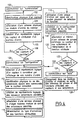
- the first step of the configuration process involves physically identifying each sensor on the network.
- the term sensor refers, in the following, to the torque formed by the control member and the track of the input module to which this organ is connected ordered.
- the switch 80 is set to step 100 on a first position called "numbering".
- the physical identification by the operator of a in step 102 depending on the type of sensor either by the support, directly on it, if it is a push button, either by the depression an identification push button specifically intended on the controller or the input module. This physical identification leads to the emission of a identification message on the network.
- This message is recognized by the Central Configuration Unit 16, which assigns, in step 104, a physical address to the module input, if it is a new input module, to subsequently identify it on the network.
- the physical address is sent to the input module and stored in the memory of it.
- the central unit of configuration 16 creates a logical representative of the sensor which it affects in particular the physical address, the way of the input module and a serial number. This number order is determined incrementally, the first identified sensor bearing the number 1, the following sensors carrying the following successive whole numbers.
- the operator note, for each sensor, the serial number that is awarded.
- the operator deduces himself the number order that the central configuration unit assigns to each sensor, since it knows that the first sensor identified will be assigned the number 1, the second, the number 2, and so on, so the assigned number each sensor corresponds to its actuation rank.
- the central configuration unit provides the operator means for acknowledging the taking into account physical identifications of the sensors by a signal sound.
- step 106 the operator places, at the step 108, the switch 80 on a second position called "configuration".
- This phase of configuration of the actuators consists in associating with each sensor an actuator or a group of actuators and to assign to the sensor and actuators a function to fill. So, according to the mode of operation of this type of network, the solicitation of a controller of a sensor will lead to the actuation of all the actuators associated with this sensor, according to the function that has been assigned to them.
- actuator refers, in the following, to the couple formed by the organ to be controlled and the path of output module to which this organ is connected to order.
- the operator selects a logical representative of a first sensor to be considered, in step 110, by display on the display 82 of the serial number of this sensor. To do this, it causes the scrolling numbers on the display by pressing the keys 84A and 84B.
- the operator physically identifies the actuators to be controlled by this sensor. This operation is performed in step 112 for each actuator by pressing the push button to identify the output module associated with the actuator. This identification is done easily and without moving, when the output modules are placed on the same electric board as the central configuration unit.
- the operator performs an identification physical of these different actuators to control.
- the physical identification of an actuator leads as in the case of the physical identification of a sensor at creation, at step 113, of a representative logic of this actuator by the central configuration unit 16.
- the actuator emits a identification message to the central configuration unit, which then creates a logical representative of the actuator.
- the central configuration unit 16 assigns to the new output module a physical address, allowing its recognition on the network. This physical address is sent to the output module and is stored in the memory of it. This step is omitted if the module output has already been physically addressed. This address physical and the exit route are associated with the representative logic of the actuator and are stored in the memory 56 of the central configuration unit.
- the central configuration unit determines to step 115, from the physical identification message transmitted on the network, the type of actuator identified and deduces the functions attributable to it.
- the microcontroller then controls the ignition of one of the electroluminescent diodes corresponding to the matrix line associated with the type of actuator identified (control of lighting, shutters or heater).
- the central configuration unit checks that all identified actuators are of the same type. If this is not not the case or if the identified actuators are not compatible with the sensor considered, the microcontroller actuates the acoustic signal generator 62. Physical identification is ignored.
- step 116 the operator assigns a function to the logical representatives of the sensor and actuators considered by pressing one of the push buttons 86A to 86E whose associated function is indicated by an ideogram in the row of the matrix designated by the lit diode.
- the depression of a push button 86A at 86E assigns a function to the logical representatives of the selected sensor and actuators identified. then depression of the selection push-button, the diode designating the associated column of this push button lights. Pressing the push button 90, at the step 118, allows the validation of the sensor configuration and associated actuators.
- the configuration CPU 16 affects automatically, in step 120, the same address of group to the logical representative of the sensor considered and to the logical representatives of the identified actuators during the previous step 112. She memorizes in the memory 56 the attribution to the logical representatives of the sensors and actuators this group address as well as the function assigned.
- the depression of the push button 88 allows everything moment the erasure of the memory of the association performed for the sensor currently designated on the display 82.
- Steps 110 to 120 are reproduced thus for each sensor until the sensors to be configured are exhausted.
- the switch 80 is placed, at the step 124, on the "auto" position corresponding to the physical configuration network and triggering the download of data from configuration. These data are saved in the memory 54.
- the central configuration unit 16 proceeds then, in step 126, from the data stored in memory for each logical representative of a sensor or an actuator, downloading group addresses and associated functions in different sensors, and in the different actuators.
- This download is made possible by the prior parameterization of the logical representatives of sensors and actuators which contain the physical addresses of each sensor and each actuator, as well as the address or addresses of group and the functions assigned to them.
- the LED 94 flashes informing the user of the current operation. This step completes the physical configuration of the network.
- each of the sensors and actuators present on the network receives by implementation of this method a group address, allowing the sensors to control actuators with the same address group. Sensors and actuators react according to the downloaded function that was affected.
- the identification output modules are made as and when as the network configuration, sensor after sensor, the functions being assigned immediately after the identification of the output module (s) to associate from the user interface. In these conditions, the identification of the output modules and the assignment of a function is done in a natural way.
- the fourth position of the selector 80 makes it possible to visualize the state of network configuration. So for each sensor selected on the display 82 by its serial number, the function associated with this sensor is designated at the intersection of the row and the column of the matrix whose diodes are on. In addition, the channel diodes output modules with the same group address as the sensor are on.
- the method for the configuration of the network provides the identification previous sensors, as previously described but also that of the actuators.
- the sensors are identified physically successively by the depression of their push buttons.
- the central configuration unit then creates a logical representative of each sensor to which she associates a physical address and a number order.
- the physical address is stored in the memory of the input module of each sensor.
- actuators to configure are physically identified successively by depression of their push buttons.
- the central unit of configuration 16 then creates for each of them a representative logic to which it assigns a serial number and a physical address. The latter is stored in the memory of the output module of each actuator.
- the communication interface of the unit control panel has two displays. A first is intended for displaying sequence numbers attributed to the logical representatives of the sensors. The second is intended for the display of order numbers allocated to the actuators to be associated with the sensor displayed on the first display.
- the communication interface has as before a matrix allowing to assign functions.
- the number order of the logical representative of a sensor is displayed on the first display, while the serial numbers logical representatives of the actuators to be controlled by said sensor are simultaneously displayed on the second display by means of selection to appropriate keys.
- the function to be performed by the actuators thus selected is then defined from the function keys.
- the partial configuration thus defined is memorized by pressing the validation button. This leads to the assignment and memorization of a single group address and function for representatives sensors and actuators.
- This configuration step is thus performed for each sensor in the network.
- data stored by the central configuration unit for each of the logical representatives of the sensors and actuators are then uploaded to the sensors and the actuators.
- each sensor and each actuator comprises a clean push button to ensure its identification.
- each input or output module carries as many pushbuttons as there are tracks, which facilitates configuration and ensures the creation of a logical representative for each new sensor or actuator by simply pressing on its own push-button.
Landscapes
- Engineering & Computer Science (AREA)
- Automation & Control Theory (AREA)
- Computer Networks & Wireless Communication (AREA)
- Signal Processing (AREA)
- Selective Calling Equipment (AREA)
- Data Exchanges In Wide-Area Networks (AREA)
- Programmable Controllers (AREA)
- Small-Scale Networks (AREA)
- Multi Processors (AREA)
Claims (21)
- Verfahren zum Konfigurieren eines Kommunikationsnetzes, das Funktionsmodule umfasst, die aus Signaleingabegliedern (12) und Betätigungsgliedern (14) gebildet sind, die direkt miteinander über einen Kommunikationsbus (10) kommunizieren, wobei die Signaleingabeglieder (12) und die Betätigungsglieder (14) nach der Konfiguration jeweils Konfigurationsparameter aufweisen, die es jedem Signaleingabeglied erlauben, gewisse Betätigungsglieder anzusteuern, welche Konfigurationsparameter von einer zentralen Konfigurationseinheit (16) zugeordnet werden, dadurch gekennzeichnet, dass es zum Konfigurieren eines neuen Funktionsmoduls, der in das Netz eingefügt wird, die folgenden Schritte umfasst:A) Man identifiziert physikalisch den neuen Funktionsmodul am Netz über das Drücken einer Drucktaste, die der besagte Funktionsmodul trägt,B) der neue Funktionsmodul gibt nach seiner physikalischen Identifikation durch das Drücken der besagten Drucktaste eine Identifikationsmitteilung an die zentrale Konfigurationseinheit aus,C) auf den Empfang dieser Identifikationsmitteilung erzeugt die zentrale Konfigurationseinheit (16) einen logischen Repräsentanten des neuen Funktionsmoduls,D) ausgehend von der zentralen Konfigurationseinheit (16) ordnet man Konfigurationsparameter dem logischen Repräsentanten des neuen Funktionsmoduls zu, wobei die Konfigurationsparameter jedes Funktionsmoduls wenigstens eine Gruppenadresse umfassen, die es jedem Signaleingabeglied erlaubt, Betätigungsglieder anzusteuern, die dieselbe Gruppenadresse wie das Signaleingabeglied haben,E) die zentrale Konfigurationseinheit lädt die Konfigurationsparameter, die dem logischen Repräsentanten des neuen Funktionsmoduls zugeordnet sind, in den neuen Funktionsmodul, und
dass die Zuordnung im Schritt D) einer Gruppenadresse zum logischen Repräsentanten des Signaleingabegliedes oder des Betätigungsgliedes, das den neuen Funktionsmodul bildet, die folgenden Schritte umfasst:(i) Man wählt den logischen Repräsentanten eines betreffenden Signaleingabegliedes,(ii) man wählt die logischen Repräsentanten der Betätigungsglieder, die durch das besagte betreffende Signaleingabeglied anzusteuern sind, und(iii) die zentrale Konfigurationseinheit ordnet dem logischen Repräsentanten des betreffenden Signaleingabegliedes und den logischen Repräsentanten der besagten Betätigungsglieder die selbe Gruppenadresse zu. - Verfahren nach Anspruch 1, dadurch gekennzeichnet, dass nach dem Empfang der besagten Identifikationsmitteilung die zentrale Konfigurationseinheit (16) dem neuen Funktionsmodul eine physikalische Adresse zuordnet und diese Adresse in den neuen Funktionsmodul lädt, die eine spätere Kommunikation zwischen dem neuen Funktionsmodul und der zentralen Konfigurationseinheit erlaubt.
- Verfahren nach Anspruch 1 oder 2, dadurch gekennzeichnet, dass man nach der Wahl des Signaleingabegliedes und der Betätigungsglieder, die durch das besagte Signaleingabeglied anzusteuern sind in den Schritte (i) und (ii) eine von den Betätigungsgliedern unter der Steuerung des besagten Signaleingabegliedes auszuführende Funktion wählt, welche Funktion dann in die besagten Signaleingabeglieder und Betätigungsglieder durch die zentral Konfigurationseinheit geladen wird.
- Verfahren nach Anspruch 3, dadurch gekennzeichnet, dass es zum Konfigurieren mehrerer neuer Funktionsmodule die folgenden Schritte umfasst:a) Man führt für jedes neue Signaleingabeglied die Schritte A, B und C der physikalischen Identifikation, der Ausgabe einer Identifikationsmitteilung und der Erzeugung eines logischen Repräsentanten des neuen Signaleingabegliedes aus,b) man führt für jedes Signaleingabeglied die folgenden Schritte b0 bis b3 aus:b0) man wählt einen logischen Repräsentanten des betreffenden Eingabegliedes,b1) man führt für die Betätigungsglieder, die von dem besagten betreffenden Signaleingabeglied anzusteuern sind, die Schritte A, B und C der physikalischen Identifikation, der Ausgabe einer Identifikationsmitteilung und dann, wenn das Betätigungsglied physikalisch zum ersten Mal identifiziert wird, der Erzeugung eines logischen Repräsentanten dieses Gliedes aus, welche Schritte zur Auswahl logischer Repräsentanten der Betätigungsglieder führen, die durch das betreffende Signaleingabeglied anzusteuern sind,b2) die zentrale Konfigurationseinheit ordnet die selbe Gruppenadresse dem logischen Repräsentanten des betreffenden Signaleingabegliedes und den logischen Repräsentanten der gewählten Betätigungsglieder zu, die von dem betreffenden Signaleingabeglied anzusteuern sind,b3) man wählt von der zentralen Konfigurationseinheit eine Funktion, die von den besagten gewählten Betätigungsgliedern unter der Steuerung des besagten Signaleingabegliedes auszuführen ist, welche Funktion den logischen Repräsentanten des Signaleingabegliedes und der Betätigungsglieder zugeordnet wird, undc) die zentrale Konfigurationseinheit lädt die Gruppenadressen und die Funktionen, die ihren logischen Repräsentanten zugeordnet sind, in die Signaleingabeglieder und die Betätigungsglieder.
- Verfahren nach Anspruch 3, dadurch gekennzeichnet, dass es zur Konfiguration von mehreren neuen Funktionsmodulen die folgenden Schritte umfasst:a) man führt für jedes neue Signaleingabeglied und für jedes neue Betätigungsglied die Schritte A, B und C der physikalischen Identifikation, der Ausgabe einer Identifikationsmitteilung und der Erzeugung eines logischen Repräsentanten des Signaleingabegliedes oder des neuen Betätigungsgliedes aus,b) man führt für jedes Signaleingabeglied die folgenden Schritte b0 bis b3 aus:b0) man wählt den logischen Repräsentanten des betreffenden Signaleingabegliedes,b1) man wählt die logischen Repräsentanten der Betätigungsglieder, die durch das betreffende besagte Signaleingabeglied anzusteuern sind,b2) die zentrale Konfigurationseinheit ordnet die selbe Gruppenadresse dem logischen Repräsentanten des betreffenden Signaleingabegliedes und den logischen Repräsentanten der gewählten Betätigungsglieder zu, die durch das besagte betreffende Signaleingabeglied anzusteuern sind,b3) man wählt von der zentralen Konfigurationseinheit eine Funktion, die durch die gewählten besagten Betätigungsglieder unter der Steuerung des besagten Signaleingabegliedes auszuführen ist, welche Funktion den logischen Repräsentanten des Signaleingabegliedes und der Betätigungsglieder zugeordnet wird, undc) die zentrale Konfigurationseinheit lädt die Gruppenadressen und die Funktionen, die ihren logischen Repräsentanten zugeordnet sind, in die Signaleingabeglieder und die Betätigungsglieder.
- Verfahren nach Anspruch 4 oder 5, dadurch gekennzeichnet, dass es bei dem Schritt der Wahl und der Zuordnung einer auszuführenden Funktion zu den logischen Repräsentanten des Signaleingabegliedes und der gewählten Betätigungsglieder die folgenden Schritte umfasst:i) Man schreibt dem betreffenden Signaleingabeglied eine einzelne Funktion zum Steuerung der gewählten Betätigungsglieder zu,ii) man ordnet den logischen Repräsentanten aller gewählten Betätigungsglieder die einzelne Funktion zu, die dem betreffenden Signaleingabeglied zugeschrieben wurde.
- Verfahren nach einem der Ansprüche 4 bis 6, dadurch gekennzeichnet, dass man eine Ordnungszahl jedem logischen Repräsentanten eines Signaleingabegliedes während der Erzeugung des logischen Repräsentanten zuschreibt, und dass die für jedes Signaleingabeglied ausgeführten Schritte in Abhängigkeit von der Ordnungszahl ausgeführt werden, wobei das besagte Signaleingabeglied durch die besagte Ordnungszahl bezeichnet wird.
- Vorrichtung zum Konfigurieren eines Kommunikationsnetzes, welches Netz Funktionsmodute umfasst, die aus Signaleingabegliedern (12) und Betätigungsgliedern (14) gebildet sind, die direkt miteinander über einen Kommunikationsbus (10) kommunizieren, wobei die Signaleingabeglieder (12) und die Betätigungsglieder (14) nach der Konfiguration jeweils Konfigurationsparameter aufweisen, die es jedem Signaleingabeglied erlauben, gewisse Betätigungsglieder anzusteuern, welche Vorrichtung eine zentrale Konfigurationseinheit (16) zum Zuordnen der Konfigurationsparameter umfasst, dadurch gekennzeichnet, dass sie zum Konfigurieren eines neuen Funktionsmoduls, der in das Netz eingeführt wird,A) Einrichtungen zum physikalischen Identifizieren des neuen Funktionsmoduls am Netz, welche Einrichtungen eine Identifikationsdrucktaste umfassen, die an jedem Funktionsmodul vorgesehen ist,B) Einrichtungen, die von jedem neuen Funktionsmodul anschließend an seine physikalische Identifikation durch Drücken der besagte Drucktaste eine Identifikationsmitteilung an die zentrale Konfigurationseinrichtung ausgeben,C) Einrichtungen, die auf den Empfang der besagten Identifikationsmitteilung von der zentralen Konfigurationseinheit einen logischen Repräsentanten des neuen Funktionsmoduls erzeugen,D) Einrichtungen, die von der zentralen Konfigurationseinheit Konfigurationsparameter dem logischen Repräsentanten des neuen Funktionsmoduls zuordnen, wobei die Konfigurationsparameter jedes Funktionsmoduls wenigstens eine Gruppenadresse umfassen, die es jedem Signaleingabeglied erlaubt, Betätigungsglieder anzusteuern, die die gleiche Gruppenadresse wie das Signaleingabeglied haben,E) Einrichtungen, die von der zentralen Konfigurationseinheit in den neuen Funktionsmodul die Konfigurationsparameter laden, die dem logischen Repräsentanten des neuen Funktionsmoduls zugeordnet wurden, umfasst,
und dass sie(i) Einrichtungen zum Wählen des logischen Repräsentanten eines betreffenden Signaleingabegliedes, die in die zentrale Konfigurationseinheit integriert sind,(ii) Einrichtungen zum Wählen der logischen Repräsentanten der Betätigungsglieder, die von dem besagten betreffenden Signaleingabeglied anzusteuern sind.(iii) Einrichtungen zum Zuordnen derselben Gruppenadresse zu dem logischen Repräsentanten des betreffenden Signaleingabegliedes und zu den logischen Repräsentanten der besagten Betätigungsglieder, die in die zentrale Konfigurationseinheit integriert sind, aufweist. - Vorrichtung nach Anspruch 8, dadurch gekennzeichnet, dass die zentrale Konfigurationseinheit (16) eine Mikrosteuerung (50) umfasst, die einerseits mit einer Kopplungseinheit (52) zum Übertragen von Informationen zwischen der Mikrosteuerung (50) und den Signaleingabegliedern (12) und den Betätigungsgliedern (14), die am Bus vorhanden sind, und andererseits mit einer Konfigurationstafel (64) verbunden ist, die eine Anwender-Schnittstelle trägt.
- Vorrichtung nach Anspruch 8 oder 9, dadurch gekennzeichnet, dass die zentrale Konfigurationseinheit Einrichtungen zum Wählen einer von den besagten Betätigungsgliedern unter der Steuerung des besagten Signaleingabegliedes auszuführenden Funktion und Einrichtungen zum Laden der besagten Funktion in die besagten Signaleingabeglieder und in die besagten Betätigungsglieder umfasst.
- Vorrichtung nach Anspruch 10, dadurch gekennzeichnet, dass sie zum Konfigurieren mehrerer neuer Funktionsmodulea) Einrichtungen, die für jedes neue Signaleingabeglied die physikalische Identifikation, die Ausgabe einer Identifikationsmitteilung und die Erzeugung eines logischen Repräsentanten des neuen Signaleingabegliedes bewirken,b) Einrichtungen, die für jedes Signaleingabegliedb0) eine Wahl des logischen Repräsentanten des betreffenden Signaleingabegliedes bewirken,b1) für die Betätigungsglieder, die von dem besagten betreffenden Signaleingabeglied anzusteuern sind, die physikalische Identifikation, die Ausgabe einer Identifikationsmitteilung und dann, wenn das Betätigungsglied physikalisch zum ersten Mal identifiziert wird, die Erzeugung eines logischen Repräsentanten dieses Gliedes bewirken, wobei das zu einer Auswahl der logischen Repräsentanten der Betätigungsglieder führt, die von dem betreffenden Signaleingabeglied anzusteuern sind,b2) eine Zuordnung von der zentralen Konfigurationseinheit derselben Gruppenadresse zum logischen Repräsentanten des betreffenden Signaleingabegliedes und zu den logischen Repräsentanten der gewählten Betätigungsglieder bewirken, die von dem betreffenden Signaleingabeglied anzusteuern sind,b3) eine Wahl von der zentralen Konfigurationseinheit einer Funktion bewirken, die von den gewählten Betätigungsgliedern unter der Steuerung des besagten Signaleingabegliedes auszuführen ist, welche Funktion den logischen Repräsentanten des Signaleingabegliedes und der Betätigungsglieder zugeordnet wird, undc) Einrichtungen, die von der zentralen Konfigurationseinheit die Gruppenadressen und die ihren logischen Repräsentanten zugeordneten Funktionen in die Signaleingabeglieder und die Betätigungsglieder laden, umfasst.
- Vorrichtung nach Anspruch 10, dadurch gekennzeichnet, dass sie zum Konfigurieren von mehreren neuen Funktionsmodulena) Einrichtungen, die für jedes neue Signaleingabeglied und für jedes neue Betätigungsglied die physikalische Identifikation, die Ausgabe einer Identifikationsmitteilung und die Erzeugung eines logischen Repräsentanten des neuen Signaleingabegliedes und des neuen Betätigungsgliedes ausführen,b) Einrichtungen, die für jedes Signaleingabegliedb0) eine Wahl des logischen Repräsentanten des betreffenden Signaleingabegliedes bewirken,b1) eine Wahl der logischen Repräsentanten der Betätigungsglieder bewirken, die von dem besagten betreffenden Signaleingabeglied anzusteuern sind,b2) eine Zuordnung von der zentralen Konfigurationseinheit derselben Gruppenadresse zu dem logischen Repräsentanten des betreffenden Signaleingabegliedes und zu den logischen Repräsentanten der gewählten Betätigungsglieder, bewirken die von dem betreffenden Signaleingabeglied anzusteuern sind,b3) eine Wahl von der zentralen Konfigurationseinheit einer Funktion bewirken, die von den gewählten besagten Betätigungsgliedern unter der Steuerung des besagten Signaleingabegliedes auszuführen ist, welche Funktion den logischen Repräsentanten der Signaleingabeglieder und der Betätigungsglieder zugeordnet wird, undc) Einrichtungen, die von der zentralen Konfigurationseinheit in die Signaleingabeglieder und in die Betätigungsglieder die Gruppenadressen und die Funktionen laden, die ihrem logischen Repräsentanten zugeordnet sind, umfasst.
- Vorrichtung nach Anspruch 11 oder 12, dadurch gekennzeichnet, dass die zentrale Konfigurationseinheiti) Einrichtungen, die dem betreffenden Signaleingabeglied eine einzelne Funktion zum Steuern der gewählten Betätigungsglieder zuschreiben,ii) Einrichtungen, die den logischen Repräsentanten aller gewählten Betätigungsglieder die gleiche einzelne Funktion zuordnen, die dem betreffenden Signaleingabeglied zugeschrieben ist.
- Vorrichtung nach Anspruch 13, dadurch gekennzeichnet, dass die Einrichtungen, die dem Signaleingabeglied eine einzelne Funktion zum Steuern der gewählten Betätigungsfelder zuschreiben, eine Konfigurationstafel (64) umfassen, die mit Drucktasten (86A, 86B, 86C, 86D, 86E) zum Wählen einer bestimmten Funktion ausgerüstet ist, wobei jede Drucktaste wenigstens einer Funktion zugeordnet ist.
- Vorrichtung nach Anspruch 14, dadurch gekennzeichnet, dass sie Einrichtungen zum Identifizieren der Art des gewählten Betätigungsgliedes und Einrichtungen zum Zuordnen wählbarer Funktionen zu den Drucktasten (86A, 86B, 86C, 86D, 86E) umfasst, die mit der Art des gewählten Betätigungsgliedes kompatibei sind.
- Vorrichtung nach einem der Ansprüche 8 bis 15, dadurch gekennzeichnet, dass die zentrale Konfigurationseinheit Einrichtungen umfasst, die eine physikalische Adresse dem identifizierten neuen Funktionsmodul zuordnen und in diesen Modul laden, nachdem die besagte Identifikationsmitteilung empfangen worden ist.
- Vorrichtung nach einem Ansprüche 8 bis 16, dadurch gekennzeichnet, dass die zentrale Konfigurationseinheit (16) Einrichtungen umfasst, die die Signaleingabeglieder während Ihrer physikalischen Identifikation nummerieren, und dass sie Einrichtungen umfasst, die zugeordnete Nummern wählen, um ein zu betrachtendes Signaleingabeglied zu wählen.
- Vorrichtung nach Anspruch 17, dadurch gekennzeichnet, dass die zentrale Konfigurationseinheit (16) Einrichtungen (82) zum Anzeigen der den Signaleingabegliedern zugeordneten Nummern umfasst.
- Vorrichtung nach einem der Ansprüche 8 bis 18, dadurch gekennzeichnet, dass die zentrale Konfigurationseinheit (16) Speichereinrichtungen (56) zum Speichern der zugeordneten Konfigurationsparameter vor ihrem Laden in die Signaleingabeglieder oder in die Betätigungsglieder umfasst.
- Kommunikationsnetz mit Signaleingabegliedern (12) und Betätigungsgliedern (14), die direkt miteinander über einen Kommunikationsbus (10) kommunizieren, wobei die Signaleingabeglieder und die Betätigungsglieder jeweils nach ihrer Konfiguration Konfigurationsparameter aufweisen, die es jedem Signaleingabeglied erlauben, die Betätigungsglieder anzusteuern, dadurch gekennzeichnet, dass es eine Vorrichtung zum Konfigurieren nach einem Ansprüche 8 bis 19 umfasst.
- Netz nach Anspruch 20, dadurch gekennzeichnet, dass jedes Betätigungsglied (14) einen Ausgangsmodul (30, 34, 38) umfasst, der mit einem anzusteuernden Eiement (32, 36, 40) verbunden ist, welche Ausgangsmodul Einrichtungen zum Ansteuern des anzusteuernden Elementes und Einrichtungen (B) umfasst, die eine physikalische Identifikation des Betätigungsgliedes am Netz erlauben, und dass die Ausgangsmodule und die besagte zentrale Konfigurationseinheit (16) in unmittelbarer Nähe zueinander, insbesondere auf derselben elektrischen Schalttafel (41), vorgesehen sind, so dass sie gleichzeitig zugänglich sind.
Applications Claiming Priority (2)
| Application Number | Priority Date | Filing Date | Title |
|---|---|---|---|
| FR9608355A FR2750819B1 (fr) | 1996-07-04 | 1996-07-04 | Procede et dispositif de configuration d'un reseau de communication |
| FR9608355 | 1996-07-04 |
Publications (2)
| Publication Number | Publication Date |
|---|---|
| EP0817423A1 EP0817423A1 (de) | 1998-01-07 |
| EP0817423B1 true EP0817423B1 (de) | 2005-09-28 |
Family
ID=9493722
Family Applications (1)
| Application Number | Title | Priority Date | Filing Date |
|---|---|---|---|
| EP97401563A Expired - Lifetime EP0817423B1 (de) | 1996-07-04 | 1997-07-02 | Verfahren und Vorrichtung zum Konfigurieren eines Kommunikationsnetzes |
Country Status (4)
| Country | Link |
|---|---|
| EP (1) | EP0817423B1 (de) |
| AT (1) | ATE305687T1 (de) |
| DE (1) | DE69734261T2 (de) |
| FR (1) | FR2750819B1 (de) |
Families Citing this family (8)
| Publication number | Priority date | Publication date | Assignee | Title |
|---|---|---|---|---|
| US6359270B1 (en) | 1998-09-04 | 2002-03-19 | Ncr Corporation | Communications module mounting for domestic appliance |
| US6559882B1 (en) | 1999-09-02 | 2003-05-06 | Ncr Corporation | Domestic appliance |
| ATE291322T1 (de) | 1999-08-23 | 2005-04-15 | Pilz Gmbh & Co | Verfahren zum konfigurieren eines sicheren busteilnehmers und sicheres steuerungssystem mit einem solchen |
| GB0313473D0 (en) * | 2003-06-11 | 2003-07-16 | Koninkl Philips Electronics Nv | Configuring a radio network for selective broadcast |
| US20060020690A1 (en) * | 2004-06-17 | 2006-01-26 | Richards Martin J | Network topology and method of operation for a playback system in a digital cinema network |
| DE102006020122A1 (de) * | 2006-05-02 | 2007-11-08 | Siemens Ag | Verfahren zum vollständigen Erfassen der Daten betreffend Verknüpfungen von Sensoren und Aktoren in einem drahtlos kommunizierenden Installationssystem |
| DE102009051386A1 (de) * | 2009-10-30 | 2011-05-12 | Siemens Aktiengesellschaft | Verfahren zum Zuordnen eines physikalischen Kanals eines Sensors, der an einen Bus eines Bus-Systems angeschlossen ist, zu einem Kanal eines in einem Inbetriebnahmeprogramm virtuell dargestellten Sensors sowie Sensor und Inbetriebnahmeprogramm |
| DE102011075608A1 (de) * | 2011-05-10 | 2012-11-15 | Siemens Aktiengesellschaft | Verfahren zum Zuordnen eines physikalischen Kanals eines Sensors, der an einen Bus eines Bus-Systems angeschlossen ist, zu einem Kanal eines in einem Inbetriebnahmeprogramm virtuell dargestellten Sensors sowie Sensor und Inbetriebnahmeprogramm |
Family Cites Families (5)
| Publication number | Priority date | Publication date | Assignee | Title |
|---|---|---|---|---|
| US5107256A (en) * | 1987-11-02 | 1992-04-21 | Matsushita Electric Industrial Co., Ltd. | Method and apparatus for controlling terminals on communication network |
| WO1990015394A1 (en) * | 1989-06-02 | 1990-12-13 | Aisi Research Corporation | Appliance interface for exchanging data |
| FR2664761A1 (fr) * | 1990-07-13 | 1992-01-17 | Moulinex Sa | Dispositif de commande de plusieurs emetteurs-recepteurs electriques montes dans un reseau de distribution d'energie electrique. |
| FR2670590B1 (fr) * | 1990-12-13 | 1993-11-26 | Gilbert Jerome | Procede de mise en correspondance, d'un appareil de commande avec un appareil d'action, et d'attribution d'adresses dans un reseau domotique. |
| JPH06164592A (ja) * | 1992-11-16 | 1994-06-10 | Hitachi Ltd | Lanにおける端末構成情報自動反映更新方式 |
-
1996
- 1996-07-04 FR FR9608355A patent/FR2750819B1/fr not_active Expired - Fee Related
-
1997
- 1997-07-02 DE DE69734261T patent/DE69734261T2/de not_active Expired - Lifetime
- 1997-07-02 AT AT97401563T patent/ATE305687T1/de not_active IP Right Cessation
- 1997-07-02 EP EP97401563A patent/EP0817423B1/de not_active Expired - Lifetime
Also Published As
| Publication number | Publication date |
|---|---|
| EP0817423A1 (de) | 1998-01-07 |
| ATE305687T1 (de) | 2005-10-15 |
| FR2750819B1 (fr) | 2000-08-25 |
| DE69734261D1 (de) | 2006-02-09 |
| FR2750819A1 (fr) | 1998-01-09 |
| DE69734261T2 (de) | 2006-07-06 |
Similar Documents
| Publication | Publication Date | Title |
|---|---|---|
| EP0574636B1 (de) | Verfahren zur Adressierung einer Betriebseinrichtung und zur Verbindung von zwei Betriebseinrichtungen; Betriebseinrichtung und Anlage dafür | |
| US6967565B2 (en) | Building automation system | |
| US8219219B2 (en) | Method and system of programming at least one appliance to change state upon the occurrence of a trigger event | |
| EP0817423B1 (de) | Verfahren und Vorrichtung zum Konfigurieren eines Kommunikationsnetzes | |
| ES2317876T3 (es) | Dispositivos adaptable al usuario y mejorables y metodos correspondientes. | |
| US8955979B2 (en) | Display projector for textual signage | |
| NO175958B (no) | Styringssystem for flere apparater | |
| CA2647983A1 (en) | Reconfigurable programmable thermostat | |
| WO2001054406A1 (en) | Method of configuring a consumer electronics apparatus | |
| FR2628335A1 (fr) | Installation pour assurer la regie du son, de la lumiere et/ou d'autres effets physiques d'un spectacle | |
| CA2262187A1 (en) | Control station for control system with automatic detection and configuration of control elements | |
| JP4352549B2 (ja) | 受信装置 | |
| JP2003087881A (ja) | 学習リモコン、リモコン機能学習システムおよびリモコン機能学習方法 | |
| EP3216096B1 (de) | Elektrische installation bestehend aus einer elektrischen schalttafel und mehreren elektrischen anschlusspunkten | |
| FR2721767A3 (fr) | Système de commande pour la commande de plusieurs consommateurs. | |
| FR2691281A1 (fr) | Procédé et dispositif d'enregistrement et de reproduction d'états complexes dans un réseau d'équipements d'un local, et installation s'y rapportant. | |
| EP1480497A2 (de) | System zur Fernsteuerung von Leuchtvorrichtungen | |
| EP0495322A1 (de) | Elektrisches Kontroll- und Steuerungssystem einer Funktionseinheit, insbesondere eines Hauses eines Gebäudes, eines Schiffes oder dergleichen | |
| WO2001019417A1 (fr) | Dispositif dynamique de diffusion de parfums et procede de pilotage de ce dispositif | |
| LU505516B1 (fr) | Système de ventilation mécanique contrôlée pour la ventilation d'au moins un logement | |
| WO2008084356A1 (en) | Network communication system | |
| FR2624627A1 (fr) | Pilote programmable de gestion d'energie electrique | |
| CN100525061C (zh) | 自动遮光帘控制系统 | |
| Brewer | Home automation made easy: do it yourself know how using UPB, Insteon, X10 and Z-Wave | |
| KR20040069530A (ko) | 전자 제품의 원격 제어 방법 및 시스템 |
Legal Events
| Date | Code | Title | Description |
|---|---|---|---|
| PUAI | Public reference made under article 153(3) epc to a published international application that has entered the european phase |
Free format text: ORIGINAL CODE: 0009012 |
|
| AK | Designated contracting states |
Kind code of ref document: A1 Designated state(s): AT BE CH DE DK ES FI FR GB GR IE IT LI LU MC NL PT SE |
|
| AX | Request for extension of the european patent |
Free format text: AL;LT;LV;RO;SI |
|
| 17P | Request for examination filed |
Effective date: 19980620 |
|
| AKX | Designation fees paid |
Free format text: AT BE CH DE DK ES FI FR GB GR IE IT LI LU MC NL PT SE |
|
| RBV | Designated contracting states (corrected) |
Designated state(s): AT BE CH DE DK ES FI FR GB GR IE IT LI LU MC NL PT SE |
|
| 17Q | First examination report despatched |
Effective date: 20040202 |
|
| GRAP | Despatch of communication of intention to grant a patent |
Free format text: ORIGINAL CODE: EPIDOSNIGR1 |
|
| GRAS | Grant fee paid |
Free format text: ORIGINAL CODE: EPIDOSNIGR3 |
|
| GRAA | (expected) grant |
Free format text: ORIGINAL CODE: 0009210 |
|
| AK | Designated contracting states |
Kind code of ref document: B1 Designated state(s): AT BE CH DE DK ES FI FR GB GR IE IT LI LU MC NL PT SE |
|
| PG25 | Lapsed in a contracting state [announced via postgrant information from national office to epo] |
Ref country code: NL Free format text: LAPSE BECAUSE OF FAILURE TO SUBMIT A TRANSLATION OF THE DESCRIPTION OR TO PAY THE FEE WITHIN THE PRESCRIBED TIME-LIMIT Effective date: 20050928 Ref country code: IT Free format text: LAPSE BECAUSE OF FAILURE TO SUBMIT A TRANSLATION OF THE DESCRIPTION OR TO PAY THE FEE WITHIN THE PRESCRIBED TIME-LIMIT;WARNING: LAPSES OF ITALIAN PATENTS WITH EFFECTIVE DATE BEFORE 2007 MAY HAVE OCCURRED AT ANY TIME BEFORE 2007. THE CORRECT EFFECTIVE DATE MAY BE DIFFERENT FROM THE ONE RECORDED. Effective date: 20050928 Ref country code: IE Free format text: LAPSE BECAUSE OF FAILURE TO SUBMIT A TRANSLATION OF THE DESCRIPTION OR TO PAY THE FEE WITHIN THE PRESCRIBED TIME-LIMIT Effective date: 20050928 Ref country code: GB Free format text: LAPSE BECAUSE OF FAILURE TO SUBMIT A TRANSLATION OF THE DESCRIPTION OR TO PAY THE FEE WITHIN THE PRESCRIBED TIME-LIMIT Effective date: 20050928 Ref country code: FI Free format text: LAPSE BECAUSE OF FAILURE TO SUBMIT A TRANSLATION OF THE DESCRIPTION OR TO PAY THE FEE WITHIN THE PRESCRIBED TIME-LIMIT Effective date: 20050928 Ref country code: AT Free format text: LAPSE BECAUSE OF FAILURE TO SUBMIT A TRANSLATION OF THE DESCRIPTION OR TO PAY THE FEE WITHIN THE PRESCRIBED TIME-LIMIT Effective date: 20050928 |
|
| REG | Reference to a national code |
Ref country code: GB Ref legal event code: FG4D Free format text: NOT ENGLISH |
|
| REG | Reference to a national code |
Ref country code: CH Ref legal event code: EP |
|
| REG | Reference to a national code |
Ref country code: IE Ref legal event code: FG4D Free format text: LANGUAGE OF EP DOCUMENT: FRENCH |
|
| RAP2 | Party data changed (patent owner data changed or rights of a patent transferred) |
Owner name: HAGER CONTROLS |
|
| PG25 | Lapsed in a contracting state [announced via postgrant information from national office to epo] |
Ref country code: SE Free format text: LAPSE BECAUSE OF FAILURE TO SUBMIT A TRANSLATION OF THE DESCRIPTION OR TO PAY THE FEE WITHIN THE PRESCRIBED TIME-LIMIT Effective date: 20051228 Ref country code: GR Free format text: LAPSE BECAUSE OF FAILURE TO SUBMIT A TRANSLATION OF THE DESCRIPTION OR TO PAY THE FEE WITHIN THE PRESCRIBED TIME-LIMIT Effective date: 20051228 Ref country code: DK Free format text: LAPSE BECAUSE OF FAILURE TO SUBMIT A TRANSLATION OF THE DESCRIPTION OR TO PAY THE FEE WITHIN THE PRESCRIBED TIME-LIMIT Effective date: 20051228 |
|
| NLT2 | Nl: modifications (of names), taken from the european patent patent bulletin |
Owner name: HAGER CONTROLS Effective date: 20051116 |
|
| PG25 | Lapsed in a contracting state [announced via postgrant information from national office to epo] |
Ref country code: ES Free format text: LAPSE BECAUSE OF FAILURE TO SUBMIT A TRANSLATION OF THE DESCRIPTION OR TO PAY THE FEE WITHIN THE PRESCRIBED TIME-LIMIT Effective date: 20060108 |
|
| REF | Corresponds to: |
Ref document number: 69734261 Country of ref document: DE Date of ref document: 20060209 Kind code of ref document: P |
|
| PG25 | Lapsed in a contracting state [announced via postgrant information from national office to epo] |
Ref country code: PT Free format text: LAPSE BECAUSE OF FAILURE TO SUBMIT A TRANSLATION OF THE DESCRIPTION OR TO PAY THE FEE WITHIN THE PRESCRIBED TIME-LIMIT Effective date: 20060228 |
|
| NLV1 | Nl: lapsed or annulled due to failure to fulfill the requirements of art. 29p and 29m of the patents act | ||
| GBV | Gb: ep patent (uk) treated as always having been void in accordance with gb section 77(7)/1977 [no translation filed] |
Effective date: 20050928 |
|
| REG | Reference to a national code |
Ref country code: IE Ref legal event code: FD4D |
|
| PG25 | Lapsed in a contracting state [announced via postgrant information from national office to epo] |
Ref country code: MC Free format text: LAPSE BECAUSE OF NON-PAYMENT OF DUE FEES Effective date: 20060731 Ref country code: BE Free format text: LAPSE BECAUSE OF NON-PAYMENT OF DUE FEES Effective date: 20060731 |
|
| PLBE | No opposition filed within time limit |
Free format text: ORIGINAL CODE: 0009261 |
|
| STAA | Information on the status of an ep patent application or granted ep patent |
Free format text: STATUS: NO OPPOSITION FILED WITHIN TIME LIMIT |
|
| 26N | No opposition filed |
Effective date: 20060629 |
|
| BERE | Be: lapsed |
Owner name: HAGER ELECTRO S.A. Effective date: 20060731 |
|
| PG25 | Lapsed in a contracting state [announced via postgrant information from national office to epo] |
Ref country code: LU Free format text: LAPSE BECAUSE OF NON-PAYMENT OF DUE FEES Effective date: 20060702 |
|
| REG | Reference to a national code |
Ref country code: DE Ref legal event code: R082 Ref document number: 69734261 Country of ref document: DE Representative=s name: DR. RALF KOTITSCHKE, DE Ref country code: DE Ref legal event code: R082 Ref document number: 69734261 Country of ref document: DE Representative=s name: KOTITSCHKE & HEURUNG PARTNERSCHAFT MBB, DE Ref country code: DE Ref legal event code: R082 Ref document number: 69734261 Country of ref document: DE Representative=s name: KOTITSCHKE & HEURUNG PARTNERSCHAFT MBB PATENT-, DE |
|
| REG | Reference to a national code |
Ref country code: FR Ref legal event code: PLFP Year of fee payment: 20 |
|
| PGFP | Annual fee paid to national office [announced via postgrant information from national office to epo] |
Ref country code: CH Payment date: 20160718 Year of fee payment: 20 Ref country code: DE Payment date: 20160719 Year of fee payment: 20 |
|
| PGFP | Annual fee paid to national office [announced via postgrant information from national office to epo] |
Ref country code: FR Payment date: 20160715 Year of fee payment: 20 |
|
| REG | Reference to a national code |
Ref country code: DE Ref legal event code: R071 Ref document number: 69734261 Country of ref document: DE |
|
| REG | Reference to a national code |
Ref country code: CH Ref legal event code: PL |