EP0817437A2 - Nachrichtenübertragung in Rechnernetze - Google Patents
Nachrichtenübertragung in Rechnernetze Download PDFInfo
- Publication number
- EP0817437A2 EP0817437A2 EP97304722A EP97304722A EP0817437A2 EP 0817437 A2 EP0817437 A2 EP 0817437A2 EP 97304722 A EP97304722 A EP 97304722A EP 97304722 A EP97304722 A EP 97304722A EP 0817437 A2 EP0817437 A2 EP 0817437A2
- Authority
- EP
- European Patent Office
- Prior art keywords
- message
- switching
- switching nodes
- buffer
- nodes
- Prior art date
- Legal status (The legal status is an assumption and is not a legal conclusion. Google has not performed a legal analysis and makes no representation as to the accuracy of the status listed.)
- Withdrawn
Links
Images

Classifications
-
- H—ELECTRICITY
- H04—ELECTRIC COMMUNICATION TECHNIQUE
- H04L—TRANSMISSION OF DIGITAL INFORMATION, e.g. TELEGRAPHIC COMMUNICATION
- H04L12/00—Data switching networks
- H04L12/28—Data switching networks characterised by path configuration, e.g. LAN [Local Area Networks] or WAN [Wide Area Networks]
- H04L12/42—Loop networks
-
- H—ELECTRICITY
- H04—ELECTRIC COMMUNICATION TECHNIQUE
- H04L—TRANSMISSION OF DIGITAL INFORMATION, e.g. TELEGRAPHIC COMMUNICATION
- H04L12/00—Data switching networks
- H04L12/54—Store-and-forward switching systems
- H04L12/56—Packet switching systems
Definitions
- This invention relates to message transfer in computer networks.
- a number of types of multiprocessor computer systems have been developed which integrate a number of processors to increase the system's processing power beyond that which can be provided by a single processor.
- a plurality of processing nodes are interconnected by communication links which may comprise any suitable mechanism for transferring digital information, including, for example, wires, optical fibers, and the like.
- interconnection arrangements have been developed for interconnecting processors in a multiprocessor computer system designed according to the distributed memory model, organized in a number of topologies.
- a simple bus to which all processing nodes are connected may suffice.
- contention for the bus increases, which can slow down information transfer and the processing capability of the respective systems.
- interconnection topologies that have been proposed, studied and/or implemented, other than the aforementioned bus arrangement, have been developed for systems including a large number of processing nodes, in particular, systems numbering in the hundreds or thousands of processing nodes.
- many systems that are desired commercially are much smaller, having, for example, as few as four or five processing nodes, up to as many as fifteen to twenty.
- interconnection topologies that have been developed for large systems are often not economical.
- Another problem with such interconnection topologies is that they are typically based on the assumption that the systems with which they are to be used includes a number of processing nodes corresponding to a power of two, and will be most economical for those numbers of processing nodes. If, for example, such a system is required to have a number of processing nodes corresponding to a power of two, it may be necessary to increase the interconnection subsystem considerably even if it is desired to increase the number of processing nodes by only one.
- interconnection subsystems for interconnecting small numbers of nodes, each having a selected "degree,” or “radix,” (that is, or number of connections to communication links) in a multiprocessor computer system, it may be that all of the nodes are of degree "three,” so that each processing node can connect to as many as three communication links.
- interconnection subsystems would be effective for interconnecting from as few as two nodes to as many as fifteen to twenty nodes, with no power-of-two limitation.
- Deadlocks can develop in transferring information among the processing nodes.
- Deadlocks can arise in multiprocessor computer systems in a variety of ways; one way in which a deadlock can arise in an interconnection subsystem is if a number of processing nodes are attempting to concurrently transfer information to and/or through the same processing node. In that case, the processing nodes which are attempting to transfer information will be requiring use of the same resources at the processing node to or through which the information is to be transferred. Since the resources can only be used for the information transfer by one of the processing nodes, all of the processing nodes which need to transfer information are blocked from proceeding. Since such a condition can arise, an interconnection subsystem is only useful if it can be provided with resources to ensure that deadlock cannot occur.
- Embodiments of the invention relate generally to the field of digital computer systems and more particularly to multiprocessor computer systems interconnected by cyclic interconnection networks that provide for deadlock-free message transfer.
- Embodiments of the invention provide a new and improved system and method for performing deadlock free message transfer in a cyclic multi-hop digital computer network that may be used in a multiprocessor computer system.
- the invention provides a new message packet transfer system, which may be used in, for example, a multiprocessor computer system.
- the message packet trasnfer system comprises a plurality of switching nodes interconnected by communication links to define at least one cyclical packet transfer path having a predetermined diameter.
- the switching nodes may be connected to, for example, digital data processors and memory to form processing nodes in an multiprocessor computer system, and/or to other sources and destinations for digital data contained in the message packets.
- the switching nodes transfer message packets each from a respective one of the switching nodes as a respective source switching node to a respective one of the switching nodes as a respective destination switching node.
- At least one of the switching nodes has a plurality of buffers for buffering a corresponding plurality of message packets that it (that is, the at least one of the switching nodes) receives from another of said switching nodes during a message transfer operation, which ensures that deadlock does not occur during the message transfer operation.
- Embodiments of the invention provide an arrangement for avoiding deadlock in a multiprocessor computer system in which a plurality of processing nodes are interconnected by a "multiple-hop" interconnection subsystem.
- a multiple-hop interconnection subsystem generally is an interconnection subsystem over which at least one processing node in the multiprocessor computer system, as a source processing node, cannot transfer the information directly to at least one other processing node in the system, as a destination processing node, but instead will need to transfer the information to the destination processing node through another "intermediate" processing node.
- FIG. 1 is a schematic diagram of an illustrative multiprocessor computer system 10 including an interconnection subsystem constructed in accordance with the invention.
- the illustrative multiprocessor computer system 10 includes eight processing nodes 11(0) through 11(7) (generally identified by reference numeral 11(n)) that are interconnected by a plurality of communication links in generally a "Moebius strip" topology.
- the processing nodes 11(0) through 11(7) are interconnected by a plurality of communication links 12(0) through 12(7) (generally identified by reference numeral 12(n)) in the form of an octagonal "cycle".
- opposing processing nodes 12(n) and 12(n+4) in the system are interconnected by communication links 13(n)(n+4) ("n+4" taken modulo "8"), so that processing nodes 11(0) and 11(4) are interconnected by a communication link 13(0)(4), processing nodes 11(1) and 11(5) are interconnected by a communication link 13(1)(5), and so forth.
- processing node 11(0) includes a processor 14, a memory 15 and a switch 16.
- the processor 14, which may comprise a microprocessor, performs processing operations in connection with information stored in its memory 15, and may also perform processing operations in connection with information stored in memories (not shown) of other processing nodes 11(n)(n ⁇ 0). If the processor 14 is to perform processing in connection with information stored in memories of other processing nodes 11(n)(n ⁇ 0), it can initiate communications through the switch 16 to enable the information to be transferred to the processing node 11(0) for processing.
- processor 14 can initiate communications with another processing node 11(n)(n ⁇ 0) through switch 16 to transfer information to the other processing node 11(n)(n ⁇ 0) for storage and/or processing by the other processing node 11(n)(n ⁇ 0). Similar operations can be performed by all of the processing nodes 11(n) in the system 10.
- Switch 16, along with the switches ofthe other processing nodes 11(n), is of degree "three," that is, it provides connections to transfer information to, and receive information from, at most three other processing nodes in the multiprocessor computer system 10.
- Information is transferred among processing nodes 11(n) in the system 10 over the communication links 12(n) and 13(n)(n+4).
- information is transferred in the form of message packets which may have fixed or variable lengths, which will include the information to be transferred, and preferably will also include an identifier to identify the particular destination processing node that is to receive the message packet or a path indicator to identify the particular communication link or series of communication links 12(n) and/or 13(n)(n+4) to be used in transferring the message packet from the source processing node 11(n) to the destination processing node 11(n')(n' ⁇ n).
- the communication links 12(n) and 13(n)(n+4) are bidirectional, that is, they can transfer messages in both directions between the processing nodes 11(n) and 11(n+1)(index "n+1" taken modulo "8"), in the case of communication links 12(n), and in both directions between the processing nodes 11(n) and 11(n+4), in the case of communication links 13(n)(n+4).
- the communication links may comprise any suitable communications media, including, for example, wires for transferring electrical signals, optical fibers for transferring optical signals, and the like.
- processing node 11(0) When a processing node, such as processing node 11(0), is to transfer information to another processing node, its switch 16 will initially transfer a message packet containing the information, along with a destination identifier identifying the destination processing node, over one of the communication links that is connected thereto. Thus, if, for example, processing node 11(0) is to transfer information to one of the adjacent processing nodes 11(1), 11(7) or 11(4), the switch 16 of processing node 11(0) will transfer the message packet over respective communication link 12(0), 12(7) or 13(0)(4). When the processing node 11(1), 11(7) or 11(4) connected to the communication link 12(0), 12(7) or 13(0)(4) receives the message packet, it can examine the identifier to determine that it is the intended destination processing node, and use the information contained in the message packet. Similar operations can be performed by other processing nodes 11(n)(n ⁇ 0) to transfer information to their respective adjacent processing nodes 11(n')(n' ⁇ n).
- the switch of processing node 11(0) can initially transfer the information over any of the communication links 12(0), 12(7) or 13(0)(4) to the switch (not shown) of respective processing node 11(1), 11(7) or 11(4).
- the processing node 11(1), 11(7) or 11(4) that receives the message packet will, as above, examine the destination identifier and determine that it (that is, the processing node) is not the destination processing node, and will forward the information to the processing node over another communication link connected thereto.
- processing node 11(0) if processing node 11(0) is to transfer information to the processing node 11(2), it can initially transfer a message packet containing the information and the destination identifier identifying processing node 11(2) as the destination, over communication link 12(0) to the switch of processing node 11(1). Processing node 11(1) will, after receiving the message packet, determine from the destination identifier that it (that is, processing node 11(1)) is not the destination processing node, and will forward the message packet to the destination processing node 11(2) over communication link 12(1).
- processing node 11(0) if processing node 11(0) is to transfer information to the processing node 11(6), it can initially transfer a message packet containing the information along with a destination identifier identifying processing node 11(6) over communication link 12(7) to the switch of processing node 11(7).
- the switch of processing node 11(7) in turn, after examining the destination identifier and determining that processing node 11(6) is the destination processing node, will forward the message packet to processing node 11(6) over communication link 12(6).
- processing node 11(0) is to transfer information to the processing node 11(3) or 11(5), it can initially transfer the information, along with the appropriate destination identifier, in a message packet over communication link 13(0)(4) to the switch of processing node 11(4), which in turn will forward the message packet over communication link 12(3) or 12(4) to respective destination processing node 11(3) or 11(5).
- Similar operations can be performed by other processing nodes 11(n)(n ⁇ 0) to transfer information to their respective adjacent and non-adjacent processing nodes 11(n')(n' ⁇ n). It will be appreciated that, for any information transfer from any one processing node 11(n), as a source processing node, to another processing node 11(n')(n' ⁇ n) as a destination processing node, transfers over at most two communication links 12(1) are required, in which case the system 10 has a diameter of "two,” that is, at most two "hops" are required to transfer information from any processing node 11(n) as a source processing node, to any other processing node 11(n')(n' ⁇ n) as a destination processing node.
- processing node 11(0) has been described as including only a processor 14, memory 15 and switch 16, it will be appreciated that the processing node 11(0), as well as other processing nodes 11(n)(n ⁇ 0) may additionally have a variety of other components and elements.
- a processing node 11(n) may include a number of diverse types of input/output subsystems (not shown), including mass storage subsystems, operator input and output subsystems, network ports and the like.
- the mass storage subsystems generally provide long-term storage for information which may be processed.
- the mass storage subsystems may include such devices as disk or tape subsystems, optical disk storage devices and CD-ROM devices in which information may be stored and/or from which information may be retrieved.
- One or more of the mass storage subsystems may utilize removable storage media which may be removed and installed by, for example, an operator, which may allow programs and data to be loaded into the digital computer system 10 and processed data obtained therefrom.
- information stored in the mass storage subsystems may be transferred to the memory 15 for storage or to other processing nodes for processing.
- the processor 14 may also enable the mass storage subsystems to retrieve the processed data from the memory 15 or receive information transferred to the processing node by other processing nodes for relatively long-term storage.
- the operator input and output subsystems generally provide an operator interface to the processing node 11(0), which may also thereby provide an operator interface to the multiprocessor computer system 10.
- the operator input subsystems may include, for example, keyboard and mouse devices, which an operator may use to interactively input information for processing.
- the operator input subsystems may provide mechanisms whereby the operator may control the processing node 11(0) and multiprocessor computer system 10.
- the operator output subsystems may include devices such as video display devices, through which results of processing may be displayed to the operator.
- a printer may be provided to provide a hardcopy output for the operator.
- the embodiment provides an arrangement for avoiding deadlock in multiprocessor computer system 10 in which a plurality of processing nodes 11(n) are interconnected by a "multiple-hop" interconnection subsystem.
- deadlock can occur in a cyclic interconnection subsystem, such as that defined by communication links 12(n) interconnecting the processing nodes 11(n), as described in, for example, K. Hwang, Advanced Computer Architecture: Parallelism, Scalability, Programmability , (McGraw-Hill, Inc., 1993), at pages 380-381. That deadlock can occur in the interconnection subsystem of the multiprocessor computer system 10 will be appreciated from the following examples.
- each processing node 11(n) is to transmit a message packet to its neighboring processing node 11(n+1), and that each processing node 11(n) has a single buffer for storing a message packet.
- the buffers of all of the processing nodes 11(n) are full with message packets to transmit, there are no buffers at their neighboring processing nodes 11(n+1) in which a message packet can be accommodated. Accordingly, none of the processing nodes 11(n) can transmit, effectively placing the system 10 in a deadlock condition. Similar problems arise in connection with transfers from each processing node 11(n) to respective neighboring processing node 11(n-1).
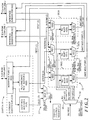
- FIG. 2 depicts a functional block diagram of switch 16 useful in the processing nodes 11(n), which alleviates the deadlock problem.
- the switch 16 includes a plurality of interface subsystems 20(0) through 20(2) (generally identified by reference numeral 20(i)), a received message selection section 21, and a transmit message packet selection section 22, all controlled by a switch control module 23.
- Each ofthe interface subsystems 20(i) is connected to one of the two communication links 12(n) and 12(n-1) (index "n-1" taken modulo “8") or communication link 13(n)(n+4) connected to the processing node 11(n), and receives message packets that are transmitted to the processing node 11(n) over the respective communication link and transmits message packets over the respective communication link.
- received message selection section 21 selectively couples the message packets to other portions of the processing node 11(n) for processing, such as to the processor 14, memory 15 or to other elements (not shown) of the processing node 11(n) as enabled by the processor 14. If multiple message packets are concurrently received by two or more interface subsystems 20(i), the received message selection section 21, under control of the switch control module, couples successive message packets serially to the other portions of the processing node for processing.
- the transmit message packet selection section 22 selectively couples message packets received by the interface subsystems 20(i) for which the processing node 11(n) is an intermediate processing node, as well as message packets to be injected by the processing node, to respective ones of the interface subsystems 20(i) for transmission.
- the transmit message packet selection section 22 will enable the message packet to be coupled to a respective interface subsystem 20(1) or 20(2) for transmission.
- the transmit message packet selection section 22 will enable the message packet to be coupled to respective interface subsystem 20(0) or 20(2) for transmission.
- the transmit message packet selection section 22 will enable the message packet to be coupled to respective interface subsystem 20(0) or 20(1) for transmission.
- the transmit message packet selection section 22 controls the injection by the processing node 11(n) of message packets into the interconnection subsystem, that is, message packets for which the processing node 11(n) itself is the source processing node.
- message packets may be provided by the processing node's processor 14, or they may be retrieved by the switch 16 from, for example, the memory 15 if the switch 16 can retrieve information from the memory in a "direct memory access" procedure.
- the transmit message packet selection section 22 will couple each such message packet to one of the respective interface subsystems 20(i) for transmission.
- the interface subsystem 20(0) includes an interface port 30(0), a destination receive buffer 31(0) and an intermediate receive buffer 32(0). For each message packet that is received by the processing node 11(n) over the communication link "0," the interface port 30(0) couples the message packet to one of the destination receive buffer 31(0) or the intermediate receive buffer 32(0).
- the interface port 30(0) receives a message packet for which the processing node 11(n) is the destination processing node, it (that is, the interface port 30(0)) will couple the message packet to the destination receive buffer 31(0), which will buffer the packet until it (that is, the packet) is transferred by the received message packet selection section 21 to other portions of the processing node 11(n) for processing as described above.
- the interface port 30(0) receives a message packet for which the processing node 11(n) is an intermediate processing node, it (that is, the interface port 30(0)) will couple the message packet to the intermediate receive buffer 32(0), which will buffer the packet until it (that is, the packet) is transferred by the transmit message packet selection section 22 to the appropriate interface subsystem 21(1) or 21(2) for transmission as described above.
- each message packet comprises a selected number of successively-received words
- each of the buffers 31(0) and 32(0) essentially comprises a queue in which the successive words of the respective message packets are stored.
- each of the buffers 31(0) and 32(0) has sufficient capacity to store words for one message packet.
- the destination receive buffer 31(0) buffers each message packet received by the interface subsystem 20(0) for which the processing node 11(n) is the destination processing node. Under control of the switch control module 23, the destination receive buffer 31(0), will couple the successive words of the buffered message packet to the received message packet selection section 21 as a DEST(0) destination signal.
- the interface subsystems 20(1) and 20(2), connected to the other communication links to which the processing node 11(n) is connected are similar to the interface subsystem 20(0), and when they receive message packets over their respective communication links for which the processing node 11(n) is the destination processing node, the message packets will be buffered in their respective destination receive buffers (not shown).
- the switch control module 23 can control the respective destination receive buffers to enable the buffered packets to be coupled to the received message packet selection section as respective DEST(1) and DEST(2) destination signals.
- the intermediate receive buffer 32(0) buffers each message packet received by the interface subsystem 20(0) for which the processing node 11(n) is an intermediate processing node. Under control ofthe switch control module 23, the intermediate receive buffer 32(0), will couple the successive words of the buffered message packet to the transmit message packet selection section 22 as a INTERM(0) intermediate signal.
- the interface subsystems 20(1) and 20(2), connected to the other communication links to which the processing node 11(n) is connected are similar to the interface subsystem 20(0), and when they receive message packets over their respective communication links for which the processing node 11(n) is an intermediate processing node, the message packets will be buffered in their respective intermediate receive buffers (not shown).
- the switch control module 23 can control the respective intermediate receive buffers to enable the buffered packets to be coupled to the transmit message packet selection section 22 as respective INTERM(1) and INTERM(2) destination signals.
- the received message packet selection section 21 under control of the switch control module 23, receives the message packets buffered by the destination receive buffers 31(0) through 31(2) and couples them to other portions of the processing node 11(n) for storage or processing.
- the received message packet selection section 21 comprises a multiplexer 33 that is controlled in response to a SEL REC PORT selected receive port signal from the switch control module 23.
- the switch control module 23 in addition to controlling the destination receive buffers of the respective interface subsystems 20(0) through 20(2), will concurrently control the SEL REC PORT selected receive port signal to enable the multiplexer 33 to, in turn, selectively couple one of the DEST(0) through DEST(2) destination signals from the interface subsystems 20(0) through 20(2) as a SEL DEST selected destination signal, which may be coupled to the processor 14 (FIG. 1).
- the switch control module 23 if the switch control module 23 enables the destination receive buffer 31(0) of interface subsystem 20(0) to couple the message packet buffered therein as the DEST(0) destination signal as described above, it (that is, the switch control module 23) will contemporaneously control the SEL REC PORT selected receive port signal to enable the multiplexer 33 to couple the DEST(0) destination signal as the SEL DEST selected destination signal to, for example, the processor 14.
- the switch control module 23 if the switch control module 23 enables the destination receive buffer (not shown) of interface subsystem 20(1) or 20(2) to couple the respective message packet buffer therein as the DEST(1) or DEST(2) destination signal as described above, it (that is, the switch control module 23) will contemporaneously control the SEL REC PORT selected receive port signal to enable the multiplexer 33 to couple the respective DEST(1) or DEST(2) destination signal to, for example, the processor 14.
- the transmit message packet selection section 22 comprises a injected message communication link selector 34 and a plurality of transmit message packet selectors 35(0) through 35(2) (generally identified by reference numeral 35(i)), with each transmit message packet selector 35(i) being associated with the correspondingly-indexed interface subsystem 20(i).
- the injected message communication link selector 34 comprises a demultiplexer 36 that receives an INJ MSG injected message signal, representing a message packet received from, for example, processor 14, memory 15 or other element of the processing node, and, under control of a SEL INJ MSG XMT PORT selected injected message transmit port signal from the switch control module 23, couples the INJ MSG injected message signal as a selected one of INJ MSG (0) through INJ MSG (2) injected message (0) through (2) signals to one of the transmit message packet selectors 35(0) through 35(2).
- an INJ MSG injected message signal representing a message packet received from, for example, processor 14, memory 15 or other element of the processing node
- SEL INJ MSG XMT PORT selected injected message transmit port signal from the switch control module 23
- couples the INJ MSG injected message signal as a selected one of INJ MSG (0) through INJ MSG (2) injected message (0) through (2) signals to one of the transmit message packet selectors 35(0) through 35(2).
- the SEL INJ MSG XMT PORT selected injected message transmit port signal from the switch control module 23 will control the demultiplexer 36 to couple the INJ MSG injected message signal as the INJ MSG (0) injected message (0) signal to transmit message packet selector 35(0).
- the SEL INJ MSG XMT PORT selected injected message transmit port signal from the switch control module 23 will control the demultiplexer 36 to couple the INJ MSG injected message signal as the respective INJ MSG (1) or INJ MSG (2) injected message (1) or (2) signal to respective transmit message packet selector 35(1) or 35(2).
- Each transmit message packet selector 35(i) includes an intermediate packet multiplexer 40(i), an transmit packet multiplexer 41(i) and an injected message packet buffer 42(i). Injected message packets coupled to the respective transmit message packet selector 35(i) by the multiplexer 36 are buffered in the injected message packet buffer 42(i).
- the intermediate packet multiplexer 40(i) receives the INTERM (i') and INTERM (i") (i', i" ⁇ i) intermediate signals from the interface subsystems 20(i') and 20(i") (i', i" ⁇ i) and, under control of a SEL INT i'/i" (i', i" ⁇ i) select intermediate signal from the switch control module 23, couples one of the received INTERM (i') and INTERM (i") intermediate signals to one input of the transmit packet multiplexer 41(i).
- the INTERM (i') and INTERM (i") intermediate signals represent message packets buffered in the intermediate receive buffers of the interface subsystems 20(i')and 20(i"), and so the signal coupled by the intermediate packet multiplexer 40(i) to the transmit packet multiplexer 41(i) represent a packet from the respective intermediate receive buffer.
- the XMIT MSG PORT (i) transmit message port (i) signal is provided directly to the interface port of the respective interface subsystem 20(i) for transmission.
- the intermediate packet multiplexer 40(0) receives the INTERM (1) and INTERM (2) intermediate signals from the interface subsystems 20(1) and 20(2) and, under control of a SEL INT 1/2 select intermediate signal from the switch control module 23, couples one of the INTERM (1) and INTERM (2) intermediate signals to one input of the transmit packet multiplexer 41(0).
- the INTERM (1) and INTERM (2) intermediate signals represent message packets buffered in the intermediate receive buffers of the interface subsystems 20(1) and 20(2), and so the signal coupled by the intermediate packet multiplexer 40(0) to the transmit packet multiplexer 41(0) represent a packet from intermediate receive buffer 20(1) or 20(2).
- the transmit packet multiplexer 41(0) of the transmit message packet selector 35(0) under control of the switch control module 23, selectively couples the selected intermediate message packet, represented by the signal from the intermediate packet multiplexer 40(0) or an injected packet that is buffered in injected packet buffer 42(0) as a XMIT MSG PORT (0) transmit message port (0) signal to the interface subsystem 20(0) connected thereto for transmission over the respective communication link.
- the XMIT MSG PORT (0) transmit message port (0) signal is provided directly to the interface port 30(0) of the interface subsystem 20(0) for transmission.
- the transmit message packet selectors 35(1) and 35(2) are constructed and operate in a similar manner in connection with the respective INTERM (0) through INTERM (2) intermediate signals and INJ MSG (1) and INJ MSG (2) injected message signals coupled thereto.
- the processing node 11(n) Since all of the interface subsystems 20(i) include buffers for buffering message packets received by the processing node 11(n) over the communication links connected thereto, as well as separate injected message buffers for buffering message packets to be injected by the processing node 11(n), the processing node 11(n) will have sufficient buffering resources to ensure both that the processing node 11(n) can inject a message and receive messages from processing nodes 11(n+1), 11(n-1) and 11(n+4) adjacent thereto, concurrently.
- each interface subsystem 20(i) includes both a buffer for buffering message packets for which the processing node 11(n) is the destination (that is, the destination receive buffer 31(i)) and a buffer for buffering message packets to be forwarded to another processing node 11(n')(n' ⁇ n) (that is, the intermediate receive buffer 32(i)), receipt and buffering of message packet by one interface subsystem 20(i) for which the processing node 11(n) is the destination processing node will not block subsequent receipt and buffering of a subsequent message packet by the same interface subsystem 20(i) for which the processing node 20(n) is an intermediate processing node. Accordingly, the switch 16 ensures that deadlocks cannot occur in the interconnection subsystem for the multiprocessor computer system 10.
- the system 10 has been described as comprising processing nodes interconnected by communication links in a Moebius strip topology of diameter two, it will be appreciated that the processing nodes may be interconnected in any cyclic topology of any diameter.
- D system of diameter
- D ⁇ 2 "D" hops will be required to transfer a message packet from any processing node 11(n) in the system to any other processing node 11(n')(n' ⁇ n).
- the switch 16 each ofthe interface ports 20(i) will be provided with "D-1" intermediate receive buffers, each of which can be deemed associated with a hop.
- the message packet will proceed through intermediate receive buffers associated with successive hops. That is, when a processing node 11(n) receives the message packet for the "h-th” hop, the message packet can be stored in the "h-th" intermediate receive buffer, until the destination processing node receives the message packet. When the destination processing node receives the message packet, the message packet will be buffered in the destination receive buffer 31(i) (FIG. 2). In general, if "D-1" intermediate receive buffers are provided for processing nodes interconnected in a cyclic topology of diameter "D,” deadlock can be avoided for any message transfer.
- the embodiment has been described in connection with a plurality of processing nodes whose switches 16 are of degree three, it will be appreciated that the techniques can be used in connection with processing nodes whose switches of other degrees.
- the invention will be used in connection with systems in which the processing nodes are interconnected in a cyclic topology, which can be accomplished using processing nodes of degree other that three.
- the minimum number of interface subsystems 20(i) and transmit message packet selectors 35(i) (FIG. 2) in a processing node's switch 16 will generally at least correspond to the switch's degree.
- each bidirectional communication link can be implemented using two unidirectional communication links which transfer message packets in opposite directions between respective pairs of processing nodes 11(n), 11(n+1) and 11(n), 11(n+4).
- at least some of the communication links 12(n) and 13(n)(n+4) can comprise single unidirectional communication links, which transfer message packets in only one direction between respective pairs of processing nodes.
- each interface subsystem 20(i) of the respective processing nodes 11(n) have been described as including destination receive buffers 31(i) and intermediate receive buffers 32(i) for receiving entire message packets before forwarding them through the received message selection section 21 to other elements of the respective processing node 11(n), or through the transmit message packet selection section 22 to a respective interface subsystems 20(i') (i' ⁇ i) for transfer to another processing node 11(n')(n' ⁇ n), it will be appreciated that some or all of the respective buffers may alternatively be constructed to receive only a portion of the respective packets before forwarding them.
- the embodiment has been described in connection with a system 10 comprising processing nodes 11(n) all of which have similar general structures, it will be appreciated that the techniques may be used in connection with a system including nodes of diverse structures. Indeed, at least some nodes may be connected only to input/output devices, such as mass storage subsystems, network interfaces, interfaces to the public telephony system, hardcopy output devices and the like.
- the embodiments may be used in connection with a message packet transfer system comprising switching nodes, which may be similar to switches 16 of the processing nodes 11(n) described above, with the switching node being connected to any type of source for providing message packets for transmission or destination for receiving message packets. Other arrangements will be apparent to those skilled in the art.
- the switch 16 has been described as including a received message selection section 21, if the outputs of the destination receive buffers 31(i) of the respective interface subsystems 20(i) can be connected together in a "wired OR" connection, the received message selection section 21 can be eliminated. In that case, the switch control module 23 can generate gating signals to enable the respective destination receive buffers to gate the message packets buffered therein as the SEL DEST selected destination signal.
- the switch 16 has been described as including the injected message communication link selector 34 including demultiplexer 36, it will be appreciated that the INJ MSG injected message signal may instead be coupled to the inputs of each of the injected message buffers 42(i), and the switch control module 23 may generate appropriate load enable signals to enable the appropriate injected message buffer 42(i) to receive and buffer the message packet to be injected.
- transmit message packet selectors 35(i) are described as including two separate multiplexers 40(i) and 41(i), it will be appreciated that the multiplexers 40(i) and 41(i) may be combined into a single multiplexer for selectively coupling the respective INTERM (i'), INTERM (i") (i', i" ⁇ i) signal, representing the message packets from the respective intermediate receive buffers 32(i'), 32(i"), or the buffered injected message packet from the injected message buffer 42(i), as the XMIT MSG PORT (i) transmit message port (i) signal.
- a system in accordance with the invention can be constructed in whole or in part from special purpose hardware or a general purpose computer system, or any combination thereof, any portion of which may be controlled by a suitable program.
Landscapes
- Engineering & Computer Science (AREA)
- Computer Networks & Wireless Communication (AREA)
- Signal Processing (AREA)
- Data Exchanges In Wide-Area Networks (AREA)
- Multi Processors (AREA)
Applications Claiming Priority (2)
| Application Number | Priority Date | Filing Date | Title |
|---|---|---|---|
| US08/674,277 US5878227A (en) | 1996-07-01 | 1996-07-01 | System for performing deadlock free message transfer in cyclic multi-hop digital computer network using a number of buffers based on predetermined diameter |
| US674277 | 1996-07-01 |
Publications (2)
| Publication Number | Publication Date |
|---|---|
| EP0817437A2 true EP0817437A2 (de) | 1998-01-07 |
| EP0817437A3 EP0817437A3 (de) | 2003-08-20 |
Family
ID=24706009
Family Applications (1)
| Application Number | Title | Priority Date | Filing Date |
|---|---|---|---|
| EP97304722A Withdrawn EP0817437A3 (de) | 1996-07-01 | 1997-06-30 | Nachrichtenübertragung in Rechnernetze |
Country Status (2)
| Country | Link |
|---|---|
| US (2) | US5878227A (de) |
| EP (1) | EP0817437A3 (de) |
Families Citing this family (25)
| Publication number | Priority date | Publication date | Assignee | Title |
|---|---|---|---|---|
| US8621101B1 (en) | 2000-09-29 | 2013-12-31 | Alacritech, Inc. | Intelligent network storage interface device |
| US6226680B1 (en) | 1997-10-14 | 2001-05-01 | Alacritech, Inc. | Intelligent network interface system method for protocol processing |
| US8539112B2 (en) | 1997-10-14 | 2013-09-17 | Alacritech, Inc. | TCP/IP offload device |
| US6434620B1 (en) * | 1998-08-27 | 2002-08-13 | Alacritech, Inc. | TCP/IP offload network interface device |
| US6697868B2 (en) * | 2000-02-28 | 2004-02-24 | Alacritech, Inc. | Protocol processing stack for use with intelligent network interface device |
| US8782199B2 (en) * | 1997-10-14 | 2014-07-15 | A-Tech Llc | Parsing a packet header |
| US6757746B2 (en) * | 1997-10-14 | 2004-06-29 | Alacritech, Inc. | Obtaining a destination address so that a network interface device can write network data without headers directly into host memory |
| US6185631B1 (en) | 1998-10-14 | 2001-02-06 | International Business Machines Corporation | Program for transferring execution of certain channel functions to a control unit and having means for combining certain commands and data packets in one sequence |
| US6230218B1 (en) * | 1998-10-14 | 2001-05-08 | International Business Machines Corporation | Apparatus for transferring execution of certain channel functions to a control unit and having means for combining certain commands and data packets in one sequence |
| US6330585B1 (en) | 1998-10-14 | 2001-12-11 | International Business Machines Corporation | Transfer information using optical fiber connections |
| US6240446B1 (en) | 1998-10-14 | 2001-05-29 | International Business Machines Corporation | Multiplexing of multiple data packets for multiple input/output operations between multiple input/output devices and a channel subsystem having multiple channels |
| US6609165B1 (en) | 1999-09-27 | 2003-08-19 | International Business Machines Corporation | Method and apparatus for using fibre channel extended link service commands in a point-to-point configuration |
| US6499066B1 (en) | 1999-09-27 | 2002-12-24 | International Business Machines Corporation | Method and apparatus for using fibre channel test extended link service commands for interprocess communication |
| US8019901B2 (en) | 2000-09-29 | 2011-09-13 | Alacritech, Inc. | Intelligent network storage interface system |
| EP1333689A1 (de) * | 2002-02-04 | 2003-08-06 | Siemens Aktiengesellschaft | Routingverfahren und -system mit bedingtem Logging |
| US7543087B2 (en) * | 2002-04-22 | 2009-06-02 | Alacritech, Inc. | Freeing transmit memory on a network interface device prior to receiving an acknowledgement that transmit data has been received by a remote device |
| US7010471B2 (en) * | 2003-01-17 | 2006-03-07 | At&T Corp. | Hierarchical topological network designing system and method |
| US6996070B2 (en) * | 2003-12-05 | 2006-02-07 | Alacritech, Inc. | TCP/IP offload device with reduced sequential processing |
| US8248939B1 (en) | 2004-10-08 | 2012-08-21 | Alacritech, Inc. | Transferring control of TCP connections between hierarchy of processing mechanisms |
| US7849256B2 (en) * | 2006-07-11 | 2010-12-07 | Advanced Micro Devices, Inc. | Memory controller with ring bus for interconnecting memory clients to memory devices |
| US20080263171A1 (en) * | 2007-04-19 | 2008-10-23 | Alacritech, Inc. | Peripheral device that DMAS the same data to different locations in a computer |
| US7944842B2 (en) * | 2007-04-20 | 2011-05-17 | International Business Machines Corporation | Opportunistic queueing injection strategy for network load balancing |
| US8539513B1 (en) | 2008-04-01 | 2013-09-17 | Alacritech, Inc. | Accelerating data transfer in a virtual computer system with tightly coupled TCP connections |
| US8341286B1 (en) | 2008-07-31 | 2012-12-25 | Alacritech, Inc. | TCP offload send optimization |
| US9306793B1 (en) | 2008-10-22 | 2016-04-05 | Alacritech, Inc. | TCP offload device that batches session layer headers to reduce interrupts as well as CPU copies |
Family Cites Families (14)
| Publication number | Priority date | Publication date | Assignee | Title |
|---|---|---|---|---|
| US4616359A (en) * | 1983-12-19 | 1986-10-07 | At&T Bell Laboratories | Adaptive preferential flow control for packet switching system |
| KR900006793B1 (ko) * | 1984-10-18 | 1990-09-21 | 휴우즈 에어크라프트 캄파니 | 패킷 스위치 다중 대기행렬 NxM 스위치 노오드 및 처리 방법 |
| US4742511A (en) * | 1985-06-13 | 1988-05-03 | Texas Instruments Incorporated | Method and apparatus for routing packets in a multinode computer interconnect network |
| US4780870A (en) * | 1986-09-05 | 1988-10-25 | American Telephone And Telegraph Company, At&T Bell Laboratories | Packet switch |
| JPH088572B2 (ja) * | 1987-03-09 | 1996-01-29 | 株式会社日立製作所 | 通信システムにおけるノード装置 |
| ATE86055T1 (de) * | 1987-11-11 | 1993-03-15 | Siemens Ag | Vermittlungsknoten fuer die vermittlung von in datenpaketen uebertragenen datensignalen. |
| US5347450A (en) * | 1989-01-18 | 1994-09-13 | Intel Corporation | Message routing in a multiprocessor computer system |
| DE69330661T2 (de) * | 1992-04-27 | 2002-06-27 | Nippon Telegraph And Telephone Corp., Tokio/Tokyo | Paketnetzwerk und Verfahren zur Vermeidung von Überlastung eines solchen Netzwerks |
| US5444701A (en) * | 1992-10-29 | 1995-08-22 | International Business Machines Corporation | Method of packet routing in torus networks with two buffers per edge |
| US5583990A (en) * | 1993-12-10 | 1996-12-10 | Cray Research, Inc. | System for allocating messages between virtual channels to avoid deadlock and to optimize the amount of message traffic on each type of virtual channel |
| US5544154A (en) * | 1995-03-09 | 1996-08-06 | Telefonaktiebolaget Lm Ericsson | Method for determining the load induced by a routing verification test on a network |
| JP2770782B2 (ja) * | 1995-05-31 | 1998-07-02 | 日本電気株式会社 | Lan間接続装置 |
| US5838994A (en) * | 1996-01-11 | 1998-11-17 | Cisco Technology, Inc. | Method and apparatus for the dynamic allocation of buffers in a digital communications network |
| US5907717A (en) * | 1996-02-23 | 1999-05-25 | Lsi Logic Corporation | Cross-connected memory system for allocating pool buffers in each frame buffer and providing addresses thereof |
-
1996
- 1996-07-01 US US08/674,277 patent/US5878227A/en not_active Ceased
-
1997
- 1997-06-30 EP EP97304722A patent/EP0817437A3/de not_active Withdrawn
-
2001
- 2001-03-02 US US09/798,283 patent/USRE38650E1/en not_active Expired - Lifetime
Also Published As
| Publication number | Publication date |
|---|---|
| US5878227A (en) | 1999-03-02 |
| EP0817437A3 (de) | 2003-08-20 |
| USRE38650E1 (en) | 2004-11-09 |
Similar Documents
| Publication | Publication Date | Title |
|---|---|---|
| US5878227A (en) | System for performing deadlock free message transfer in cyclic multi-hop digital computer network using a number of buffers based on predetermined diameter | |
| EP0197103B1 (de) | Belastungsausgleich für paketvermittlungsknoten | |
| US5289303A (en) | Chuted, optical packet distribution network | |
| JPH08185380A (ja) | 並列計算機 | |
| EP0405208B1 (de) | Mehrstufiges Netz mit verteilter Steuerung | |
| JPH10294729A (ja) | 交差接続マルチレート/マルチキャストsdh/sonet再配置手順およびこれを使用した交差接続 | |
| EP0590865B1 (de) | Mehrstufige erweiterbare optische Paketverteilanordnung mit Überbrückungsschalter | |
| RU2129751C1 (ru) | Коммутационная система для выполнения асинхронного режима передачи и способ коммутации ячеек в ней | |
| US7151752B2 (en) | Method for the broadcasting of a data packet within a switched network based on an optimized calculation of the spanning tree | |
| CZ385391A3 (en) | Communication system | |
| US5848059A (en) | Node device used in network system for packet communication, network system using such node devices, and communication method used therein | |
| US5420982A (en) | Hyper-cube network control system having different connection patterns corresponding to phase signals for interconnecting inter-node links and between input/output links | |
| EP0142332B1 (de) | Verbindungsnetzwerke | |
| JP2976675B2 (ja) | アレイプロセッサのルーティング方法 | |
| JP2960454B2 (ja) | 並列プロセッサのプロセッサ間データ転送装置 | |
| AU700139B2 (en) | Multi-node data processing system | |
| EP0446492B1 (de) | Kommunikations-Vermittlungsmodul | |
| Flammini et al. | Simple, efficient routing schemes for all-optical networks | |
| CA1280497C (en) | Switching element for self-routing multistage packet- switching interconnection networks | |
| JPS63135039A (ja) | 待ち合わせ形スイツチ網の経路選択制御方法 | |
| JPH0136139B2 (de) | ||
| KR0159365B1 (ko) | 바이패싱 기능을 갖는 에이티엠 셀 분배 및 집속장치 | |
| Salisbury et al. | Multicast control in optical circuit-switched Banyan networks | |
| Lang et al. | A new analysis for wavelength translation in regular WDM networks | |
| Padmanabhan | A shuffle-based alternative to the ADM interconnection architecture |
Legal Events
| Date | Code | Title | Description |
|---|---|---|---|
| PUAI | Public reference made under article 153(3) epc to a published international application that has entered the european phase |
Free format text: ORIGINAL CODE: 0009012 |
|
| AK | Designated contracting states |
Kind code of ref document: A2 Designated state(s): AT BE CH DE DK ES FI FR GB GR IE IT LI LU MC NL PT SE |
|
| RIN1 | Information on inventor provided before grant (corrected) |
Inventor name: HELLER, STEVEN K. Inventor name: WADE, JON P |
|
| RAP1 | Party data changed (applicant data changed or rights of an application transferred) |
Owner name: SUN MICROSYSTEMS, INC. |
|
| PUAL | Search report despatched |
Free format text: ORIGINAL CODE: 0009013 |
|
| AK | Designated contracting states |
Designated state(s): AT BE CH DE DK ES FI FR GB GR IE IT LI LU MC NL PT SE |
|
| RIC1 | Information provided on ipc code assigned before grant |
Ipc: 7H 04L 12/54 B Ipc: 7H 04L 12/42 B Ipc: 7H 04L 12/56 A |
|
| AKX | Designation fees paid | ||
| REG | Reference to a national code |
Ref country code: DE Ref legal event code: 8566 |
|
| STAA | Information on the status of an ep patent application or granted ep patent |
Free format text: STATUS: THE APPLICATION IS DEEMED TO BE WITHDRAWN |
|
| 18D | Application deemed to be withdrawn |
Effective date: 20040221 |