EP0817867B1 - Vorrichtung zum abdichten einer lanze in einer öffnung zum durchführen der lanze in einen unter druck stehenden behälter - Google Patents
Vorrichtung zum abdichten einer lanze in einer öffnung zum durchführen der lanze in einen unter druck stehenden behälter Download PDFInfo
- Publication number
- EP0817867B1 EP0817867B1 EP96907411A EP96907411A EP0817867B1 EP 0817867 B1 EP0817867 B1 EP 0817867B1 EP 96907411 A EP96907411 A EP 96907411A EP 96907411 A EP96907411 A EP 96907411A EP 0817867 B1 EP0817867 B1 EP 0817867B1
- Authority
- EP
- European Patent Office
- Prior art keywords
- lance
- sealing device
- sealing
- piston
- pistons
- Prior art date
- Legal status (The legal status is an assumption and is not a legal conclusion. Google has not performed a legal analysis and makes no representation as to the accuracy of the status listed.)
- Expired - Lifetime
Links
- 238000007789 sealing Methods 0.000 title claims abstract description 81
- 238000012856 packing Methods 0.000 claims description 28
- 239000000463 material Substances 0.000 claims description 9
- 239000004033 plastic Substances 0.000 claims description 7
- 239000007789 gas Substances 0.000 description 7
- 238000005299 abrasion Methods 0.000 description 4
- 238000006073 displacement reaction Methods 0.000 description 4
- 239000000314 lubricant Substances 0.000 description 3
- 230000008602 contraction Effects 0.000 description 2
- 230000000694 effects Effects 0.000 description 2
- 238000003780 insertion Methods 0.000 description 2
- 230000037431 insertion Effects 0.000 description 2
- 239000007788 liquid Substances 0.000 description 2
- UGFAIRIUMAVXCW-UHFFFAOYSA-N Carbon monoxide Chemical compound [O+]#[C-] UGFAIRIUMAVXCW-UHFFFAOYSA-N 0.000 description 1
- 230000033228 biological regulation Effects 0.000 description 1
- 229910002091 carbon monoxide Inorganic materials 0.000 description 1
- 239000011248 coating agent Substances 0.000 description 1
- 238000000576 coating method Methods 0.000 description 1
- 238000010276 construction Methods 0.000 description 1
- 230000007797 corrosion Effects 0.000 description 1
- 238000005260 corrosion Methods 0.000 description 1
- 230000006378 damage Effects 0.000 description 1
- 230000007423 decrease Effects 0.000 description 1
- 230000006735 deficit Effects 0.000 description 1
- 239000013013 elastic material Substances 0.000 description 1
- 230000007613 environmental effect Effects 0.000 description 1
- 230000008676 import Effects 0.000 description 1
- 230000001050 lubricating effect Effects 0.000 description 1
- 238000005381 potential energy Methods 0.000 description 1
- 238000010926 purge Methods 0.000 description 1
- 230000003014 reinforcing effect Effects 0.000 description 1
- 239000000523 sample Substances 0.000 description 1
Images


Classifications
-
- F—MECHANICAL ENGINEERING; LIGHTING; HEATING; WEAPONS; BLASTING
- F27—FURNACES; KILNS; OVENS; RETORTS
- F27D—DETAILS OR ACCESSORIES OF FURNACES, KILNS, OVENS OR RETORTS, IN SO FAR AS THEY ARE OF KINDS OCCURRING IN MORE THAN ONE KIND OF FURNACE
- F27D99/00—Subject matter not provided for in other groups of this subclass
- F27D99/0073—Seals
-
- C—CHEMISTRY; METALLURGY
- C21—METALLURGY OF IRON
- C21B—MANUFACTURE OF IRON OR STEEL
- C21B7/00—Blast furnaces
- C21B7/24—Test rods or other checking devices
-
- F—MECHANICAL ENGINEERING; LIGHTING; HEATING; WEAPONS; BLASTING
- F16—ENGINEERING ELEMENTS AND UNITS; GENERAL MEASURES FOR PRODUCING AND MAINTAINING EFFECTIVE FUNCTIONING OF MACHINES OR INSTALLATIONS; THERMAL INSULATION IN GENERAL
- F16J—PISTONS; CYLINDERS; SEALINGS
- F16J15/00—Sealings
- F16J15/46—Sealings with packing ring expanded or pressed into place by fluid pressure, e.g. inflatable packings
-
- F—MECHANICAL ENGINEERING; LIGHTING; HEATING; WEAPONS; BLASTING
- F27—FURNACES; KILNS; OVENS; RETORTS
- F27D—DETAILS OR ACCESSORIES OF FURNACES, KILNS, OVENS OR RETORTS, IN SO FAR AS THEY ARE OF KINDS OCCURRING IN MORE THAN ONE KIND OF FURNACE
- F27D3/00—Charging; Discharging; Manipulation of charge
- F27D3/16—Introducing a fluid jet or current into the charge
Definitions
- This invention relates to a device for sealing a lance in a Opening for the passage of the lance into a pressurized container, especially a shaft furnace.
- sealing devices are provided which and allow execution of the lance, and thereby an escape of the gases prevent from the shaft furnace.
- the simplest form of the sealing device are plastically deformable packings, which are arranged in a tight housing and close to the Lance to be inserted, creating a seal against the housing is achieved.
- the cross section of the lance is relatively strong Fluctuations. These changes in the cross section of the lance can on the one hand, as a result of deposits or wear, which the cross section increases or downsized, on the other hand it gets through operational temperature fluctuations and the associated thermal expansion resp. Contraction to changes in cross-section of the Lance. However, these changes cause the plastic packs relatively quickly no longer fit snugly on the lance, causing the sealing Property is lost.
- a sealing device which is an elastic, inflatable seal includes the close to the lance inserted by pressurization Lance is in contact, but this is so far when inserting and executing the lance withdrawn that it is no longer on the lance.
- Ring seals e.g. Soft seals or packings, provided which constantly on the lance.
- the inflatable, elastic seal is no longer in contact with the lance in this phase radial play caused by changes in the cross section of the lance, can no longer be compensated.
- FR-A-1.600.190 describes e.g. a sealing device for one Trunnion, with inflatable seal, which is under pressure seals against the trunnion.
- the inflatable seal is in a ring arranged in a radial chamber in a housing, the ring in the housing is radially movable such that radial displacements between the pivot and the housing can be compensated.
- the device again has the disadvantage of being rapidly worn Hose seal, which has already been described above.
- DE-A-14 25 523 discloses a sealing device for rotating shafts, with two soft packs inside a case around the shaft are arranged, the packs by a spring tension standing open cage construction or by a coat from a light deformable material are kept in their axial position.
- the housing By loading of the housing with a pressure medium are the soft packs pressed in the radial direction against the sealing surface of the shaft and the contact pressure raised on the wave.
- US-A-2,273,129 deals with a seal for a roller bearing, in which two in a housing coaxial with a shaft Sealing rings with a U-shaped cross section arranged adjacent to the shaft are, the legs of the U-profile each form a sealing lip.
- the Seals are axially spaced such that the incisions axially opposed in the U-shaped cross sections, so that the incisions open into a pressure chamber formed between the seals.
- the two are pressurized with a pressure medium Sealing lips of each seal are pressed apart radially so that the on the shaft the sealing lip fits snugly against it.
- US-A-3,434,728 describes a device for sealing a shaft bushing in a Pressure chamber, with a housing connected in one piece to the pressure chamber, that extends coaxially to the shaft outside the pressure chamber. Internally of the housing are packings around each end face of the housing Shaft arranged, each countered by a sleeve-shaped piston the corresponding end face of the housing can be pressed.
- the present invention is therefore based on the object of a sealing device for sealing a lance when running into a to provide pressurized containers which are both radial Game due to changes in the cross section of the lance as well as dislocations compensate the lance axis with respect to the axis of the bushing can, without excessive wear and tear, the tightness of the device endanger.
- a device for Sealing a lance in an opening to pass the lance into one pressurized container in particular a shaft furnace, the one outer housing with a shaft furnace side and an environment side End wall, which are axially provided with a through opening for a lance, and comprises a sealing member disposed in the outer housing, and the is characterized in that the sealing member with an inner housing axial end walls with a through opening for the lance comprises, as well as at least one pack and at least one axially displaceable annular pistons that are coaxial within the inner housing are arranged to an axis of the inner housing that the pack in Direction of actuation of the piston between the piston and one of the end walls the inner housing is arranged that the pack by actuation of the piston axially against one of the end walls of the inner housing is compressible, the pack expanding radially and sealingly lance and that the inner housing in the outer housing is radially slidably mounted, so that the inner Housing together with the packing and the piston self-centering on
- packing is used here as a generic term. It goes without saying for the person skilled in the art that a package as described in the present invention is used, also from several axially side by side arranged packing rings can exist. In this case the individual packing rings against each other when the piston is actuated pressed, with a first packing rings against one of the end walls supports, while a second packing ring is in direct contact with the piston and transfers the piston pressure to the packing rings in between.
- the package according to the invention Since the package can be compressed by a piston, the package according to the invention has Device the property that the seal on variations of the lance cross section can be adjusted. In addition, Moving the lance in the device turned off the actuation of the piston will. This loosens the tight fit of the pack around the lance, and this can be moved with less frictional resistance.
- the tightness of the entire Device by correspondingly stronger or weaker actuation of the Pistons can be adapted to the conditions in the container.
- Words e.g. if the pressure in the container increases, the required higher tightness of the sealing device through greater actuation of the Reach piston.
- the radial displacement possibility of the inner housing in the second Housing allows the inner housing to look at an oblique or a adjust axially offset position of the lance in the sealing device.
- the inner housing can thus freely center on the lance if the Lance is inserted obliquely or axially offset in the sealing device.
- the sealing member comprises two pistons and two packages arranged coaxially to the axis of the device the two pistons being arranged axially between the two packings, so that when operated they act in opposite directions, and each of the Packs by a piston against one of the end walls of the interior Housing is compressible.
- the elastic element is on the packing when the piston pressure decreases endeavors to return to its original form. If the piston doesn't more is pressed when the pack is pressed together by the pistons released potential energy stored in the elastic element, and the Pack is stretched axially. This is linked to a radial contraction, which loosens the tight fit of the pack around the lance.
- the inside is Housing in an advantageous manner with ring-shaped soft seals on the End walls of the inner housing are attached against the end faces of the sealed outer housing.
- annular pressure chamber is formed between the two pistons. Furthermore, each of the pistons with an inner ring seal is radially inward sealed against a guide sleeve, which is attached coaxially to the axis and with an outer ring seal radially outward against the inner surface of the sealed inner housing, the annular pressure chamber is axially sealed, and the two pistons can be pressurized at the same time Pressure chamber can be operated with a medium.
- This version can be used on the ring seals with which each of the pistons radially inwards against the guide sleeve and radially outwards against the Inner surface of the first housing is sealed, can be dispensed with.
- a certain permanent pre-tensioning of the packs, and therefore one To ensure certain tightness can optionally be in the pressure chamber elastic means may be arranged between the pistons through which the pistons are operable.
- These elastic means can e.g. comprise a coil spring. By this spring, the pistons are then also with a certain force pressed against the packs when the pressure chamber is not under pressure stands. It should be noted that the spring force of the spring should be less than the spring force of the elastic means in the packs, as these otherwise the Do not undo (even partially) deformation of the package can.
- an elastic means e.g. a preloaded spiral spring ring or a pre-stressed ring made of elastic plastic around the wedge-shaped Elements arranged around the one on the wedge-shaped elements exerts radially inward force.
- Elastic means can be used as a restoring element for the wedge-shaped elements be arranged between the guide sleeve and the wedge-shaped elements, which are supported radially inwards on the guide sleeve and which radially inwards press on the outside against the wedge-shaped elements.
- the contact surfaces with which to coat the inner housing on the lance with a material that reduces the frictional resistance of the contact surfaces on the lance.
- FIG. 1 shows a section through an embodiment of a sealing device. It comprises an outer housing 2, the inside of several chambers 4-8 is divided, which are separated in the axial direction by ribs 10 and in which the individual sealing elements are arranged. That is axially in the middle Housing 2 and the ribs 10 with a through opening for a lance 12 provided, the width of the opening is dimensioned so that the lance 12 has a relatively large radial play in it.
- the device in Fig. 1 includes a central sealing member 14, which in the middle chamber 6 is attached, two further sealing elements 16, 18 in chambers 4 and 8.
- These can e.g. be of the type described in DE-A-44 15 219 and DE-A-44 15 221 are described. They include rings 20, 22, whose clear cross section is adapted to the cross section of the lance 12.
- They include rings 20, 22, whose clear cross section is adapted to the cross section of the lance 12.
- everyone of these rings 20 respectively. 22 is in its chambers 4, respectively. 8 attached so that it slidable perpendicular to the central axis 24 of the sealing device is.
- This possibility of displacement of the rings 20, 22 in their respective Chamber 4, 8 of the housing 2 allows the rings 20, 22 to attach to one oblique or axially offset position of the lance 12 in the sealing device adapt.
- the rings with the sealing elements can therefore on the Center lance 12 freely when the lance passes through the sealing device is inserted obliquely or axially offset.
- the rings 20, 22 provide holders for sealing packs or seals are on the lance 12.
- the ring 20 inside with a provided by two packing rings 26 existing package over which it the lance 12 rests.
- the ring 22 has an inflatable seal 30 which is housed in a cavity 32 of the ring 22. In the not inflated Position, this inflatable seal 30 is retracted into its cavity 32; this allows the lance 12 to be moved without the inflatable Seal 30 is damaged or worn. In the inflated position however, the inflatable seal 30 can have a significantly greater radial clearance compensate as the two packing rings 26 of the sealing element 16.
- the Ring 22 is advantageously over two packs 28, which are on both sides of the Cavity 32 are arranged on the lance 12. To put pressure on the Giving inflatable seal 30 is advantageously pressure on the Chamber 8 given.
- the central sealing member 14 is shown enlarged in Fig.2. It includes a inner housing 46 with a shaft furnace side and an environment side End wall, which is provided with a passage opening for a lance 12 are.
- This inner housing is in the middle chamber 6 of the outer Housing 2 attached so that it is perpendicular to the central axis 24th the sealing device is displaceable.
- This shift possibility of the inner housing 46 in the chamber 6 of the housing 2, as in the rings 20, 22, a free centering of the inner housing 46 on the Lance 12 when the lance is oblique or axial through the sealing device is introduced offset.
- the inner housing 46 On its two end walls is the inner housing 46 with ring seals 48, which is screwed into the end faces in a groove coaxial with the axis 24 sit, axially sealed against the ribs 10 of the outer housing 2.
- Within the housing 46 are coaxial with the axis 24 both shaft side as well as one consisting of two packing rings on the environment side Pack 50 arranged. These packs 50 are preferably on the respective End wall of the inner housing 46. They are dimensioned such that they rest against the lance 12 when it is inserted into the sealing device becomes.
- two annular pistons 52 are also provided in the housing 46.
- This Annular pistons 52 are located radially outward on the inner wall of the inner one Housing 46 guided while being guided inwardly by a guide sleeve 54 are guided, which is arranged coaxially to the axis 24, and the light Width is such that the lance in the sleeve 54 a certain radial play.
- the ring pistons are each through two ring seals 56, e.g. O-rings or quad-rings, radially against the inner housing 46 and the guide sleeve 54 sealed, causing axial movement between the pistons Towards a sealed pressure chamber 58 is formed.
- the pressure chamber 58 becomes pressurized acted upon. This is preferably done in that the ring seals 48 sealed chamber 6 via a supply opening 60 with a Media is supplied.
- the chamber 6 is through openings 62 in the Housing 46 communicates with the pressure chamber 58, causing the pressure medium enters the pressure chamber 58. It should be noted that the pressurization the pressure chamber 58 by a pressurized liquid or a gas under pressure can be exported.
- the annular piston 52 are axially displaceable so that when actuated one of the pistons against the front wall of the shaft furnace Pack presses while the other piston pushes against the one on the ambient side Press against the bulkhead.
- the packs 50 are subjected to axial pressure against the respective end wall of the inner housing 46 pressed and axially compressed, being expand radially. This causes the packs to move closer to the lance 12 create, which increases the tightness of the entire device.
- a certain permanent pre-tensioning of the packs, and therefore one To ensure a certain degree of tightness can optionally be in the pressure chamber 58 between the two pistons 52 an elastic means 66, e.g. a coil spring, be arranged. This is shown in Fig.3.
- an elastic means 66 e.g. a coil spring, be arranged.
- the spring 66 By this spring 66, the Even then, the piston is pressed against the packs with a certain force, when the pressure chamber 58 is not under pressure.
- the Spring force of the spring 66 should be less than the spring force of the elastic Means 46 in the packs 50, since these otherwise the deformation of the Can not (even partially) undo the package.
- FIGS show a further variant of the sealing member 14.
- the entire pressure chamber 58 is elastic Seal 68 knocked out with an insert 70 in the interior Housing 46 is clamped.
- This seal 68 is the same as in FIGS previous embodiments pressurized. Since the Seal 68 is supported radially towards axis 24 against guide sleeve 54, it expands in the axial direction, whereby the two pistons 52 in turn operated simultaneously.
- the sealing member 14 shows a further possible embodiment, the sealing member 14.
- the two pistons 52 are made solely by an elastic means 72 operated.
- the sealing member turns up thereby automatically in fluctuations in the cross section of the lance.
- FIG. 6 Another externally controllable variant is presented in Fig. 6.
- the two pistons 52 actuated by means of wedge-shaped elements 74, which between the two pistons 52 are attached such that they are displaced by radial displacement axially push the two pistons 52 towards each other.
- Radial outwardly, the actuating elements 74 also have a section 76 mutually parallel side surfaces. On these side surfaces are the Elements 74 guided in a guide opening 78 in the inner housing 46 and sealed against them by means of soft seals 80.
- the wedge-shaped elements 74 are actuated by pressurizing the Chamber 6 via the inlet opening 60.
- the building up in the chamber Overpressure acts on the outer side surface of the wedge-shaped elements 74 and exerts a radially inward force on it.
- elastic means 82 advantageously a spiral spring that extends radially inward on the guide sleeve 54 supports, and the radially outward against the inner surface of the actuating element 74 presses. So that the actuators when the chamber 6 is depressurized 74 by the spring 82 not radially outwards from the guide openings 78 are pushed out, there are 78 stops on the outside of the guide openings 84 provided.
- a further variant can be implemented based on the embodiment of FIG that automatically adapts to changes in cross-section.
- This is shown in Fig.7.
- the wedge-shaped elements 74 are actuated no longer by pressurizing the chamber 6, but by a elastic element 86, the outside around the wedge-shaped actuators 74 is laid.
- This elastic element 86 can e.g. a spiral spring washer or a ring made of an elastic plastic that is biased in one annular groove 88 is attached, which is coaxial to the axis in the sections 76th of the actuators 74 radially inward from the outer side surface is executed.
- the Soft seals 80 become superfluous, as does the inlet opening 60.
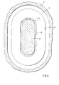
- Figure 8 shows a cross section along the line A-A 'in Figure 1 perpendicular to Axis through a sealing device with inserted lance 12. It can be seen that the lance 12 and thus the through opening in this case none have a circular cross-section, but a non-circular cross-section. However, this is only one possible embodiment, of course the Lance cross section also be circular.
- the lance 12 In the center of the arrangement, the lance 12 can be seen, which extends into the passage opening 90 is inserted into the inner housing 46 such that between the lance 12 and the inner housing 46 some play is.
- the chamber 6 passing inwards through the inner housing 46 and outwards is limited by the outer housing 2.
- the inner surface of the through opening 90 is in your upper area coated with a material 92 that has particularly good sliding properties.
- This material 92 with the rest of the upper parts of the Inner surfaces of the rings 20, 22 are coated, reduces the friction of the Rings 20, 22 respectively. of the sealing member 14 on the lance, and thus prevents the rapid wear of the areas that when centering the rings 20, 22 and. of the sealing member 14 rest on the lance 12 and on this back and forth.
Landscapes
- Engineering & Computer Science (AREA)
- General Engineering & Computer Science (AREA)
- Mechanical Engineering (AREA)
- Chemical & Material Sciences (AREA)
- Materials Engineering (AREA)
- Manufacturing & Machinery (AREA)
- Architecture (AREA)
- Physics & Mathematics (AREA)
- Metallurgy (AREA)
- Organic Chemistry (AREA)
- Fluid Mechanics (AREA)
- Sealing Devices (AREA)
- Furnace Details (AREA)
- Pressure Vessels And Lids Thereof (AREA)
- Auxiliary Methods And Devices For Loading And Unloading (AREA)
- Containers And Packaging Bodies Having A Special Means To Remove Contents (AREA)
- Nozzles (AREA)
- Encapsulation Of And Coatings For Semiconductor Or Solid State Devices (AREA)
- Spinning Methods And Devices For Manufacturing Artificial Fibers (AREA)
Applications Claiming Priority (3)
| Application Number | Priority Date | Filing Date | Title |
|---|---|---|---|
| LU88600A LU88600A1 (de) | 1995-03-31 | 1995-03-31 | Vorrichtung zum Abdichten einer Lanze in einer Oeffnung zum Durchfuehren der Lanze in einen unter Druck stehenden Behaelter |
| LU88600 | 1995-03-31 | ||
| PCT/EP1996/001018 WO1996030548A1 (de) | 1995-03-31 | 1996-03-09 | Vorrichtung zum abdichten einer lanze in einer öffnung zum durchführen der lanze in einen unter druck stehenden behälter |
Publications (2)
| Publication Number | Publication Date |
|---|---|
| EP0817867A1 EP0817867A1 (de) | 1998-01-14 |
| EP0817867B1 true EP0817867B1 (de) | 1998-11-04 |
Family
ID=19731522
Family Applications (1)
| Application Number | Title | Priority Date | Filing Date |
|---|---|---|---|
| EP96907411A Expired - Lifetime EP0817867B1 (de) | 1995-03-31 | 1996-03-09 | Vorrichtung zum abdichten einer lanze in einer öffnung zum durchführen der lanze in einen unter druck stehenden behälter |
Country Status (15)
| Country | Link |
|---|---|
| EP (1) | EP0817867B1 (cs) |
| KR (1) | KR19980703332A (cs) |
| CN (1) | CN1049923C (cs) |
| AT (1) | ATE173025T1 (cs) |
| AU (1) | AU5105096A (cs) |
| BR (1) | BR9607993A (cs) |
| CA (1) | CA2216951A1 (cs) |
| CZ (1) | CZ285733B6 (cs) |
| DE (1) | DE59600782D1 (cs) |
| ES (1) | ES2124091T3 (cs) |
| LU (1) | LU88600A1 (cs) |
| PL (1) | PL185233B1 (cs) |
| RU (1) | RU2149189C1 (cs) |
| UA (1) | UA40667C2 (cs) |
| WO (1) | WO1996030548A1 (cs) |
Families Citing this family (3)
| Publication number | Priority date | Publication date | Assignee | Title |
|---|---|---|---|---|
| US5928603A (en) * | 1995-03-31 | 1999-07-27 | Paul Wurth S.A. | Device for sealing a lance in an opening for introduction of the lance into a container under pressure |
| KR100456741B1 (ko) * | 1997-12-17 | 2004-11-10 | 다이셀 가가꾸 고교 가부시끼가이샤 | 에어백용 가스 발생기 |
| CN111550557A (zh) * | 2020-05-11 | 2020-08-18 | 山东省章丘鼓风机股份有限公司 | 一种电动压紧填料密封装置及其控制方法 |
Family Cites Families (11)
| Publication number | Priority date | Publication date | Assignee | Title |
|---|---|---|---|---|
| US2273129A (en) * | 1939-06-07 | 1942-02-17 | Messinger William | Bearing seal |
| GB1025384A (en) * | 1962-04-25 | 1966-04-06 | Nat Res Dev | Improvements in or relating to seals |
| US3434728A (en) * | 1966-09-26 | 1969-03-25 | Paul C Soldato | Means of automatically adjusting hydraulic pneumatic packings |
| FR1600190A (cs) * | 1968-12-31 | 1970-07-20 | ||
| DE2816930C2 (de) * | 1978-04-19 | 1984-06-28 | Daume, Achim, Dipl.-Ing., 3006 Burgwedel | Stopfbuchsdichtung |
| DE2950672C2 (de) * | 1979-12-15 | 1985-12-19 | Dango & Dienenthal Maschinenbau GmbH, 5900 Siegen | Abdichtvorsatz für eine Sondenbohrung |
| US4908179A (en) * | 1985-06-26 | 1990-03-13 | Combustion Engineering, Inc. | Reinforced inflatable seal |
| SU1520106A1 (ru) * | 1988-02-15 | 1989-11-07 | Ленинградский государственный институт по проектированию металлургических заводов | Устройство дл отбора проб газа и измерени его температуры |
| LU88280A1 (fr) * | 1993-05-27 | 1994-12-01 | Wurth Paul Sa | Dispositif pour introduire une lance dans un réservoir sous pression, notamment un haut fourneau |
| LU88279A1 (fr) * | 1993-05-27 | 1994-12-01 | Wurth Paul Sa | Dispositif pour introduire une lance élancée dans un réservoir sous pression, notamment un haut fourneau |
| NO177779C (no) * | 1993-07-06 | 1995-11-22 | Statoil As | Tetningsanordning for en svivel |
-
1995
- 1995-03-31 LU LU88600A patent/LU88600A1/de unknown
-
1996
- 1996-03-09 EP EP96907411A patent/EP0817867B1/de not_active Expired - Lifetime
- 1996-03-09 WO PCT/EP1996/001018 patent/WO1996030548A1/de not_active Ceased
- 1996-03-09 CZ CZ973077A patent/CZ285733B6/cs not_active IP Right Cessation
- 1996-03-09 UA UA97105305A patent/UA40667C2/uk unknown
- 1996-03-09 CN CN96192965A patent/CN1049923C/zh not_active Expired - Lifetime
- 1996-03-09 CA CA002216951A patent/CA2216951A1/en not_active Abandoned
- 1996-03-09 DE DE59600782T patent/DE59600782D1/de not_active Expired - Lifetime
- 1996-03-09 KR KR1019970706737A patent/KR19980703332A/ko not_active Ceased
- 1996-03-09 RU RU97118354A patent/RU2149189C1/ru active
- 1996-03-09 AU AU51050/96A patent/AU5105096A/en not_active Abandoned
- 1996-03-09 AT AT96907411T patent/ATE173025T1/de active
- 1996-03-09 ES ES96907411T patent/ES2124091T3/es not_active Expired - Lifetime
- 1996-03-09 PL PL96322653A patent/PL185233B1/pl unknown
- 1996-03-09 BR BR9607993A patent/BR9607993A/pt not_active IP Right Cessation
Also Published As
| Publication number | Publication date |
|---|---|
| PL185233B1 (pl) | 2003-04-30 |
| WO1996030548A1 (de) | 1996-10-03 |
| CZ307797A3 (cs) | 1998-05-13 |
| UA40667C2 (uk) | 2001-08-15 |
| KR19980703332A (ko) | 1998-10-15 |
| CN1049923C (zh) | 2000-03-01 |
| AU5105096A (en) | 1996-10-16 |
| CN1179798A (zh) | 1998-04-22 |
| LU88600A1 (de) | 1996-10-04 |
| ATE173025T1 (de) | 1998-11-15 |
| RU2149189C1 (ru) | 2000-05-20 |
| PL322653A1 (en) | 1998-02-16 |
| ES2124091T3 (es) | 1999-01-16 |
| EP0817867A1 (de) | 1998-01-14 |
| DE59600782D1 (de) | 1998-12-10 |
| CZ285733B6 (cs) | 1999-10-13 |
| BR9607993A (pt) | 1998-06-23 |
| CA2216951A1 (en) | 1996-10-03 |
Similar Documents
| Publication | Publication Date | Title |
|---|---|---|
| DE3014797C2 (de) | Dichtungsanordnung | |
| DE69216943T2 (de) | Drehbare Rohrverbindung mit verbesserter Dichtung | |
| DE3126492C2 (de) | Preßwalze | |
| DE3405351A1 (de) | Hochdruckdichtung | |
| DE3413698C2 (cs) | ||
| DE2329321C3 (de) | Teleskopartiger Mast | |
| DE3142768C2 (de) | Interne Verschlußvorrichtung für eine Rohrleitung | |
| DE3019119A1 (de) | Pneumatischer antrieb fuer schalt- und stellglieder | |
| DE3003203A1 (de) | Brandschutz-absperrorgan | |
| DE69924068T2 (de) | Gasfederfüllventil | |
| EP0817867B1 (de) | Vorrichtung zum abdichten einer lanze in einer öffnung zum durchführen der lanze in einen unter druck stehenden behälter | |
| DE2133422A1 (de) | Druckminderventil | |
| EP2094984B2 (de) | Linearführungseinheit | |
| DE1080366B (de) | Rollmembrandichtung | |
| DE102010033647A1 (de) | Vorrichtung zum Abdichten einer Stange gegenüber einem Medium und Verfahren zum Abdichten einer Stange gegenüber einem Medium | |
| DE2921454C2 (de) | Vorrichtung zum berührungslosen Dichten des Plungers im Zylinder einer Hochdruckpumpe oder Hochdruckkompressors | |
| EP0640764A1 (de) | Kolbenkompressor | |
| DE2616973A1 (de) | Beidseitig wirkender pneumatischer arbeitszylinder mit stufenloser arretierung | |
| DE2025730B2 (de) | Dichtung für zwei koaxial ineinander angeordnete und axial zueinander bewegliche zylindrische Teile | |
| DE2540701B2 (de) | Stossdaempfer | |
| AT412114B (de) | Doppeltwirkender arbeitszylinder | |
| DE3126716A1 (de) | Abdichtanordnung | |
| DE1940698A1 (de) | Dichtungsanordnung | |
| DE3614427A1 (de) | Stroemungsmitteldruckbetriebene betaetigungssysteme | |
| DE19911300B4 (de) | Motorspindel |
Legal Events
| Date | Code | Title | Description |
|---|---|---|---|
| PUAI | Public reference made under article 153(3) epc to a published international application that has entered the european phase |
Free format text: ORIGINAL CODE: 0009012 |
|
| 17P | Request for examination filed |
Effective date: 19970825 |
|
| AK | Designated contracting states |
Kind code of ref document: A1 Designated state(s): AT BE DE ES FR GB IT NL SE |
|
| GRAG | Despatch of communication of intention to grant |
Free format text: ORIGINAL CODE: EPIDOS AGRA |
|
| 17Q | First examination report despatched |
Effective date: 19980220 |
|
| GRAG | Despatch of communication of intention to grant |
Free format text: ORIGINAL CODE: EPIDOS AGRA |
|
| GRAH | Despatch of communication of intention to grant a patent |
Free format text: ORIGINAL CODE: EPIDOS IGRA |
|
| GRAH | Despatch of communication of intention to grant a patent |
Free format text: ORIGINAL CODE: EPIDOS IGRA |
|
| GRAA | (expected) grant |
Free format text: ORIGINAL CODE: 0009210 |
|
| AK | Designated contracting states |
Kind code of ref document: B1 Designated state(s): AT BE DE ES FR GB IT NL SE |
|
| REF | Corresponds to: |
Ref document number: 173025 Country of ref document: AT Date of ref document: 19981115 Kind code of ref document: T |
|
| GBT | Gb: translation of ep patent filed (gb section 77(6)(a)/1977) |
Effective date: 19981117 |
|
| REF | Corresponds to: |
Ref document number: 59600782 Country of ref document: DE Date of ref document: 19981210 |
|
| REG | Reference to a national code |
Ref country code: ES Ref legal event code: FG2A Ref document number: 2124091 Country of ref document: ES Kind code of ref document: T3 |
|
| ET | Fr: translation filed | ||
| PLAV | Examination of admissibility of opposition |
Free format text: ORIGINAL CODE: EPIDOS OPEX |
|
| PLBQ | Unpublished change to opponent data |
Free format text: ORIGINAL CODE: EPIDOS OPPO |
|
| PLBI | Opposition filed |
Free format text: ORIGINAL CODE: 0009260 |
|
| PLAV | Examination of admissibility of opposition |
Free format text: ORIGINAL CODE: EPIDOS OPEX |
|
| PLBF | Reply of patent proprietor to notice(s) of opposition |
Free format text: ORIGINAL CODE: EPIDOS OBSO |
|
| 26 | Opposition filed |
Opponent name: DANGO & DIENENTHAL MASCHINENBAU GMBH Effective date: 19990804 |
|
| NLR1 | Nl: opposition has been filed with the epo |
Opponent name: DANGO & DIENENTHAL MASCHINENBAU GMBH |
|
| PLBF | Reply of patent proprietor to notice(s) of opposition |
Free format text: ORIGINAL CODE: EPIDOS OBSO |
|
| PLBF | Reply of patent proprietor to notice(s) of opposition |
Free format text: ORIGINAL CODE: EPIDOS OBSO |
|
| PLBO | Opposition rejected |
Free format text: ORIGINAL CODE: EPIDOS REJO |
|
| PGFP | Annual fee paid to national office [announced via postgrant information from national office to epo] |
Ref country code: FR Payment date: 20010209 Year of fee payment: 6 |
|
| PGFP | Annual fee paid to national office [announced via postgrant information from national office to epo] |
Ref country code: NL Payment date: 20010215 Year of fee payment: 6 |
|
| PGFP | Annual fee paid to national office [announced via postgrant information from national office to epo] |
Ref country code: SE Payment date: 20010222 Year of fee payment: 6 |
|
| PGFP | Annual fee paid to national office [announced via postgrant information from national office to epo] |
Ref country code: BE Payment date: 20010313 Year of fee payment: 6 |
|
| PLBN | Opposition rejected |
Free format text: ORIGINAL CODE: 0009273 |
|
| STAA | Information on the status of an ep patent application or granted ep patent |
Free format text: STATUS: OPPOSITION REJECTED |
|
| 27O | Opposition rejected |
Effective date: 20001211 |
|
| PGFP | Annual fee paid to national office [announced via postgrant information from national office to epo] |
Ref country code: ES Payment date: 20010531 Year of fee payment: 6 |
|
| NLR2 | Nl: decision of opposition | ||
| REG | Reference to a national code |
Ref country code: GB Ref legal event code: IF02 |
|
| PG25 | Lapsed in a contracting state [announced via postgrant information from national office to epo] |
Ref country code: SE Free format text: LAPSE BECAUSE OF NON-PAYMENT OF DUE FEES Effective date: 20020310 Ref country code: ES Free format text: LAPSE BECAUSE OF NON-PAYMENT OF DUE FEES Effective date: 20020310 |
|
| PG25 | Lapsed in a contracting state [announced via postgrant information from national office to epo] |
Ref country code: BE Free format text: LAPSE BECAUSE OF NON-PAYMENT OF DUE FEES Effective date: 20020331 |
|
| BERE | Be: lapsed |
Owner name: S.A. PAUL *WURTH Effective date: 20020331 |
|
| PG25 | Lapsed in a contracting state [announced via postgrant information from national office to epo] |
Ref country code: NL Free format text: LAPSE BECAUSE OF NON-PAYMENT OF DUE FEES Effective date: 20021001 |
|
| EUG | Se: european patent has lapsed |
Ref document number: 96907411.1 |
|
| PG25 | Lapsed in a contracting state [announced via postgrant information from national office to epo] |
Ref country code: FR Free format text: LAPSE BECAUSE OF NON-PAYMENT OF DUE FEES Effective date: 20021129 |
|
| NLV4 | Nl: lapsed or anulled due to non-payment of the annual fee |
Effective date: 20021001 |
|
| REG | Reference to a national code |
Ref country code: FR Ref legal event code: ST |
|
| REG | Reference to a national code |
Ref country code: ES Ref legal event code: FD2A Effective date: 20030410 |
|
| PGFP | Annual fee paid to national office [announced via postgrant information from national office to epo] |
Ref country code: DE Payment date: 20140219 Year of fee payment: 19 |
|
| PGFP | Annual fee paid to national office [announced via postgrant information from national office to epo] |
Ref country code: AT Payment date: 20140219 Year of fee payment: 19 Ref country code: IT Payment date: 20140326 Year of fee payment: 19 |
|
| PGFP | Annual fee paid to national office [announced via postgrant information from national office to epo] |
Ref country code: GB Payment date: 20140218 Year of fee payment: 19 |
|
| REG | Reference to a national code |
Ref country code: DE Ref legal event code: R119 Ref document number: 59600782 Country of ref document: DE |
|
| REG | Reference to a national code |
Ref country code: AT Ref legal event code: MM01 Ref document number: 173025 Country of ref document: AT Kind code of ref document: T Effective date: 20150309 |
|
| GBPC | Gb: european patent ceased through non-payment of renewal fee |
Effective date: 20150309 |
|
| PG25 | Lapsed in a contracting state [announced via postgrant information from national office to epo] |
Ref country code: IT Free format text: LAPSE BECAUSE OF NON-PAYMENT OF DUE FEES Effective date: 20150309 |
|
| PG25 | Lapsed in a contracting state [announced via postgrant information from national office to epo] |
Ref country code: GB Free format text: LAPSE BECAUSE OF NON-PAYMENT OF DUE FEES Effective date: 20150309 Ref country code: DE Free format text: LAPSE BECAUSE OF NON-PAYMENT OF DUE FEES Effective date: 20151001 |
|
| PG25 | Lapsed in a contracting state [announced via postgrant information from national office to epo] |
Ref country code: AT Free format text: LAPSE BECAUSE OF NON-PAYMENT OF DUE FEES Effective date: 20150309 |