EP0818210A1 - Sicherheitsspritze mit einziehbarer selbstvorgespannter Nadel für intravenöse Injektionen ohne Klemmring - Google Patents
Sicherheitsspritze mit einziehbarer selbstvorgespannter Nadel für intravenöse Injektionen ohne Klemmring Download PDFInfo
- Publication number
- EP0818210A1 EP0818210A1 EP96305085A EP96305085A EP0818210A1 EP 0818210 A1 EP0818210 A1 EP 0818210A1 EP 96305085 A EP96305085 A EP 96305085A EP 96305085 A EP96305085 A EP 96305085A EP 0818210 A1 EP0818210 A1 EP 0818210A1
- Authority
- EP
- European Patent Office
- Prior art keywords
- syringe
- needle
- plunger
- needle device
- injection
- Prior art date
- Legal status (The legal status is an assumption and is not a legal conclusion. Google has not performed a legal analysis and makes no representation as to the accuracy of the status listed.)
- Withdrawn
Links
- 238000010253 intravenous injection Methods 0.000 title claims abstract description 5
- 238000012856 packing Methods 0.000 title description 3
- 230000008878 coupling Effects 0.000 claims abstract description 25
- 238000010168 coupling process Methods 0.000 claims abstract description 25
- 238000005859 coupling reaction Methods 0.000 claims abstract description 25
- 238000002347 injection Methods 0.000 claims abstract description 24
- 239000007924 injection Substances 0.000 claims abstract description 24
- 239000003814 drug Substances 0.000 claims abstract description 9
- 239000007788 liquid Substances 0.000 claims abstract description 9
- 230000001154 acute effect Effects 0.000 claims description 3
- 239000000463 material Substances 0.000 claims description 3
- 230000000717 retained effect Effects 0.000 abstract description 3
- 239000003708 ampul Substances 0.000 abstract description 2
- 230000000903 blocking effect Effects 0.000 description 4
- 238000010999 medical injection Methods 0.000 description 2
- 208000027418 Wounds and injury Diseases 0.000 description 1
- 238000005452 bending Methods 0.000 description 1
- 210000004204 blood vessel Anatomy 0.000 description 1
- 238000011109 contamination Methods 0.000 description 1
- 230000006378 damage Effects 0.000 description 1
- 208000014674 injury Diseases 0.000 description 1
- 238000005381 potential energy Methods 0.000 description 1
- 238000007789 sealing Methods 0.000 description 1
Images



Classifications
-
- A—HUMAN NECESSITIES
- A61—MEDICAL OR VETERINARY SCIENCE; HYGIENE
- A61M—DEVICES FOR INTRODUCING MEDIA INTO, OR ONTO, THE BODY; DEVICES FOR TRANSDUCING BODY MEDIA OR FOR TAKING MEDIA FROM THE BODY; DEVICES FOR PRODUCING OR ENDING SLEEP OR STUPOR
- A61M5/00—Devices for bringing media into the body in a subcutaneous, intra-vascular or intramuscular way; Accessories therefor, e.g. filling or cleaning devices, arm-rests
- A61M5/178—Syringes
- A61M5/31—Details
- A61M5/32—Needles; Details of needles pertaining to their connection with syringe or hub; Accessories for bringing the needle into, or holding the needle on, the body; Devices for protection of needles
- A61M5/3205—Apparatus for removing or disposing of used needles or syringes, e.g. containers; Means for protection against accidental injuries from used needles
- A61M5/321—Means for protection against accidental injuries by used needles
- A61M5/322—Retractable needles, i.e. disconnected from and withdrawn into the syringe barrel by the piston
-
- A—HUMAN NECESSITIES
- A61—MEDICAL OR VETERINARY SCIENCE; HYGIENE
- A61M—DEVICES FOR INTRODUCING MEDIA INTO, OR ONTO, THE BODY; DEVICES FOR TRANSDUCING BODY MEDIA OR FOR TAKING MEDIA FROM THE BODY; DEVICES FOR PRODUCING OR ENDING SLEEP OR STUPOR
- A61M5/00—Devices for bringing media into the body in a subcutaneous, intra-vascular or intramuscular way; Accessories therefor, e.g. filling or cleaning devices, arm-rests
- A61M5/178—Syringes
- A61M5/31—Details
- A61M5/32—Needles; Details of needles pertaining to their connection with syringe or hub; Accessories for bringing the needle into, or holding the needle on, the body; Devices for protection of needles
- A61M5/34—Constructions for connecting the needle, e.g. to syringe nozzle or needle hub
- A61M5/348—Constructions for connecting the needle, e.g. to syringe nozzle or needle hub snap lock, i.e. upon axial displacement of needle assembly
-
- A—HUMAN NECESSITIES
- A61—MEDICAL OR VETERINARY SCIENCE; HYGIENE
- A61M—DEVICES FOR INTRODUCING MEDIA INTO, OR ONTO, THE BODY; DEVICES FOR TRANSDUCING BODY MEDIA OR FOR TAKING MEDIA FROM THE BODY; DEVICES FOR PRODUCING OR ENDING SLEEP OR STUPOR
- A61M5/00—Devices for bringing media into the body in a subcutaneous, intra-vascular or intramuscular way; Accessories therefor, e.g. filling or cleaning devices, arm-rests
- A61M5/178—Syringes
- A61M5/31—Details
- A61M5/32—Needles; Details of needles pertaining to their connection with syringe or hub; Accessories for bringing the needle into, or holding the needle on, the body; Devices for protection of needles
- A61M5/3205—Apparatus for removing or disposing of used needles or syringes, e.g. containers; Means for protection against accidental injuries from used needles
- A61M5/321—Means for protection against accidental injuries by used needles
- A61M5/322—Retractable needles, i.e. disconnected from and withdrawn into the syringe barrel by the piston
- A61M5/3221—Constructional features thereof, e.g. to improve manipulation or functioning
- A61M2005/3223—Means impeding or disabling repositioning of used needles at the syringe nozzle
- A61M2005/3224—Means to disalign the needle tip and syringe nozzle
-
- A—HUMAN NECESSITIES
- A61—MEDICAL OR VETERINARY SCIENCE; HYGIENE
- A61M—DEVICES FOR INTRODUCING MEDIA INTO, OR ONTO, THE BODY; DEVICES FOR TRANSDUCING BODY MEDIA OR FOR TAKING MEDIA FROM THE BODY; DEVICES FOR PRODUCING OR ENDING SLEEP OR STUPOR
- A61M5/00—Devices for bringing media into the body in a subcutaneous, intra-vascular or intramuscular way; Accessories therefor, e.g. filling or cleaning devices, arm-rests
- A61M5/178—Syringes
- A61M5/31—Details
- A61M5/32—Needles; Details of needles pertaining to their connection with syringe or hub; Accessories for bringing the needle into, or holding the needle on, the body; Devices for protection of needles
- A61M5/3205—Apparatus for removing or disposing of used needles or syringes, e.g. containers; Means for protection against accidental injuries from used needles
- A61M5/3278—Apparatus for destroying used needles or syringes
- A61M2005/3284—Deformaton of needle by deflection or bending
-
- A—HUMAN NECESSITIES
- A61—MEDICAL OR VETERINARY SCIENCE; HYGIENE
- A61M—DEVICES FOR INTRODUCING MEDIA INTO, OR ONTO, THE BODY; DEVICES FOR TRANSDUCING BODY MEDIA OR FOR TAKING MEDIA FROM THE BODY; DEVICES FOR PRODUCING OR ENDING SLEEP OR STUPOR
- A61M5/00—Devices for bringing media into the body in a subcutaneous, intra-vascular or intramuscular way; Accessories therefor, e.g. filling or cleaning devices, arm-rests
- A61M5/178—Syringes
- A61M5/31—Details
- A61M5/32—Needles; Details of needles pertaining to their connection with syringe or hub; Accessories for bringing the needle into, or holding the needle on, the body; Devices for protection of needles
- A61M5/34—Constructions for connecting the needle, e.g. to syringe nozzle or needle hub
- A61M2005/342—Off-center needles, i.e. needle connections not being coaxial with the longitudinal symmetry axis of syringe barrel
-
- A—HUMAN NECESSITIES
- A61—MEDICAL OR VETERINARY SCIENCE; HYGIENE
- A61M—DEVICES FOR INTRODUCING MEDIA INTO, OR ONTO, THE BODY; DEVICES FOR TRANSDUCING BODY MEDIA OR FOR TAKING MEDIA FROM THE BODY; DEVICES FOR PRODUCING OR ENDING SLEEP OR STUPOR
- A61M5/00—Devices for bringing media into the body in a subcutaneous, intra-vascular or intramuscular way; Accessories therefor, e.g. filling or cleaning devices, arm-rests
- A61M5/178—Syringes
- A61M5/31—Details
- A61M5/32—Needles; Details of needles pertaining to their connection with syringe or hub; Accessories for bringing the needle into, or holding the needle on, the body; Devices for protection of needles
- A61M5/34—Constructions for connecting the needle, e.g. to syringe nozzle or needle hub
- A61M5/346—Constructions for connecting the needle, e.g. to syringe nozzle or needle hub friction fit
Definitions
- U.S. Patent No. 5,328,475 (hereinafter called prior art) granted to the same inventor of this application discloses a safety syringe in which the needle, as coupled with the plunger after finishing an injection, will be retracted into a syringe cylinder and will be automatically inclined to prevent its outward reprotrusion for safety purpose.
- the shank portion of the needle device of the prior art is generally formed as a cylindrical shape and has a packing ring fastened on the shank portion and engaged with a ring groove recessed in the sleeve portion of the syringe means.
- the needle device When pushing the plunger forwardly for performing an injection, the needle device may be accidentally ejected outwardly as subjected to the pressure of the boosted liquid medicine within the syringe cylinder.
- the present inventor has invented a mechanism for preventing an unexpected ejection of the needle from the syringe during the injection as described hereinafter.
- the object of the present invention is to provide a safety syringe for intravenous injection including: a hollow needle normally eccentrically held in a sleeve portion formed on a front portion of a syringe, a suction tube replaceably mounted on the sleeve portion for sucking liquid medicine from an ampoule into the syringe, a plunger straightly slidably held in the syringe for injection use, a coupling member retained in the plunger engageable with a biasing socket recessed in a rear needle portion of the hollow needle, whereby upon pushing of the plunger to the needle by forcibly inserting the coupling member into the biasing socket of the needle when finishing the injection, the biasing socket will be forcibly coupled with the coupling member, and upon retraction of the plunger and the needle into the syringe, the needle will be automatically inclined inwardly towards a blocking shoulder portion of the syringe when the needle is restored by the coupling member in the plunger by snugly engaging the
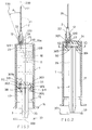
- Figure 1 is an illustration showing the present invention ready for injection use.
- Figure 2 shows coupling of the plunger with the needle when finishing a medical injection.
- Figure 3 shows the retraction of the needle into the syringe of the present invention.
- Figure 4 shows a bent needle in the syringe in accordance with the present invention.
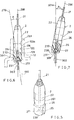
- Figure 5 is an illustration showing the needle of the present invention.
- Figure 6 shows a coupling member coupled with a rear needle portion in accordance with the present invention.
- Figure 7 shows an inclined needle when retracted in the syringe of the present invention.
- Figure 8 is a perspective view of the present invention before being assembled.
- Figure 9 shows an assembly of the present invention.
- Figure 10 is a sectional drawing as viewed from direction 10-10 of Figure 2.
- the present invention comprises: a syringe means 1, a needle device 2, and a plunger means 3.
- the syringe means 1 includes: a syringe cylinder 11 having a hollow hare portion 10 defined in the syringe cylinder 11 for filling liquid medicine 4 in the syringe cylinder 11 and a syringe axis 100 longitudinally existing in a central portion of the syringe cylinder 11, a sleeve portion 12 eccentrically formed on a front side portion of the syringe cylinder 11 contracted forwardly from the cylinder 11 having a central opening 121 formed through the sleeve portion 12, and a diverging port 122 formed in a rear portion of the sleeve portion 12 adjacent to the syringe cylinder 11, a syringe handle 14 formed on a rear end portion of the cylinder 11, a blocking shoulder portion 15a formed at a rear end portion of the sleeve portion 12 and positioned between the central opening 121 of the sleeve portion 12 and the bore portion 10 of the syringe cylinder 11, an annular extension
- the needle device 2 includes: a needle portion 21 having a needle tip 211 formed at a front end of the needle portion 21, a shank portion 22 connected with the needle portion 21, a bifurcated slot 25 longitudinally formed in a rear portion of the shank portion 22 and recessed forwardly from a rear needle end portion 230, a biasing socket 27 generally conical shaped fomed in a rear portion of the shank portion 22 and communicating with a guiding port 231 recessed forwardly from the rear needle end portion 230, and a needle axis 200 longitudinally existing in a central portion of the needle device 2, with the shank portion 22 and the rear needle end portion 230 made of resilient plastic materials; and the shank portion 22 of the needle device 2 having a ratchet-tooth groove 26 annularly recessed in the shank portion 22 to be engaged with the ratchet tooth 120 formed in the sleeve portion 12, and a conical sloping surface 261 circumferentially tapered rearwardly on the shank portion 22 towards the ratchet
- the needle axis 200 is parallel to the syringe axis 100 when the needle device 2 is normally secured on a sleeve portion 12 of the syringe means 1 for injection purpose.
- the biasing socket 27 generally conical shaped includes: a conical bottom 271, a conical apex 272 tapered forwardly from the conical bottom 271, and a longitudinal conical axis 270 aligned with the conical apex 272 to be perpendicular to the conical bottom 271 and to be outwardly inclinedly deviated from the needle axis 200 of the needle device 2 to define an acute angle A between the needle axis 200 and the longitudinal conical axis 270 of the biasing socket 27.
- the conical axis 270 is eccentrically deviated from the syringe axis 100 and interpolatively intersects the syringe axis 100 with the same acute angle A as shown in Figures 1 and 6.
- the biasing socket 27 is snugly engageable with an arrowhead portion 301 of the plunger means 3 for obliquely biasing the needle device 2 when coupled to the plunger means 3 and retracted in the syringe cylinder 11 after finishing an injection.
- the plunger means 3 includes: a plunger 31 slidably held in the syringe cylinder 11 of the syringe means 1, a coupling member 30 retained in a coupling-member recess 34 in the plunger 31 having the arrowhead portion 301 eccentrically formed on a front end of the coupling member 30 operatively insertable in a biasing socket 27 formed in the needle device 2, a holding socket 32 concentrically disposed around the arrowhead portion 301 for operatively coupling a rear needle end pertion 230 when bifurcated by the arrowhead portion 301 inserted into the biasing socket 27, with the rear needle end portion 230 confined within a diverging port 122 formed in a rear portion of a sleeve portion 12 of the syringe means 1, a plunger rod 35 having a plunger handle 37 protruding rearwardly from the plunger 31 for pushing operation of the plunger 31 with the plunger 31 formed with an annular recess 311 in the plunger 31 to be engaged with an
- the coupling member 30 includes: the arrowhead portion 301 being conical shaped and engageable with the biasing socket 27 which is formed as conical shape in the needle device 2 having the arrowhead axis 301a of the arrowhead portion 301 aligned with the needle axis 200 and parallel to the plunger axis 300 and parallel to the syringe axis 100 as shown in Figure 1 ready for a normal medical injection, a neck portion 302 connected with the arrowhead portion 301, a base portion 303 having an annular protrusion 304 circumferentially formed on a periphery of the base portion 303 for well sealable embedding of the base portion 303 in the recess 34 in the plunger 31, and a secant block portion 305 engaged with a secant recess 341 formed at a rear end of the coupling-member recess 34 with the secant block portion 305 secured to a plunger rod 35 of the plunger means 3.
- the plunger handle 37 has a flat bottom edge 371 slidably laid on a flat surface F as shown in Figure 9 for a straight movement of the plunger means 3 in the syringe means 1 for sharply aiming the arrowhead portion 301 at the biasing socket 27 of the needle device 2 as shown in Figures 9, 10 and 2 since the plunger 31 will not be rotated as slidably engageable with the plural longitudinal rail extensions 17 formed in the syringe cylinder 11.
- the secant block portion 305 engaged with the secant recess 341 also enforce such a straight forward movement of the plunger 31 in the cylinder 11.
- the plunger 31 may be pushed forwardly to boost the medicine 4 in the cylinder 11 through the needle device 2 to a patient's body for an intravenous injection by inserting the eccentrically positioned needle device 2 to the patient's blood vessel.
- the arrowhead portion 301 of the coupling member 30 will then be forcibly inserted into the biasing socket 27 of the needle device 2 to squeeze, and expansively bifurcate the rear needle end portion 230 of the needle device 2 to store a resilient potential energy of the bifucated rear needle portion, thereby operatively coupling the coupling member 30 with the needle device 2 as shown in Figures 2, 6.
- the needle tip 211 After re-protruding the needle device 2 outwardly, the needle tip 211 will be retarded against the blocking shoulder portion 15a formed in a front portion of the cylinder 11 ( Figure 4), thereby bending the needle 2 and obstructing its outward protrusion and preventing its injury or contamination to the surroundings.
- the present invention is superior to the earlier invention, U.S. Patent 5,328,475 issued to the same inventor of this application because of the stable engagement of the needle device 2 on the sleeve portion 12 for injection.
- the ratchet tooth 120 in the sleeve portion 12 of the syringe means 1 will retard the ratchet-tooth groove 26 of the shank portion 22 of the needle device 2 to prevent an outward forward ejection of the needle device 2 from the sleeve portion 12 of the syringe means 1; and upon retraction of the needle device 2 as coupled on the plunger 31 into the syringe cylinder 11 after the injection, the conical sloping surface 261 of the shank portion 22 of the needle device 2 will be rearwardly thrusted along the inside conical sloping surface 120a in the sleeve portion 12 for a smooth retraction of the needle device 2 into the syringe cylinder 11 for reliable retraction of the used needle device 2.
- the slope of the conical sloping surfaces 261, 120a has a very small sloping rate.
- the sleeve portion 12 and the needle device 2 are made of plastic material having elastic property for a smooth engagement and disengagement between the sleeve portion 12 and the needle device 2, also for a better packing or sealing to prevent liquid leakage in between the needle device 2 and the sleeve portion 12.
Landscapes
- Health & Medical Sciences (AREA)
- Engineering & Computer Science (AREA)
- Hematology (AREA)
- Anesthesiology (AREA)
- Biomedical Technology (AREA)
- Heart & Thoracic Surgery (AREA)
- Vascular Medicine (AREA)
- Life Sciences & Earth Sciences (AREA)
- Animal Behavior & Ethology (AREA)
- General Health & Medical Sciences (AREA)
- Public Health (AREA)
- Veterinary Medicine (AREA)
- Environmental & Geological Engineering (AREA)
- Infusion, Injection, And Reservoir Apparatuses (AREA)
Priority Applications (1)
| Application Number | Priority Date | Filing Date | Title |
|---|---|---|---|
| EP96305085A EP0818210A1 (de) | 1996-07-10 | 1996-07-10 | Sicherheitsspritze mit einziehbarer selbstvorgespannter Nadel für intravenöse Injektionen ohne Klemmring |
Applications Claiming Priority (1)
| Application Number | Priority Date | Filing Date | Title |
|---|---|---|---|
| EP96305085A EP0818210A1 (de) | 1996-07-10 | 1996-07-10 | Sicherheitsspritze mit einziehbarer selbstvorgespannter Nadel für intravenöse Injektionen ohne Klemmring |
Publications (1)
| Publication Number | Publication Date |
|---|---|
| EP0818210A1 true EP0818210A1 (de) | 1998-01-14 |
Family
ID=8225003
Family Applications (1)
| Application Number | Title | Priority Date | Filing Date |
|---|---|---|---|
| EP96305085A Withdrawn EP0818210A1 (de) | 1996-07-10 | 1996-07-10 | Sicherheitsspritze mit einziehbarer selbstvorgespannter Nadel für intravenöse Injektionen ohne Klemmring |
Country Status (1)
| Country | Link |
|---|---|
| EP (1) | EP0818210A1 (de) |
Cited By (1)
| Publication number | Priority date | Publication date | Assignee | Title |
|---|---|---|---|---|
| DE19825751A1 (de) * | 1998-03-12 | 1999-09-16 | Liu Wen Neng | Sicherheits-Intravenösspritze mit zurückziehbarer Spezialnadel |
Citations (5)
| Publication number | Priority date | Publication date | Assignee | Title |
|---|---|---|---|---|
| DE3339705A1 (de) * | 1983-11-03 | 1985-05-15 | Arzneimittel Gmbh Apotheker Vetter & Co Ravensburg, 7980 Ravensburg | Spritze fuer medizinische zwecke |
| WO1993025257A1 (en) * | 1992-06-15 | 1993-12-23 | Adams Robert D | Needle protected syringe |
| EP0661068A1 (de) * | 1993-12-20 | 1995-07-05 | Long-Hsiung Chen | Vereinfachte Sicherheitsspritze mit zurückziehbarer selbsttätig vorgespannter Nadel für intravenöse Injektion |
| WO1995027524A1 (fr) * | 1994-04-11 | 1995-10-19 | Patrice Elfandi | Seringue a usage unique a aiguille retractable |
| WO1996015820A1 (en) * | 1994-11-22 | 1996-05-30 | Tokita, Hiroshi | Injector |
-
1996
- 1996-07-10 EP EP96305085A patent/EP0818210A1/de not_active Withdrawn
Patent Citations (5)
| Publication number | Priority date | Publication date | Assignee | Title |
|---|---|---|---|---|
| DE3339705A1 (de) * | 1983-11-03 | 1985-05-15 | Arzneimittel Gmbh Apotheker Vetter & Co Ravensburg, 7980 Ravensburg | Spritze fuer medizinische zwecke |
| WO1993025257A1 (en) * | 1992-06-15 | 1993-12-23 | Adams Robert D | Needle protected syringe |
| EP0661068A1 (de) * | 1993-12-20 | 1995-07-05 | Long-Hsiung Chen | Vereinfachte Sicherheitsspritze mit zurückziehbarer selbsttätig vorgespannter Nadel für intravenöse Injektion |
| WO1995027524A1 (fr) * | 1994-04-11 | 1995-10-19 | Patrice Elfandi | Seringue a usage unique a aiguille retractable |
| WO1996015820A1 (en) * | 1994-11-22 | 1996-05-30 | Tokita, Hiroshi | Injector |
Cited By (1)
| Publication number | Priority date | Publication date | Assignee | Title |
|---|---|---|---|---|
| DE19825751A1 (de) * | 1998-03-12 | 1999-09-16 | Liu Wen Neng | Sicherheits-Intravenösspritze mit zurückziehbarer Spezialnadel |
Similar Documents
| Publication | Publication Date | Title |
|---|---|---|
| US5328475A (en) | Simplified safety syringe with retractable self-biased needle | |
| US5405327A (en) | Simplified safety syringe with retractable self-biased needle and minimized plunger | |
| EP0590757B1 (de) | Sichere Einwegspritze mit zurückziehbarer selbstvorgespannter Nadel | |
| US5242402A (en) | Safety syringe with retractible self-biased needle adapted for intravenous injection | |
| AU738073B2 (en) | Retractable needle and syringe combination | |
| US5569203A (en) | Simplified safety syringe with retractable self-biased needle and minimized plunger | |
| US5205826A (en) | Automatically blocked safety syringe | |
| US5431631A (en) | Safety syringe with externally connectable and internally retractable self-biased needle | |
| US5273539A (en) | Automatically blocked safety syringe adapted for intravenous injection | |
| US5562627A (en) | Safety syringe with retractable self-biased needle for intravenous injection without packing ring | |
| US6273870B1 (en) | Retractable needle and syringe combination | |
| US12285253B2 (en) | Blood collection tube holder with single needle | |
| EP0661068B1 (de) | Vereinfachte Sicherheitsspritze mit zurückziehbarer selbsttätig vorgespannter Nadel für intravenöse Injektion | |
| US5295973A (en) | Safety syringe | |
| EP0818210A1 (de) | Sicherheitsspritze mit einziehbarer selbstvorgespannter Nadel für intravenöse Injektionen ohne Klemmring | |
| US20030060758A1 (en) | Safety syringe for ergonomically coupling and inclinedly retracting used needle device into syringe cylinder | |
| KR100312208B1 (ko) | 신축(伸縮)가능한자동경사식바늘을가진,패킹링이없는안전주사기 | |
| EP0818211A1 (de) | Vereinfachte Sicherheitsspritze mit einziehbarer selbstvorgespannter Nadel und mit minimiertem Kolben | |
| CA2242226C (en) | Retractable needle and syringe combination | |
| KR200161888Y1 (ko) | 외부적으로 접속가능하고 내부적으로 철회가능한 자기-경사식 바늘을 가지는 안전 주사기 | |
| JPH0759855A (ja) | 静脈内注射に適した安全注射器 | |
| CZ208296A3 (cs) | Ochranná injekční stříkačka | |
| GB2380680A (en) | Single-use syringe assembly | |
| CZ208196A3 (cs) | Bezpečná injekční stříkačka se zasouvatelnou jehlou, bez těsnicího kroužku |
Legal Events
| Date | Code | Title | Description |
|---|---|---|---|
| PUAI | Public reference made under article 153(3) epc to a published international application that has entered the european phase |
Free format text: ORIGINAL CODE: 0009012 |
|
| AK | Designated contracting states |
Kind code of ref document: A1 Designated state(s): BE CH DE DK ES FR GB GR IT LI NL PT SE |
|
| 17P | Request for examination filed |
Effective date: 19980714 |
|
| AKX | Designation fees paid |
Free format text: BE CH DE DK ES FR GB GR IT LI NL PT SE |
|
| RBV | Designated contracting states (corrected) |
Designated state(s): BE CH DE DK ES FR GB GR IT LI NL PT SE |
|
| STAA | Information on the status of an ep patent application or granted ep patent |
Free format text: STATUS: THE APPLICATION IS DEEMED TO BE WITHDRAWN |
|
| 18D | Application deemed to be withdrawn |
Effective date: 20000201 |