EP0818254A2 - Dispositif de transfert de tÔles dans une installation de presse - Google Patents
Dispositif de transfert de tÔles dans une installation de presse Download PDFInfo
- Publication number
- EP0818254A2 EP0818254A2 EP97111521A EP97111521A EP0818254A2 EP 0818254 A2 EP0818254 A2 EP 0818254A2 EP 97111521 A EP97111521 A EP 97111521A EP 97111521 A EP97111521 A EP 97111521A EP 0818254 A2 EP0818254 A2 EP 0818254A2
- Authority
- EP
- European Patent Office
- Prior art keywords
- gripper
- transfer device
- crossbar
- transfer
- gripper means
- Prior art date
- Legal status (The legal status is an assumption and is not a legal conclusion. Google has not performed a legal analysis and makes no representation as to the accuracy of the status listed.)
- Granted
Links
Images



Classifications
-
- B—PERFORMING OPERATIONS; TRANSPORTING
- B21—MECHANICAL METAL-WORKING WITHOUT ESSENTIALLY REMOVING MATERIAL; PUNCHING METAL
- B21D—WORKING OR PROCESSING OF SHEET METAL OR METAL TUBES, RODS OR PROFILES WITHOUT ESSENTIALLY REMOVING MATERIAL; PUNCHING METAL
- B21D43/00—Feeding, positioning or storing devices combined with, or arranged in, or specially adapted for use in connection with, apparatus for working or processing sheet metal, metal tubes or metal profiles; Associations therewith of cutting devices
- B21D43/02—Advancing work in relation to the stroke of the die or tool
- B21D43/04—Advancing work in relation to the stroke of the die or tool by means in mechanical engagement with the work
- B21D43/05—Advancing work in relation to the stroke of the die or tool by means in mechanical engagement with the work specially adapted for multi-stage presses
-
- B—PERFORMING OPERATIONS; TRANSPORTING
- B21—MECHANICAL METAL-WORKING WITHOUT ESSENTIALLY REMOVING MATERIAL; PUNCHING METAL
- B21D—WORKING OR PROCESSING OF SHEET METAL OR METAL TUBES, RODS OR PROFILES WITHOUT ESSENTIALLY REMOVING MATERIAL; PUNCHING METAL
- B21D43/00—Feeding, positioning or storing devices combined with, or arranged in, or specially adapted for use in connection with, apparatus for working or processing sheet metal, metal tubes or metal profiles; Associations therewith of cutting devices
- B21D43/02—Advancing work in relation to the stroke of the die or tool
- B21D43/04—Advancing work in relation to the stroke of the die or tool by means in mechanical engagement with the work
- B21D43/10—Advancing work in relation to the stroke of the die or tool by means in mechanical engagement with the work by grippers
- B21D43/11—Advancing work in relation to the stroke of the die or tool by means in mechanical engagement with the work by grippers for feeding sheet or strip material
-
- B—PERFORMING OPERATIONS; TRANSPORTING
- B21—MECHANICAL METAL-WORKING WITHOUT ESSENTIALLY REMOVING MATERIAL; PUNCHING METAL
- B21D—WORKING OR PROCESSING OF SHEET METAL OR METAL TUBES, RODS OR PROFILES WITHOUT ESSENTIALLY REMOVING MATERIAL; PUNCHING METAL
- B21D43/00—Feeding, positioning or storing devices combined with, or arranged in, or specially adapted for use in connection with, apparatus for working or processing sheet metal, metal tubes or metal profiles; Associations therewith of cutting devices
- B21D43/02—Advancing work in relation to the stroke of the die or tool
- B21D43/04—Advancing work in relation to the stroke of the die or tool by means in mechanical engagement with the work
- B21D43/14—Advancing work in relation to the stroke of the die or tool by means in mechanical engagement with the work by turning devices, e.g. turn-tables
Definitions
- the invention relates to a transfer device the features of the preamble of claim 1.
- the arranged one behind the other along a parts flow path transfer facilities are provided that the corresponding sheet metal parts from the press stages remove and intermittently from the following press stage respectively.
- clipboards provided on which to be transported Workpieces can be temporarily stored, which allows the width of the transfer step to increase reduce.
- a Used transfer device that the workpieces grabs open tool and in a transfer movement, in which there is a lifting movement of a horizontal Transfer movement overlaid, leads out of the tool or sets in this, with the transfer movement a vertical lowering or depositing movement is superimposed.
- the first processing stage of press systems possibly also a subsequent processing stage, is designed as a drawing stage.
- the further one Processing may require an inclined position of the Sheet metal part in the lower tool. For one, z. E.g. because of the high number of strokes the lifting stroke is not arbitrary be chosen large, on the other hand it is necessary angled, lowered drawing surfaces by deep drawing pass freely above the shape of the lower tool.
- a corresponding conversion device is from the EP-A-0 499 901 has become known.
- To the transfer device include two that extend in the transfer direction, right and left side next to the tools of the press stages arranged guide rails on which carriages are stored.
- the guide rails are with a lifting and Lowering unit connected to a targeted horizontal movement to execute.
- the carriages stand with a transfer drive unit in conjunction to target along the To be able to move rails.
- Between each a crossbeam is arranged on two carriages is rotatably supported on the end of the carriage.
- the cross-beam carries a suction spider that has a number has vacuum feet that can be acted upon by vacuum.
- To the Vacuum spider can be pivoted about a transverse axis the crossbar in question at the end via a coupling connected to a swivel lever, which by means of a the drive cylinder provided pivotable is.
- a transfer device should ideally be designed in this way be a variety of workpieces can handle, so that they can be used for future, in detail unforeseeable tasks can be set up.
- JP 62-142431 is a transfer device known in which a carrier carrying a suction spider is rotatably mounted on a rotating unit.
- the Turning unit is up and down vertically and horizontally movable carrier held.
- crossbars which are rigid in themselves suction spiders rotatably mounted on them.
- the crossmember carries the drive means, e.g. a geared motor, hydraulic or pneumatic Drives that swivel the gripper means as required.
- the end Suspension of the crossbeams is independent of whether the relevant crossbar swiveling gripper means wears or not, uniformly trained. There are not any rotating units acting on the ends of the crossbeams required on the load-bearing and guiding means, e.g.
- Carriages mounted on running rails, to be provided firmly would be. This enables the quick change of crossbeams with rotatable gripper means against cross beams with non-swiveling gripper means and vice versa. Of the constructive structural and economic effort thus for each application to the required Dimension reduced. At the same time, the transfer facility offers a high degree of variability and enables one quick and easy adaptation to different, also future transfer tasks.
- the swiveling storage of the gripper means on the Crossbeam and the assignment of one of the crossbeam creates carried drive means to each gripper means the basis for that on the same crossbar provided gripper means in different controlling or pivoting gripper units divided becomes.
- a first and a second suction spider can be provided, one of which only one is pivoted or the different be pivoted.
- This can be different pivoting sheet metal parts that are juxtaposed by the Press stages to be transported are handled. Such may be necessary if from a circuit board two separate sheet metal parts are created that are different are designed.
- the versatility of the invention Transfer device even enables a sheet metal part that as a cutout for training a large one Opening in another sheet metal part separated from this has been transported with it synchronously and to shape it in its own part. It can be done with its own suction spider on the same cross-beam sits like the suction spider for the surrounding, larger part, kept and transported and also in other tilt angles are transferred.
- a coupling arrangement between the crossbar and the gripper means or one of gripper means, Bearing device and drive means formed gripper unit can, if necessary, loosen the gripper unit of the crossbars so that the crossbars can be converted for a particular application.
- the axis of rotation of the gripper means is preferably within the crossbar, with the focus of the Workpiece lies below the crossbar. Thereby no noteworthy arises on the drive means acting torque by the weight of the Workpiece.
- Design belongs to the storage facility at least one split bearing unit, the two arcuate guide surfaces has on which the gripper means by Rollers are stored, being for coupling with a as Gear motor serving drive means a gear segment serves that can also be understood as a curved rack can.
- This design enables a particularly small one Height of the swiveling gripper unit, which is not or is hardly larger than that of an immovable. Thereby becomes the permissible vertical stroke of the transfer device not limited.
- FIG. 1 shows a press system 1, which has a series of press stations, of which two press stations 3, 4 are illustrated.
- Press station 3 4 includes a sliding table 5, 6 Inclusion of a lower tool 7, 8, each an upper tool 9, 10 held on a tappet is assigned is.
- the upper tools 9, 10 are of the Tappets in the direction of arrows 11, 12 moved up and down in cycles.
- sheet metal parts 14, 15 are processed in stages.
- a further sheet metal part 16 between the press stations 3, 4 can be halfway there a clipboard between the two sliding tables 5, 6 18 may be arranged. If necessary, this has several Axes adjustable stencils around the sheet metal part when filing and if necessary for the Align further transport in height and inclined position.
- the sheet metal parts 14, 15, 16 are along a Transfer curve 21, 22 from the press station 3 to the Clipboard 18 and from this to the press station 4 transported or directly from press station 3 to press station 4 transported.
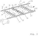
- the transfer curves 21, 22 are achieved by vertical lifting-lowering movements (V in Fig. 2) formed, which a horizontal transport stroke (H in Fig. 2) is superimposed. It may be necessary that the sheet metal part 14, 15 or 16 already in the lifting movement from the lower tool 7, 8 or when removing from the Clipboard 18 is to be turned into such a tilted position, that deep-drawn edges are not separated from the respective lower tool 7, 8 or the inclusion of the Clipboard 18 are hindered.
- a transfer device serves to pivot the same 23, a partial section of which is shown in FIG outermost is shown schematically. Belong to this two parallel to each other and parallel to each other a transport direction T arranged walking beam or Running rails 24, 25, on which carriages 26, 27, 28, 29, 30, 31 movably supported in the transport direction T. are, each of which is only indicated schematically Linkage 32 are driven. Each in pairs between two carriages 26, 27; 28, 29; 30, 31 is a crossbar 33, 34, 35 held with their ends releasably the respective carriage 26, 27, 28, 29, 30, 31 connected is. Coupling means such as those used, for example, emerge from Fig. 3.
- Each crossbar 33, 34, 35 carries as a gripper means for sheet metal parts 14, 15, 16 suction spiders 36, 37, 38, at least those held on the cross-beam 34 Suction spiders 37 rotatably mounted on the crossbar 34 are.
- the crossbar 34 a continuous, rigid, from a box profile trained carrier on with at both ends Coupling halves 41, 42 for connection to the carriage 28, 29 is provided.
- the carrier carries two suction units 37a, 37b, which are mirror-symmetrical to one another are. The following, referring to the suction unit 37a relevant description applies accordingly to the Suction unit 37b.
- the suction unit 37a includes a number of arms 44a suction device 46a connected to a frame 45a.
- the Frame 45a is, for example, from FIGS. 4 and 5 apparent bearing device 47a on a bracket 48a mounted on the corresponding, from the crossbar 34th supported bases 49a spaced from each other, 50a can be coupled.
- the bracket 48a includes the crossbar 34, such as Fig. 5 shows three sides and is open at the bottom. Same thing applies to the part connected to the base 50a 48a 'of the bracket.
- bracket 48a, 48a are as coupling counterparts serving, spade-shaped extensions as an insertion aid trained and coupling bolts available by the Sockets 49a, 50a are included and with these one Form releasable clutch assembly. Security means prevent unintentional loosening of the coupling arrangement.
- the bearing device 47a is on the holder 48a, 48a 'formed arcuate surfaces 52a, 53a formed, each in pairs on a common Circle lie whose center M is the center of the Crossbar 34 corresponds (Fig. 5). That down likewise open frame 45a is, for example, by total four rollers 56a, 57a, 58a, 59a on the arcuate Surfaces 52a, 53a stored. As an alternative to this Roller bearings would also be, for example, an arcuate profile rail guide conceivable.
- a connected to the frame 45a, next to the side Gear segment 61a arranged on the rollers 58a, 59a is used for coupling the frame 45a to a servo motor 62a, the next to the bracket 48a at the same height as that Crossbar 34 is arranged.
- the servo motor 62a is via a high-reduction, so-called harmonic drive gear 63a with a toothing at the end Lever 64 connected, which is also a gear segment can be understood and its interlocking with the Gear segment 61a meshes. His axis of rotation is there aligned parallel to the axis of rotation of the frame 45a.
- the press system 1 described so far and in particular the transfer device 23 operate as follows:
- press stations 3, 4 are illustrated by means of corresponding drive units A the rails 24, 25 in the vertical direction V and the carriages 26, 27, 28, 29, 30, 31 moved in the horizontal direction H so that the Cross members 33, 34, 35 pass through the transfer curves 21, 22.
- the one in the return stroke in different positions shown cross members 34, 35 can be so controlled that the suction spiders 37 (37a, 37b) during the horizontal and / or vertical movement of the Swivel crossbar 34 around this.
- the suction spiders 37 can be positioned in an inclined position in the them to that held by the clipboard 18 in a tilted position Sheet metal part 16 are attachable. With the reset movement at the cross member 34, the suction spiders 37 in rotated this position. So that the sheet metal part 16 the transfer curve 22 into the lower tool 8 without interference placed. Even when inserting the sheet metal part 16 in the Press station 4 or when removing from press station 3 can if necessary by pivoting the suction spiders 37 be brought into different tilt positions.
- each one or carry multiple swivel unit (s) are diverse Combinations possible.
- the swivel units can also non-swiveling suction spiders on the bases 49, 50 be coupled in the horizontal direction or are oriented in an inclined direction.
- base 49a, 50a form with corresponding extensions of the holder 48a, 48a ' Coupling arrangement with a not shown Provide locking device for locking is.
- the relevant clutch arrangement is unlocked due to a short stroke, axially to the crossbar 34 directed movement and pivoting away of the locking bolt, after which the suction unit 37a, 37b is removable. If necessary, the clutch arrangement also be replaced by other lanyards, so that the relevant suction unit 37a, 37a with the respective crossbar 34 (33, 35) is connected.
- a transfer device 23 for a press system 1 has cross members 33, 34, 35, on each of which at least one suction unit 37a is held around the crossbar 34 is pivotally mounted on this.
- the suction unit 37a preferably has an electrical one Drive on, by means of which the swivel movement the transfer curve to be traversed (horizontal and Vertical movement) is tunable. If necessary, can a crossbar two or more suction units 37a, 37b are arranged, which can be pivoted independently of one another are. Retrofitting and retrofitting of existing ones Crossbeam is used by replacement of previously non-swiveling suction units by swiveling possible. Other changes to the mechanical Structure of the transfer device 23 are not required.
Landscapes
- Engineering & Computer Science (AREA)
- Mechanical Engineering (AREA)
- Specific Conveyance Elements (AREA)
- Press Drives And Press Lines (AREA)
- Sheets, Magazines, And Separation Thereof (AREA)
- Folding Of Thin Sheet-Like Materials, Special Discharging Devices, And Others (AREA)
Applications Claiming Priority (2)
| Application Number | Priority Date | Filing Date | Title |
|---|---|---|---|
| DE19628333A DE19628333A1 (de) | 1996-07-13 | 1996-07-13 | Umsetzeinrichtung für Blechteile in einer Pressenanlage |
| DE19628333 | 1996-07-13 |
Publications (3)
| Publication Number | Publication Date |
|---|---|
| EP0818254A2 true EP0818254A2 (fr) | 1998-01-14 |
| EP0818254A3 EP0818254A3 (fr) | 1998-04-01 |
| EP0818254B1 EP0818254B1 (fr) | 2000-04-05 |
Family
ID=7799772
Family Applications (1)
| Application Number | Title | Priority Date | Filing Date |
|---|---|---|---|
| EP97111521A Expired - Lifetime EP0818254B1 (fr) | 1996-07-13 | 1997-07-08 | Dispositif de transfert de tôles dans une installation de presse |
Country Status (7)
| Country | Link |
|---|---|
| US (1) | US5993143A (fr) |
| EP (1) | EP0818254B1 (fr) |
| KR (1) | KR980008384A (fr) |
| CN (1) | CN1080150C (fr) |
| CZ (1) | CZ288005B6 (fr) |
| DE (2) | DE19628333A1 (fr) |
| ES (1) | ES2144814T3 (fr) |
Cited By (7)
| Publication number | Priority date | Publication date | Assignee | Title |
|---|---|---|---|---|
| EP0901848A1 (fr) * | 1997-09-13 | 1999-03-17 | SCHULER PRESSEN GmbH & Co. | Presse de transfert avec changement d' outil automatique |
| EP0972586A2 (fr) | 1998-07-15 | 2000-01-19 | Müller Weingarten AG | Procédé pour la commande d' actionnement d'une presse de transfert pour grandes pièces et dispositif pour réaliser ce procédé |
| CN102601251A (zh) * | 2012-03-08 | 2012-07-25 | 安徽江淮汽车股份有限公司 | 用于冲压自动化线的板料定位对中台装置 |
| WO2012136750A1 (fr) * | 2011-04-08 | 2012-10-11 | Schuler Pressen Gmbh | Dispositif de transfert pour une presse ou un train de presses comprenant une transmission et support de base échangeable |
| EP2664395A3 (fr) * | 2012-05-15 | 2016-08-03 | Aida Engineering, Ltd. | Appareil de transfert de pièce |
| CN108357182A (zh) * | 2018-04-08 | 2018-08-03 | 东莞市沃德精密机械有限公司 | 阻尼片全自动贴装机 |
| EP3479921A1 (fr) * | 2017-11-07 | 2019-05-08 | ABB Schweiz AG | Dispositif de manipulation de pièces |
Families Citing this family (16)
| Publication number | Priority date | Publication date | Assignee | Title |
|---|---|---|---|---|
| DE19851746A1 (de) * | 1998-11-10 | 2000-05-11 | Schuler Pressen Gmbh & Co | Modularer Transfer mit Schwenk- und Linearantrieben |
| DE19851744A1 (de) * | 1998-11-10 | 2000-05-11 | Schuler Pressen Gmbh & Co | Transport- und Positioniereinrichtung |
| DE19851743A1 (de) * | 1998-11-10 | 2000-05-11 | Schuler Pressen Gmbh & Co | Positioniereinrichtung mit Gewichtsausgleich |
| DE10064155A1 (de) * | 2000-12-22 | 2002-07-11 | Schuler Pressen Gmbh & Co | Bearbeitungsvorrichtung |
| US6592351B2 (en) | 2001-01-22 | 2003-07-15 | Crane Plastics Company Llc | Turret loading device for extrusion line |
| DE102005009734B4 (de) * | 2004-03-19 | 2016-10-13 | Trumpf Werkzeugmaschinen Gmbh + Co. Kg | Maschinelle Handhabungsvorrichtung, Saugeranordnung hierfür sowie Saugereinheiten einer Saugeranordnung |
| DE102004018059B4 (de) * | 2004-04-08 | 2008-01-24 | Schuler Pressen Gmbh & Co. Kg | Transfereinrichtung und Transferverfahren |
| EP1990110A1 (fr) * | 2007-05-08 | 2008-11-12 | Güdel Group Ag | Dispositif de centrage pour pièces plates dans une presse et procédé d'établissement d'un tel dispositif de centrage |
| WO2010099409A1 (fr) * | 2009-02-27 | 2010-09-02 | Titanium Metals Corporations | Systèmes et procédés de profilage de produits formant feuille |
| JP2011194428A (ja) * | 2010-03-18 | 2011-10-06 | Aida Engineering Ltd | 搬送装置の破損防止機構およびそれを用いた搬送装置 |
| JP6081602B2 (ja) * | 2012-10-16 | 2017-02-15 | エービービー テクノロジー アーゲー | プレスラインで被加工物を扱うためのシステム |
| DE102012110065A1 (de) | 2012-10-22 | 2014-04-24 | Schuler Automation Gmbh & Co. Kg | Umformanlage |
| DE102014117026B3 (de) * | 2014-11-20 | 2015-12-03 | Strothmann Machines & Handling GmbH | Transfervorrichtung |
| JP6185104B1 (ja) * | 2016-03-14 | 2017-08-23 | アイダエンジニアリング株式会社 | プレス機械のワーク搬送装置 |
| CN114045712B (zh) * | 2021-11-03 | 2024-06-14 | 武汉利德测控技术有限公司 | 一种拨钢轨装置 |
| CN116765250B (zh) * | 2023-06-12 | 2026-02-13 | 福安市神威电机有限公司 | 一种电机罩自动化生产装置及其方法 |
Family Cites Families (4)
| Publication number | Priority date | Publication date | Assignee | Title |
|---|---|---|---|---|
| JPS62142431A (ja) * | 1985-12-17 | 1987-06-25 | Matsushita Electric Ind Co Ltd | 通信装置 |
| US4921387A (en) * | 1988-09-16 | 1990-05-01 | The Budd Company | Combination transfer/turnover machine |
| WO1991019577A1 (fr) * | 1990-06-15 | 1991-12-26 | Komatsu Ltd. | Alimentateur transporteur |
| DE4104810A1 (de) * | 1991-02-16 | 1992-08-20 | Schuler Gmbh L | Einrichtung zum umsetzen von blechteilen in einer pressenanlage |
-
1996
- 1996-07-13 DE DE19628333A patent/DE19628333A1/de not_active Withdrawn
-
1997
- 1997-07-08 DE DE59701392T patent/DE59701392D1/de not_active Expired - Fee Related
- 1997-07-08 ES ES97111521T patent/ES2144814T3/es not_active Expired - Lifetime
- 1997-07-08 EP EP97111521A patent/EP0818254B1/fr not_active Expired - Lifetime
- 1997-07-09 US US08/891,873 patent/US5993143A/en not_active Expired - Fee Related
- 1997-07-10 CZ CZ19972193A patent/CZ288005B6/cs not_active IP Right Cessation
- 1997-07-14 CN CN97114572A patent/CN1080150C/zh not_active Expired - Fee Related
- 1997-07-14 KR KR1019970032569A patent/KR980008384A/ko not_active Ceased
Cited By (12)
| Publication number | Priority date | Publication date | Assignee | Title |
|---|---|---|---|---|
| EP0901848A1 (fr) * | 1997-09-13 | 1999-03-17 | SCHULER PRESSEN GmbH & Co. | Presse de transfert avec changement d' outil automatique |
| US6126582A (en) * | 1997-09-13 | 2000-10-03 | Schuler Pressen Gmbh & Co. | Transfer presses with an automatic tooling change |
| EP0972586A2 (fr) | 1998-07-15 | 2000-01-19 | Müller Weingarten AG | Procédé pour la commande d' actionnement d'une presse de transfert pour grandes pièces et dispositif pour réaliser ce procédé |
| WO2012136750A1 (fr) * | 2011-04-08 | 2012-10-11 | Schuler Pressen Gmbh | Dispositif de transfert pour une presse ou un train de presses comprenant une transmission et support de base échangeable |
| DE102011001924B4 (de) * | 2011-04-08 | 2013-09-19 | Schuler Pressen Gmbh | Transfereinrichtung für eine Presse oder Pressenstraße mit Achsantrieb und auswechselbarem Grundträger |
| US9713835B2 (en) | 2011-04-08 | 2017-07-25 | Schuler Pressen Gmbh | Transfer arrangement for a press or press line with an axial drive and interchangeable base |
| CN102601251A (zh) * | 2012-03-08 | 2012-07-25 | 安徽江淮汽车股份有限公司 | 用于冲压自动化线的板料定位对中台装置 |
| CN102601251B (zh) * | 2012-03-08 | 2014-04-02 | 安徽江淮汽车股份有限公司 | 用于冲压自动化线的板料定位对中台装置 |
| EP2664395A3 (fr) * | 2012-05-15 | 2016-08-03 | Aida Engineering, Ltd. | Appareil de transfert de pièce |
| EP3479921A1 (fr) * | 2017-11-07 | 2019-05-08 | ABB Schweiz AG | Dispositif de manipulation de pièces |
| CN108357182A (zh) * | 2018-04-08 | 2018-08-03 | 东莞市沃德精密机械有限公司 | 阻尼片全自动贴装机 |
| CN108357182B (zh) * | 2018-04-08 | 2023-09-08 | 东莞市沃德精密机械有限公司 | 阻尼片全自动贴装机 |
Also Published As
| Publication number | Publication date |
|---|---|
| CZ219397A3 (cs) | 1999-04-14 |
| ES2144814T3 (es) | 2000-06-16 |
| CN1171989A (zh) | 1998-02-04 |
| EP0818254B1 (fr) | 2000-04-05 |
| CN1080150C (zh) | 2002-03-06 |
| EP0818254A3 (fr) | 1998-04-01 |
| US5993143A (en) | 1999-11-30 |
| DE19628333A1 (de) | 1998-01-15 |
| CZ288005B6 (cs) | 2001-03-14 |
| KR980008384A (ko) | 1998-04-30 |
| DE59701392D1 (de) | 2000-05-11 |
Similar Documents
| Publication | Publication Date | Title |
|---|---|---|
| EP0818254B1 (fr) | Dispositif de transfert de tôles dans une installation de presse | |
| EP0672480B1 (fr) | Système de transport | |
| EP1313575B1 (fr) | Systeme de transport a bras articule | |
| EP0671228B1 (fr) | Installation de transport pour pièces à usiner dans une presse | |
| DE3629069A1 (de) | Palettenzufuhreinrichtung fuer mindestens eine werkzeugmaschine | |
| EP2506995A1 (fr) | Dispositif de transport | |
| EP2821187B1 (fr) | Dispositif et procédé de traitement | |
| EP0850710B1 (fr) | Transfert multiaxial flexible | |
| DE4104810A1 (de) | Einrichtung zum umsetzen von blechteilen in einer pressenanlage | |
| EP0901848B1 (fr) | Presse de transfert avec changement d' outil automatique | |
| EP0621093B1 (fr) | Train de presses avec dispositif de transfert pour transférer des pièces | |
| EP1123761B1 (fr) | Système de transport horizontal | |
| DE10352982A1 (de) | Gelenkarmtransportvorrichtung | |
| DE102004051977B4 (de) | Vorrichtung zum Transport und zur Lageveränderung von Werkstücken | |
| EP4321273B1 (fr) | Manipulateur de pièces à usiner | |
| EP0507098B1 (fr) | Dispositif de transport d'une presse transfert pour transporter des pièces de grande taille | |
| EP0878251B1 (fr) | Presse-transfer avec un support latéral sur une table mobile pour les porte-pièce | |
| EP0271008B1 (fr) | Disposition de transport pour le transport de carrosseries de véhicule à moteur | |
| EP2907762A1 (fr) | Chariot porte-outil pour machines d'emballage | |
| DE4320430C2 (de) | Transferpressenkomplex | |
| DE102004052001B4 (de) | Automatische Toolingwechselvorrichtung | |
| DE3239482C2 (fr) | ||
| EP0847818B1 (fr) | Presse de transfert | |
| EP1563926B1 (fr) | Dispositif et procédé de transport de pièces à usiner | |
| DE10112393B4 (de) | Vorrichtung zum Transport von Formteilen |
Legal Events
| Date | Code | Title | Description |
|---|---|---|---|
| PUAI | Public reference made under article 153(3) epc to a published international application that has entered the european phase |
Free format text: ORIGINAL CODE: 0009012 |
|
| AK | Designated contracting states |
Kind code of ref document: A2 Designated state(s): DE ES FR GB IT SE |
|
| PUAL | Search report despatched |
Free format text: ORIGINAL CODE: 0009013 |
|
| AK | Designated contracting states |
Kind code of ref document: A3 Designated state(s): AT BE CH DE DK ES FI FR GB GR IE IT LI LU MC NL PT SE |
|
| 17P | Request for examination filed |
Effective date: 19980918 |
|
| AKX | Designation fees paid |
Free format text: DE ES FR GB IT SE |
|
| RBV | Designated contracting states (corrected) |
Designated state(s): DE ES FR GB IT SE |
|
| GRAG | Despatch of communication of intention to grant |
Free format text: ORIGINAL CODE: EPIDOS AGRA |
|
| GRAG | Despatch of communication of intention to grant |
Free format text: ORIGINAL CODE: EPIDOS AGRA |
|
| GRAH | Despatch of communication of intention to grant a patent |
Free format text: ORIGINAL CODE: EPIDOS IGRA |
|
| 17Q | First examination report despatched |
Effective date: 19990818 |
|
| RAP1 | Party data changed (applicant data changed or rights of an application transferred) |
Owner name: SCHULER PRESSEN GMBH & CO. KG |
|
| GRAH | Despatch of communication of intention to grant a patent |
Free format text: ORIGINAL CODE: EPIDOS IGRA |
|
| GRAA | (expected) grant |
Free format text: ORIGINAL CODE: 0009210 |
|
| AK | Designated contracting states |
Kind code of ref document: B1 Designated state(s): DE ES FR GB IT SE |
|
| GBT | Gb: translation of ep patent filed (gb section 77(6)(a)/1977) |
Effective date: 20000418 |
|
| REF | Corresponds to: |
Ref document number: 59701392 Country of ref document: DE Date of ref document: 20000511 |
|
| REG | Reference to a national code |
Ref country code: ES Ref legal event code: FG2A Ref document number: 2144814 Country of ref document: ES Kind code of ref document: T3 |
|
| ITF | It: translation for a ep patent filed | ||
| ET | Fr: translation filed | ||
| PLBE | No opposition filed within time limit |
Free format text: ORIGINAL CODE: 0009261 |
|
| STAA | Information on the status of an ep patent application or granted ep patent |
Free format text: STATUS: NO OPPOSITION FILED WITHIN TIME LIMIT |
|
| 26N | No opposition filed | ||
| REG | Reference to a national code |
Ref country code: GB Ref legal event code: IF02 |
|
| PGFP | Annual fee paid to national office [announced via postgrant information from national office to epo] |
Ref country code: GB Payment date: 20020626 Year of fee payment: 6 |
|
| PGFP | Annual fee paid to national office [announced via postgrant information from national office to epo] |
Ref country code: FR Payment date: 20020723 Year of fee payment: 6 |
|
| PGFP | Annual fee paid to national office [announced via postgrant information from national office to epo] |
Ref country code: ES Payment date: 20020725 Year of fee payment: 6 |
|
| PGFP | Annual fee paid to national office [announced via postgrant information from national office to epo] |
Ref country code: SE Payment date: 20020726 Year of fee payment: 6 |
|
| PG25 | Lapsed in a contracting state [announced via postgrant information from national office to epo] |
Ref country code: GB Free format text: LAPSE BECAUSE OF NON-PAYMENT OF DUE FEES Effective date: 20030708 |
|
| PG25 | Lapsed in a contracting state [announced via postgrant information from national office to epo] |
Ref country code: SE Free format text: LAPSE BECAUSE OF NON-PAYMENT OF DUE FEES Effective date: 20030709 Ref country code: ES Free format text: LAPSE BECAUSE OF NON-PAYMENT OF DUE FEES Effective date: 20030709 |
|
| PGFP | Annual fee paid to national office [announced via postgrant information from national office to epo] |
Ref country code: DE Payment date: 20030912 Year of fee payment: 7 |
|
| GBPC | Gb: european patent ceased through non-payment of renewal fee |
Effective date: 20030708 |
|
| EUG | Se: european patent has lapsed | ||
| PG25 | Lapsed in a contracting state [announced via postgrant information from national office to epo] |
Ref country code: FR Free format text: LAPSE BECAUSE OF NON-PAYMENT OF DUE FEES Effective date: 20040331 |
|
| REG | Reference to a national code |
Ref country code: FR Ref legal event code: ST |
|
| REG | Reference to a national code |
Ref country code: ES Ref legal event code: FD2A Effective date: 20030709 |
|
| PG25 | Lapsed in a contracting state [announced via postgrant information from national office to epo] |
Ref country code: DE Free format text: LAPSE BECAUSE OF NON-PAYMENT OF DUE FEES Effective date: 20050201 |
|
| PG25 | Lapsed in a contracting state [announced via postgrant information from national office to epo] |
Ref country code: IT Free format text: LAPSE BECAUSE OF NON-PAYMENT OF DUE FEES;WARNING: LAPSES OF ITALIAN PATENTS WITH EFFECTIVE DATE BEFORE 2007 MAY HAVE OCCURRED AT ANY TIME BEFORE 2007. THE CORRECT EFFECTIVE DATE MAY BE DIFFERENT FROM THE ONE RECORDED. Effective date: 20050708 |