EP0818333A2 - Wärmepumpe des Gaseinspritztyps - Google Patents
Wärmepumpe des Gaseinspritztyps Download PDFInfo
- Publication number
- EP0818333A2 EP0818333A2 EP97111314A EP97111314A EP0818333A2 EP 0818333 A2 EP0818333 A2 EP 0818333A2 EP 97111314 A EP97111314 A EP 97111314A EP 97111314 A EP97111314 A EP 97111314A EP 0818333 A2 EP0818333 A2 EP 0818333A2
- Authority
- EP
- European Patent Office
- Prior art keywords
- air
- amount
- heat exchanger
- refrigerant
- gas injection
- Prior art date
- Legal status (The legal status is an assumption and is not a legal conclusion. Google has not performed a legal analysis and makes no representation as to the accuracy of the status listed.)
- Granted
Links
Images


Classifications
-
- F—MECHANICAL ENGINEERING; LIGHTING; HEATING; WEAPONS; BLASTING
- F25—REFRIGERATION OR COOLING; COMBINED HEATING AND REFRIGERATION SYSTEMS; HEAT PUMP SYSTEMS; MANUFACTURE OR STORAGE OF ICE; LIQUEFACTION SOLIDIFICATION OF GASES
- F25B—REFRIGERATION MACHINES, PLANTS OR SYSTEMS; COMBINED HEATING AND REFRIGERATION SYSTEMS; HEAT PUMP SYSTEMS
- F25B49/00—Arrangement or mounting of control or safety devices
- F25B49/02—Arrangement or mounting of control or safety devices for compression type machines, plants or systems
- F25B49/027—Condenser control arrangements
-
- B—PERFORMING OPERATIONS; TRANSPORTING
- B60—VEHICLES IN GENERAL
- B60H—ARRANGEMENTS OF HEATING, COOLING, VENTILATING OR OTHER AIR-TREATING DEVICES SPECIALLY ADAPTED FOR PASSENGER OR GOODS SPACES OF VEHICLES
- B60H1/00—Heating, cooling or ventilating devices
- B60H1/00642—Control systems or circuits; Control members or indication devices for heating, cooling or ventilating devices
- B60H1/00814—Control systems or circuits characterised by their output, for controlling particular components of the heating, cooling or ventilating installation
- B60H1/00878—Control systems or circuits characterised by their output, for controlling particular components of the heating, cooling or ventilating installation the components being temperature regulating devices
- B60H1/00899—Controlling the flow of liquid in a heat pump system
- B60H1/00907—Controlling the flow of liquid in a heat pump system where the flow direction of the refrigerant changes and an evaporator becomes condenser
-
- B—PERFORMING OPERATIONS; TRANSPORTING
- B60—VEHICLES IN GENERAL
- B60H—ARRANGEMENTS OF HEATING, COOLING, VENTILATING OR OTHER AIR-TREATING DEVICES SPECIALLY ADAPTED FOR PASSENGER OR GOODS SPACES OF VEHICLES
- B60H1/00—Heating, cooling or ventilating devices
- B60H1/00642—Control systems or circuits; Control members or indication devices for heating, cooling or ventilating devices
- B60H1/00814—Control systems or circuits characterised by their output, for controlling particular components of the heating, cooling or ventilating installation
- B60H1/00878—Control systems or circuits characterised by their output, for controlling particular components of the heating, cooling or ventilating installation the components being temperature regulating devices
- B60H2001/00935—Control systems or circuits characterised by their output, for controlling particular components of the heating, cooling or ventilating installation the components being temperature regulating devices comprising four way valves for controlling the fluid direction
-
- F—MECHANICAL ENGINEERING; LIGHTING; HEATING; WEAPONS; BLASTING
- F25—REFRIGERATION OR COOLING; COMBINED HEATING AND REFRIGERATION SYSTEMS; HEAT PUMP SYSTEMS; MANUFACTURE OR STORAGE OF ICE; LIQUEFACTION SOLIDIFICATION OF GASES
- F25B—REFRIGERATION MACHINES, PLANTS OR SYSTEMS; COMBINED HEATING AND REFRIGERATION SYSTEMS; HEAT PUMP SYSTEMS
- F25B2400/00—Component parts or details not otherwise provided for in this subclass
- F25B2400/13—Economisers
-
- F—MECHANICAL ENGINEERING; LIGHTING; HEATING; WEAPONS; BLASTING
- F25—REFRIGERATION OR COOLING; COMBINED HEATING AND REFRIGERATION SYSTEMS; HEAT PUMP SYSTEMS; MANUFACTURE OR STORAGE OF ICE; LIQUEFACTION SOLIDIFICATION OF GASES
- F25B—REFRIGERATION MACHINES, PLANTS OR SYSTEMS; COMBINED HEATING AND REFRIGERATION SYSTEMS; HEAT PUMP SYSTEMS
- F25B2400/00—Component parts or details not otherwise provided for in this subclass
- F25B2400/23—Separators
Definitions
- the present invention relates to a gas injection type heat pump to improve a heating capacity thereof.
- the present invention is suitably employed in an air conditioning apparatus for a vehicle, and especially in a heat pump system for air-conditioning, for an electric vehicle used in cold district.
- the Applicant has proposed in the European Patent Application No. 96112271.0 that, in a gas injection type heat pump, an electric type expansion valve as decompressing means at the high-pressure side is disposed at an upstream side of a gas-liquid separator at an intermediate pressure, a throttling amount of the electric expansion valve is controlled to increase the intermediate pressure of the gas-liquid separator, and an amount of the gas injected into a compressor is increased so that the heating capacity is improved.
- the inventors have variously studied and examined the above-described apparatus and found out that the following problem occurs.
- FIG. 9 shows a Mollier diagram in the gas injection type heat pump.
- the chain line shows a case where the amount of air passing through the inside heat exchanger is large (the air amount is 350 m 3 /h), and the solid line shows a case where the amount of air passing through the inside heat exchanger is small (the air amount is 180 m 3 /h).
- the gas injection amount may be greatly reduced as compared with when the amount of air passing through the inside heat exchanger is small.
- the present invention has an object to improve the heating capacity by increasing the gas injection amount in the gas injection type heat pump apparatus.
- a physical amount relative to high-pressure side pressure is detected in a heating operation, and an upper limit value of an amount of air passing through an inside heat exchanger is determined based on the detection value.
- the upper limit value and a set air amount set by air amount setting means are compared.
- the set air amount is larger than the upper limit value, the amount of the air passing through the inside heat exchanger is restricted within the upper limit value.
- the high-pressure side pressure increases, and an intermediate pressure in a gas-liquid separator also increases. Therefore, the gas injection amount can be increased, and a heating capacity can be effectively improved.
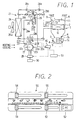
- FIGS. 1 to 6 A first embodiment in which the present invention is employed in an air conditioning apparatus for an electric vehicle will be described with reference to FIGS. 1 to 6. Firstly, an entire construction of the embodiment will be described.
- An air conditioning unit 1 is disposed in a passenger compartment of an electric vehicle, and an air conditioning duct 2 thereof constructs an air passage for introducing conditioned air into the passenger compartment.
- an air conditioning duct 2 At one end side of the air conditioning duct 2, there are provided suction inlets 3 and 4 for sucking inside air and outside air, respectively.
- the inside air suction inlet 3 and the outside air suction inlet 4 are selectively opened and closed by an inside air/outside air switching door 5, and the inside air/outside air switching door 5 is actuated by a servomotor (not shown).
- a blower 6 for generating an air flow is disposed adjacent to the suction inlets 3 and 4.
- the blower 6 includes a fan motor 7a and a centrifugal fan 7b actuated by the fan motor 7a.
- a foot air outlet 8 for blowing conditioned air toward feet of a passenger in the passenger compartment
- a face air outlet 9 for blowing conditioned air toward an upper half body of the passenger in the passenger compartment
- a defroster air outlet 10 for blowing conditioned air toward an inner surface of a windshield of the vehicle.
- Air passages of these air outlets 8 - 10 are opened or closed by doors 11 - 13, respectively, and each of doors 11 - 13 is actuated by a servomotor (not shown).
- the inside heat exchanger 14 constructs a part of a refrigeration cycle 21 described later, and functions as a condenser in a heating operation mode, which radiates condensation latent heat of the refrigerant to heat air in the duct 2.
- the inside heat exchanger functions as an evaporator, which absorbs evaporation latent heat of the refrigerant from air in the air conditioning duct 2 to dehumidify and cool the air.
- the refrigeration cycle 21 is constructed as the gas injection type heat pump in which the heating and cooling operation for the passenger compartment is performed by the inside heat exchanger 14 and includes the following components in addition to the inside heat exchanger 14. That is, the refrigeration cycle 21 further includes a compressor 22 for sucking, compressing and discharging the refrigerant, an electromagnetic four way valve 23 for switching a flow of the refrigerant, an outside heat exchanger 24, a gas-liquid separator 25, a fixed throttle (first decompressing means) 26 for decompressing high pressure side refrigerant to an intermediate pressure (e.g., approximately 4 - 13 kg/cm 2 ), a temperature responding type expansion valve (second decompressing means) 27, and check valves 28a - 28e.
- a compressor 22 for sucking, compressing and discharging the refrigerant
- an electromagnetic four way valve 23 for switching a flow of the refrigerant
- an outside heat exchanger 24 for switching a flow of the refrigerant
- a gas-liquid separator 25 for decom
- the above-described compressor 22 is of an electric type and is actuated by an electric motor (not shown) to suck, compress, and discharge the refrigerant.
- the electric motor is disposed integrally with the compressor 22 in a sealed case, and an electric power supplied to the electric motor is controlled by the an inverter 29 so that a rotational speed of the compressor 22 is continuously changed.
- the inverter 29 is connected to a battery mounted on the vehicle 30, and an electric current supplied to the inverter 29 is controlled by a control unit 40.
- the above-described compressor 22 is provided with a discharge port 22a for discharging the compressed refrigerant, a suction port 22b for sucking the low-pressure side refrigerant in the cycle, and a gas injection port 22c through which gas refrigerant having an intermediate pressure, which is separated in the gas-liquid separator 25, is injected.
- the gas injection port 22c communicates with a gas refrigerant outlet 25a formed on an upper portion of the gas-liquid separator 25 through a gas injection passage 22d having a check valve 28e.
- a temperature sensing bulb 27a of the temperature responding type expansion valve 27 is disposed, and an opening degree (throttling amount) of the expansion valve 27 is adjusted in such a manner that a superheating degree of the refrigerant in the suction passage 22e is set to a predetermined value.
- the outside heat exchanger 24 is disposed at such a position as to receive air flowing outside the passenger compartment readily, generated by the running vehicle, and performs heat exchange with outside air blown from the electric outside fan 24a. An operation of the electric outside fan 24a is controlled by the control unit 40.
- a pressure sensor 41 for detecting a pressure of the high-pressure side refrigerant in the cycle, and a detection signal of the pressure sensor 41 is input to the control unit 40.
- control the air conditioning apparatus there are respectively input detection signals from an outside air temperature sensor (not shown) for detecting a temperature of outside air, an inside air temperature sensor (not shown) for detecting a temperature of air in the passenger compartment, an in-duct temperature sensor (not shown) for detecting a temperature of air having just passed through the inside heat exchanger 24, an outside heat exchanger outlet temperature sensor (not shown) for detecting a temperature of the refrigerant having just passed through the outside heat exchanger, and the like.
- control unit 40 there are respectively input signals from each lever and each switch of an air conditioning control panel 50.
- a temperature setting lever 51 for setting a target value of the temperature of air to be blown into the passenger compartment
- an air amount switching lever for switching an amount of air blown by the blower 6
- an air conditioning switch 53 for intermitting an operation of the compressor 22
- an air outlet mode switching lever 54 for switching an air outlet mode to be set
- an inside air/outside air switching lever 55 for switching the inside air/outside air suction mode, which are manually operated by a passenger.
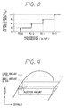
- the temperature setting lever 51 is temperature setting means for setting a target value of the air to be blown into the passenger compartment, and the control unit 40 determines, in the heating operation mode, a target value of the air heating degree in the inside heat exchanger (more specifically, the pressure of the refrigerant discharged from the compressor 22, i.e., the high-pressure side pressure) according to the set position of the lever 51, as shown in the characteristics of FIG. 3.
- the control unit 40 determines that a target value of the air cooling degree in the inside heat exchanger 14 (more specifically, the temperature of the air having just passed through the heat exchanger 14) according to the set position of the lever 51, as shown in the characteristics of FIG. 4.
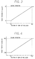
- the temperature setting lever 51 functions also as a lever which determines an operation mode of the refrigeration cycle 21, and the control unit 40 switches the operation mode of the refrigeration cycle 21 according to the set position of the lever 51. That is, the control unit 40 controls the four way valve 23 such that the operation mode of the refrigeration cycle 21 is changed from the cooling operation mode to the heating operation mode according to a movement of the lever 51 from the left side to the right side in FIG. 2.
- control unit 40 there is provided a microcomputer (not shown) composed of a CPU, a ROM, a RAM and the like, and signals from each of sensors and the control panel 50 are input to the microcomputer through an input circuit (not shown) in the control unit 40.
- a microcomputer (not shown) composed of a CPU, a ROM, a RAM and the like, and signals from each of sensors and the control panel 50 are input to the microcomputer through an input circuit (not shown) in the control unit 40.
- the microcomputer performs a predetermined process (described later) and controls based on the result the fan motor 7a, the electromagnetic four way valves 23, the electric outside fan 24a, the inverter 30, and the like.
- the control unit 40 is supplied with an electric current from the battery 31 when a key switch (not shown) of the vehicle is turned on.
- the refrigerant flowed out of the outside heat exchanger 24 passes through the check valve 28d and is decompressed in the fixed throttle to be in gas and liquid two phase state having an intermediate pressure.
- the liquid refrigerant in the gas-liquid separator 25 flows out through a liquid refrigerant outlet 25b opened adjacent to a bottom portion of the gas-liquid separator 25, and is decompressed in the temperature responding type expansion valve to be in gas and liquid two phase state having a low temperature and a low pressure.
- the low-pressure refrigerant after having passed through the check valve 28a, flows into the inside heat exchanger 14.
- the refrigerant in the heat exchanger 14 evaporates while absorbing the air blown by the blower 6.
- the cool air, cooled while a heat of which is absorbed in the heat exchanger 14, is usually blown out into the passenger compartment through the face air outlet 9. In this way, the cooling operation for the passenger compartment is performed.
- the gas refrigerant evaporated in the cooling inside heat exchanger 14 is sucked from the refrigerant suction passage 22e into the suction port 22b of the compressor 22.
- the temperature of the refrigerant to be sucked into the compressor 22 is detected by the temperature sensing bulb 27a and is transmitted to the expansion valve 27; and therefore, the expansion valve 27 adjusts an amount of the refrigerant flowing into the heat exchanger 14 in such a manner that the refrigerant to be sucked into the compressor 22 has a predetermined superheating degree.
- the high-pressure refrigerant discharged from the compressor 22 passes through the four way valve 23, flows into the inside heat exchanger 14 at first, and the gas refrigerant is condensed therein by being heat-exchanged with air blown by the blower 6.
- the warm air, heated by radiating the condensation latent heat of the gas refrigerant, is blown out into the passenger compartment mainly through the foot air outlet 8. In this way, the heating operation for the passenger compartment is performed.
- the inside heat exchanger 14 flowed out of the inside heat exchanger 14 passes through the check valve 28b, and then is decompressed in the fixed throttle 26 to be in gas and liquid two phase state having an intermediate pressure.
- the gas and liquid two phase refrigerant having the intermediate pressure flows into the gas-liquid separator 25, and the separated gas refrigerant flows from the gas refrigerant outlet 25a on the upper portion of the gas-liquid separator 25 through the gas injection passage 22d and the check valve 28e to the gas injection port 22c.
- the liquid refrigerant in the gas-liquid separator 25 flows out through the liquid refrigerant outlet 25b and is decompressed in the temperature responding type expansion valve.
- the refrigerant after having passed through the check valve 28c, flows into the outside heat exchanger 24.
- the refrigerant in the outside heat exchanger 24 evaporates while absorbing the air (outside air) blown by the outside blower 24a.
- the gas refrigerant evaporated in the outside heat exchanger 24 passes through the four way valve 23 and is sucked into the suction port 22b of the compressor 22 through the refrigerant suction passage 22e.
- a routine of FIG. 5 is started.
- a set position of the temperature setting lever 51 of the air conditioning control panel 50 is read.
- the target high-pressure side pressure PO corresponding to the set position of the temperature setting lever 51 is determined according to the characteristics of FIG. 3 (a map stored in the ROM).
- an actual high pressure detected by the pressure sensor 41 is read.
- a rotational speed of the compressor 22 is controlled in such a manner that the actual high pressure is set to the target high pressure side pressure PO. More specifically, a deviation between the actual high pressure and the target high pressure side pressure PO is calculated, and an electric power supplied to the electric motor of the compressor 22 is controlled by the inverter 29 according to the deviation.
- an air amount BO set by the air amount switching lever 52 in the air conditioning control panel 50 is read.
- an upper limit value BP of the air amount of the blower is determined based on the actual high pressure detected by the pressure sensor 41 according to the characteristics of FIG. 6 (a map stored in the ROM).
- the characteristics of FIG. 6 will be described.
- the abscissa represents the actual high pressure detected by the pressure sensor 41
- the divisions of PO-4 to PO-1 mean the pressure values which are the target high-pressure side pressure PO minus 4 to 1 (Kg/cm 2 ), respectively.
- the ordinate represents the air amount level of the blower 6, and the air amount increases stepwise from Lo to Hi.
- the upper limit value BP of the air amount of the blower 6 is set to the Mel level.
- step 107 it is determined whether the set air amount BO is larger than the upper limit value BP.
- the set air amount BO is larger than the upper limit value BP, it proceeds to step 108, and the air amount of the blower 6 is compulsorily set to the upper limit value BP.
- the upper limit value BP is set to be smaller in accordance with a decrease of the actual high pressure; and therefore, the air amount of the blower 6 is compulsorily restricted to a smaller value in accordance with a decrease of the actual high pressure. That is, immediately after the heating operation is started in a case of low-temperature outside air, even if an user set the set air amount BO for the Hi-level shown in FIG. 6, for example, when the actual high pressure is low, the air amount of the blower 6 is compulsorily restricted to a small value.
- the high-pressure side pressure increases as compared with when the large amount of air (e.g., Hi-level).
- the intermediate pressure increases as shown in a Mollier diagram shown by a chain line in FIG. 9 so that the amount of the gas injection increases.
- the amount of the refrigerant circulating into the inside heat exchanger 14 increases so that the heating capacity can be improved.
- the high-pressure side pressure further increases, with the result that the heating capacity is further improved.
- step 107 when it is determined that the set air amount is smaller than the upper limit value BP, it proceeds to step 109, and the air amount of the blower 6 is set to the set air amount BO.
- the air amount level is set to a OFF, and the blower 6 is stopped to increase the high-pressure side pressure rapidly.
- the air amount of the blower 6 (the amount of the air passing through the inside heat exchanger 14) can be restricted within the upper limit value BP determined based on the high-pressure side pressure of the refrigeration cycle; and therefore, the high-pressure side pressure can be increased as compared with when the large amount of the air is set, the amount of the gas injection is increased to improve the heating capacity.
- the step 106 constructs air amount upper limit value determination means for determining the upper limit value BP of the amount of the air passing through the inside heat exchanger 14, and the step 107 constructs determination means for determining whether or not the set air amount set by the air amount switching lever (air amount setting means) 52 is larger than the upper limit value BP. Further, the step 108 constructs first control means for restricting the amount of the air passing through the inside heat exchanger 14 to the upper limit value BP when it is determined that the set air amount BO is larger than the upper limit value BP, and the step 109 constructs second control means for setting the amount of the air passing through the inside heat exchanger 14 to the set air amount BO.
- a bypass passage 15 is formed at a side of the inside heat exchanger 14 in the duct 2, and there is provided an air mixing door 16 (door member) for separating air passing through the inside heat exchanger 14 and air passing through the bypass passage 15.
- an opening degree of the air mixing door 16 the amount of the air passing through the inside heat exchanger 14 can be controlled.
- the air mixing door 16 is actuated by an electric actuator such as a servomotor, and the opening degree of the air mixing door 16 is determined based on the actual high pressure detected by the pressure sensor 41, according to characteristics of FIG. 8 (a map stored in the ROM).
- the opening degree 100 % is an opening position where the air mixing door 16 is operated to a position shown by the solid line so that all amount of air passes through the inside heat exchanger 14, whereas the smallest opening degree 20 % is an opening position where 20 % of the amount of the air blown by the blower 6 passes through the inside heat exchanger 14 and 80 % of the air amount passes through the bypass passage 15.
- the smallest opening degree of the air mixing door 16 is set to 20 %, even if the high-pressure side pressure lowers, the amount of the air passing through the inside heat exchanger 14 cannot be set for zero.
- all of the switching points for switching the air amount level of the upper limit value BP is set to interlock with the target high pressure Po; however, the switching point (PO-4) at the lowest pressure side may be fixed to a predetermined value (for example, 7 Kg/cm 2 ). In this way, the switching point for switching the air amount level from OFF to Lo-level can be fixed to the identical high pressure irrespective of the target high pressure PO.
- the switching point (PO-4) at the smallest opening degree side of the air mixing door may be fixed to a predetermined value (for example, 7 Kg/cm 2 ).
- the blower 6 when the actual high pressure decreases to be lower than PO-4 shown in FIG. 6, the blower 6 is stopped; however, without stopping the blower 6, the predetermined smallest amount of air may pass through the inside heat exchanger 14, as in the second embodiment.
- the high-pressure side pressure of the refrigeration cycle is directly detected by the pressure sensor 41; however, without detecting the high-pressure side pressure, a temperature of the air having been just blown out from the inside heat exchanger 14 may be detected, and the upper limit value BP of the amount of the air passing through the inside heat exchanger 14 may be determined based on this detection temperature. Similarly, a temperature of the gas refrigerant discharged from the compressor 22 may be detected. The important thing is that any kinds of physical values relative to the high-pressure side pressure of the refrigeration cycle may be detected.
- the air amount of the blower 6 is set by the air amount switching lever 52 which is manually operated; however, it has been known well that the air amount of the blower 6 is automatically set based on the target temperature of the blown-air in the automotive air conditioning apparatus, and the present invention may be employed in such an air amount automatic setting type.
- the blower since the set air amount BO at step 105 is set to the air amount which is automatically set, the blower operates with the air amount which is automatically set.
Landscapes
- Engineering & Computer Science (AREA)
- Physics & Mathematics (AREA)
- Thermal Sciences (AREA)
- Mechanical Engineering (AREA)
- General Engineering & Computer Science (AREA)
- Air-Conditioning For Vehicles (AREA)
- Compression-Type Refrigeration Machines With Reversible Cycles (AREA)
Applications Claiming Priority (3)
| Application Number | Priority Date | Filing Date | Title |
|---|---|---|---|
| JP183722/96 | 1996-07-12 | ||
| JP8183722A JPH1026430A (ja) | 1996-07-12 | 1996-07-12 | ガスインジェクション式ヒートポンプ装置 |
| JP18372296 | 1996-07-12 |
Publications (3)
| Publication Number | Publication Date |
|---|---|
| EP0818333A2 true EP0818333A2 (de) | 1998-01-14 |
| EP0818333A3 EP0818333A3 (de) | 2000-12-13 |
| EP0818333B1 EP0818333B1 (de) | 2001-12-05 |
Family
ID=16140825
Family Applications (1)
| Application Number | Title | Priority Date | Filing Date |
|---|---|---|---|
| EP97111314A Expired - Lifetime EP0818333B1 (de) | 1996-07-12 | 1997-07-04 | Wärmepumpe des Gaseinspritztyps |
Country Status (4)
| Country | Link |
|---|---|
| US (1) | US5778691A (de) |
| EP (1) | EP0818333B1 (de) |
| JP (1) | JPH1026430A (de) |
| DE (1) | DE69708769T2 (de) |
Cited By (2)
| Publication number | Priority date | Publication date | Assignee | Title |
|---|---|---|---|---|
| FR2957851A1 (fr) * | 2010-03-26 | 2011-09-30 | Valeo Systemes Thermiques | Dispositif de chauffage, ventilation et/ou climatisation pour vehicule automobile |
| FR2957850A1 (fr) * | 2010-03-26 | 2011-09-30 | Valeo Systemes Thermiques | Dispositif de chauffage, ventilation et/ou climatisation pour vehicule automobile |
Families Citing this family (14)
| Publication number | Priority date | Publication date | Assignee | Title |
|---|---|---|---|---|
| JP3890713B2 (ja) * | 1997-11-27 | 2007-03-07 | 株式会社デンソー | 冷凍サイクル装置 |
| US5996360A (en) * | 1997-11-27 | 1999-12-07 | Denso Corporation | Refrigerant cycle system |
| CN1993040B (zh) * | 2004-07-13 | 2011-12-28 | 德拉瓦尔控股股份有限公司 | 挤奶系统、真空源和提供真空的方法 |
| JP5042058B2 (ja) * | 2008-02-07 | 2012-10-03 | 三菱電機株式会社 | ヒートポンプ式給湯用室外機及びヒートポンプ式給湯装置 |
| FR2963665B1 (fr) * | 2010-08-05 | 2015-10-16 | Valeo Systemes Thermiques | Boucle de climatisation comprenant un dispositif de reception d'un fluide refrigerant |
| JP5413393B2 (ja) * | 2011-03-28 | 2014-02-12 | 株式会社デンソー | 冷媒分配器および冷凍サイクル |
| JP5759017B2 (ja) | 2011-12-22 | 2015-08-05 | 三菱電機株式会社 | 空気調和装置 |
| US9452659B2 (en) | 2012-12-31 | 2016-09-27 | GM Global Technology Operations LLC | Method and apparatus for controlling a combined heating and cooling vapor compression system |
| JP5949648B2 (ja) * | 2013-04-18 | 2016-07-13 | 株式会社デンソー | 冷凍サイクル装置 |
| EP2969673B1 (de) * | 2013-04-28 | 2020-03-18 | BYD Company Limited | Enteisungsvorrichtung und fahrzeug damit |
| JP6189098B2 (ja) * | 2013-06-14 | 2017-08-30 | 三菱重工オートモーティブサーマルシステムズ株式会社 | ヒートポンプ式車両用空調システム |
| JP6223753B2 (ja) * | 2013-09-04 | 2017-11-01 | サンデンホールディングス株式会社 | 車両用空気調和装置 |
| WO2016125697A1 (ja) * | 2015-02-04 | 2016-08-11 | 株式会社デンソー | 統合弁およびヒートポンプサイクル |
| US11267318B2 (en) * | 2019-11-26 | 2022-03-08 | Ford Global Technologies, Llc | Vapor injection heat pump system and controls |
Citations (1)
| Publication number | Priority date | Publication date | Assignee | Title |
|---|---|---|---|---|
| EP0756954A2 (de) | 1995-08-01 | 1997-02-05 | Nippondenso Co., Ltd. | Klimaanlage |
Family Cites Families (8)
| Publication number | Priority date | Publication date | Assignee | Title |
|---|---|---|---|---|
| US4344297A (en) * | 1980-03-20 | 1982-08-17 | Daikin Kogyo Co., Ltd. | Refrigeration system |
| JPS63116060A (ja) * | 1986-11-04 | 1988-05-20 | トヨタ自動車株式会社 | 冷凍装置 |
| US4860552A (en) * | 1988-12-23 | 1989-08-29 | Honeywell, Inc. | Heat pump fan control |
| JPH03156251A (ja) * | 1989-11-10 | 1991-07-04 | Toshiba Corp | 液インジェクション制御装置 |
| JP3051420B2 (ja) * | 1990-03-02 | 2000-06-12 | 株式会社日立製作所 | 空気調和装置,その装置に用いられる室内熱交換器の製造方法 |
| JP2964705B2 (ja) * | 1991-06-13 | 1999-10-18 | ダイキン工業株式会社 | 空気調和装置 |
| US5533352A (en) * | 1994-06-14 | 1996-07-09 | Copeland Corporation | Forced air heat exchanging system with variable fan speed control |
| JP3305883B2 (ja) * | 1994-07-06 | 2002-07-24 | サンデン株式会社 | 車両用空気調和装置 |
-
1996
- 1996-07-12 JP JP8183722A patent/JPH1026430A/ja not_active Withdrawn
-
1997
- 1997-07-04 DE DE69708769T patent/DE69708769T2/de not_active Expired - Fee Related
- 1997-07-04 EP EP97111314A patent/EP0818333B1/de not_active Expired - Lifetime
- 1997-07-08 US US08/889,216 patent/US5778691A/en not_active Expired - Fee Related
Patent Citations (1)
| Publication number | Priority date | Publication date | Assignee | Title |
|---|---|---|---|---|
| EP0756954A2 (de) | 1995-08-01 | 1997-02-05 | Nippondenso Co., Ltd. | Klimaanlage |
Cited By (2)
| Publication number | Priority date | Publication date | Assignee | Title |
|---|---|---|---|---|
| FR2957851A1 (fr) * | 2010-03-26 | 2011-09-30 | Valeo Systemes Thermiques | Dispositif de chauffage, ventilation et/ou climatisation pour vehicule automobile |
| FR2957850A1 (fr) * | 2010-03-26 | 2011-09-30 | Valeo Systemes Thermiques | Dispositif de chauffage, ventilation et/ou climatisation pour vehicule automobile |
Also Published As
| Publication number | Publication date |
|---|---|
| DE69708769T2 (de) | 2002-05-23 |
| DE69708769D1 (de) | 2002-01-17 |
| JPH1026430A (ja) | 1998-01-27 |
| EP0818333B1 (de) | 2001-12-05 |
| EP0818333A3 (de) | 2000-12-13 |
| US5778691A (en) | 1998-07-14 |
Similar Documents
| Publication | Publication Date | Title |
|---|---|---|
| US11525611B2 (en) | Refrigeration cycle device for vehicle | |
| US5704219A (en) | Air conditioning apparatus | |
| JP3952545B2 (ja) | 車両用空調装置 | |
| US5704217A (en) | Air conditioner for vehicle, improved for frost deposition | |
| EP0818333B1 (de) | Wärmepumpe des Gaseinspritztyps | |
| JP3890713B2 (ja) | 冷凍サイクル装置 | |
| JP6065637B2 (ja) | 冷却システム | |
| US5996360A (en) | Refrigerant cycle system | |
| US5669231A (en) | Air conditioning apparatus | |
| US6058728A (en) | Refrigerant cycle for vehicle air conditioner | |
| CN104412050B (zh) | 热泵循环系统 | |
| JP2001324237A (ja) | 冷凍サイクル装置 | |
| US7082990B1 (en) | Air conditioning apparatus for vehicle | |
| US5709098A (en) | Air conditioning apparatus | |
| US5769316A (en) | Air conditioner for vehicles | |
| JP3334446B2 (ja) | 車両用空調装置 | |
| JP3257361B2 (ja) | 車両用空調装置 | |
| JP3063574B2 (ja) | 空調装置 | |
| JP2000283611A (ja) | ヒートポンプ式空調装置 | |
| JP2019184107A (ja) | 電池冷却装置 | |
| JP3063575B2 (ja) | 冷凍サイクル制御装置 | |
| JP4285228B2 (ja) | 車両用空調装置 | |
| JPH10115448A (ja) | 空調装置 | |
| JP2000291995A (ja) | 空調装置 | |
| JP3893718B2 (ja) | 空調装置 |
Legal Events
| Date | Code | Title | Description |
|---|---|---|---|
| PUAI | Public reference made under article 153(3) epc to a published international application that has entered the european phase |
Free format text: ORIGINAL CODE: 0009012 |
|
| AK | Designated contracting states |
Kind code of ref document: A2 Designated state(s): DE FR IT |
|
| PUAL | Search report despatched |
Free format text: ORIGINAL CODE: 0009013 |
|
| AK | Designated contracting states |
Kind code of ref document: A3 Designated state(s): AT BE CH DE DK ES FI FR GB GR IE IT LI LU MC NL PT SE |
|
| RIC1 | Information provided on ipc code assigned before grant |
Free format text: 7B 60H 1/00 A, 7F 25B 49/02 B |
|
| 17P | Request for examination filed |
Effective date: 20001123 |
|
| GRAG | Despatch of communication of intention to grant |
Free format text: ORIGINAL CODE: EPIDOS AGRA |
|
| 17Q | First examination report despatched |
Effective date: 20010329 |
|
| GRAG | Despatch of communication of intention to grant |
Free format text: ORIGINAL CODE: EPIDOS AGRA |
|
| GRAH | Despatch of communication of intention to grant a patent |
Free format text: ORIGINAL CODE: EPIDOS IGRA |
|
| AKX | Designation fees paid |
Free format text: DE FR IT |
|
| GRAH | Despatch of communication of intention to grant a patent |
Free format text: ORIGINAL CODE: EPIDOS IGRA |
|
| GRAA | (expected) grant |
Free format text: ORIGINAL CODE: 0009210 |
|
| AK | Designated contracting states |
Kind code of ref document: B1 Designated state(s): DE FR IT |
|
| REF | Corresponds to: |
Ref document number: 69708769 Country of ref document: DE Date of ref document: 20020117 |
|
| ET | Fr: translation filed | ||
| PGFP | Annual fee paid to national office [announced via postgrant information from national office to epo] |
Ref country code: FR Payment date: 20020709 Year of fee payment: 6 |
|
| PGFP | Annual fee paid to national office [announced via postgrant information from national office to epo] |
Ref country code: DE Payment date: 20020710 Year of fee payment: 6 |
|
| PLBE | No opposition filed within time limit |
Free format text: ORIGINAL CODE: 0009261 |
|
| STAA | Information on the status of an ep patent application or granted ep patent |
Free format text: STATUS: NO OPPOSITION FILED WITHIN TIME LIMIT |
|
| 26N | No opposition filed | ||
| PG25 | Lapsed in a contracting state [announced via postgrant information from national office to epo] |
Ref country code: DE Free format text: LAPSE BECAUSE OF NON-PAYMENT OF DUE FEES Effective date: 20040203 |
|
| PG25 | Lapsed in a contracting state [announced via postgrant information from national office to epo] |
Ref country code: FR Free format text: LAPSE BECAUSE OF NON-PAYMENT OF DUE FEES Effective date: 20040331 |
|
| REG | Reference to a national code |
Ref country code: FR Ref legal event code: ST |
|
| PG25 | Lapsed in a contracting state [announced via postgrant information from national office to epo] |
Ref country code: IT Free format text: LAPSE BECAUSE OF NON-PAYMENT OF DUE FEES;WARNING: LAPSES OF ITALIAN PATENTS WITH EFFECTIVE DATE BEFORE 2007 MAY HAVE OCCURRED AT ANY TIME BEFORE 2007. THE CORRECT EFFECTIVE DATE MAY BE DIFFERENT FROM THE ONE RECORDED. Effective date: 20050704 |