EP0818345B1 - Palier avant pour sièges de véhicules automobiles - Google Patents
Palier avant pour sièges de véhicules automobiles Download PDFInfo
- Publication number
- EP0818345B1 EP0818345B1 EP97110113A EP97110113A EP0818345B1 EP 0818345 B1 EP0818345 B1 EP 0818345B1 EP 97110113 A EP97110113 A EP 97110113A EP 97110113 A EP97110113 A EP 97110113A EP 0818345 B1 EP0818345 B1 EP 0818345B1
- Authority
- EP
- European Patent Office
- Prior art keywords
- guide
- mounting according
- guide base
- base
- middle rail
- Prior art date
- Legal status (The legal status is an assumption and is not a legal conclusion. Google has not performed a legal analysis and makes no representation as to the accuracy of the status listed.)
- Expired - Lifetime
Links
- 239000002184 metal Substances 0.000 claims description 7
- 210000002105 tongue Anatomy 0.000 claims description 7
- 238000006073 displacement reaction Methods 0.000 claims description 3
- 230000037431 insertion Effects 0.000 claims 4
- 238000003780 insertion Methods 0.000 claims 4
- 238000007373 indentation Methods 0.000 claims 1
- 238000009434 installation Methods 0.000 description 1
- 230000003993 interaction Effects 0.000 description 1
- 239000000463 material Substances 0.000 description 1
Images

Classifications
-
- B—PERFORMING OPERATIONS; TRANSPORTING
- B60—VEHICLES IN GENERAL
- B60N—SEATS SPECIALLY ADAPTED FOR VEHICLES; VEHICLE PASSENGER ACCOMMODATION NOT OTHERWISE PROVIDED FOR
- B60N2/00—Seats specially adapted for vehicles; Arrangement or mounting of seats in vehicles
- B60N2/02—Seats specially adapted for vehicles; Arrangement or mounting of seats in vehicles the seat or part thereof being movable, e.g. adjustable
- B60N2/04—Seats specially adapted for vehicles; Arrangement or mounting of seats in vehicles the seat or part thereof being movable, e.g. adjustable the whole seat being movable
- B60N2/06—Seats specially adapted for vehicles; Arrangement or mounting of seats in vehicles the seat or part thereof being movable, e.g. adjustable the whole seat being movable slidable
- B60N2/08—Seats specially adapted for vehicles; Arrangement or mounting of seats in vehicles the seat or part thereof being movable, e.g. adjustable the whole seat being movable slidable characterised by the locking device
- B60N2/0812—Location of the latch
- B60N2/0825—Location of the latch outside the rail
-
- B—PERFORMING OPERATIONS; TRANSPORTING
- B60—VEHICLES IN GENERAL
- B60N—SEATS SPECIALLY ADAPTED FOR VEHICLES; VEHICLE PASSENGER ACCOMMODATION NOT OTHERWISE PROVIDED FOR
- B60N2/00—Seats specially adapted for vehicles; Arrangement or mounting of seats in vehicles
- B60N2/02—Seats specially adapted for vehicles; Arrangement or mounting of seats in vehicles the seat or part thereof being movable, e.g. adjustable
- B60N2/04—Seats specially adapted for vehicles; Arrangement or mounting of seats in vehicles the seat or part thereof being movable, e.g. adjustable the whole seat being movable
- B60N2/06—Seats specially adapted for vehicles; Arrangement or mounting of seats in vehicles the seat or part thereof being movable, e.g. adjustable the whole seat being movable slidable
- B60N2/07—Slide construction
- B60N2/0702—Slide construction characterised by its cross-section
- B60N2/0705—Slide construction characterised by its cross-section omega-shaped
-
- B—PERFORMING OPERATIONS; TRANSPORTING
- B60—VEHICLES IN GENERAL
- B60N—SEATS SPECIALLY ADAPTED FOR VEHICLES; VEHICLE PASSENGER ACCOMMODATION NOT OTHERWISE PROVIDED FOR
- B60N2/00—Seats specially adapted for vehicles; Arrangement or mounting of seats in vehicles
- B60N2/02—Seats specially adapted for vehicles; Arrangement or mounting of seats in vehicles the seat or part thereof being movable, e.g. adjustable
- B60N2/04—Seats specially adapted for vehicles; Arrangement or mounting of seats in vehicles the seat or part thereof being movable, e.g. adjustable the whole seat being movable
- B60N2/06—Seats specially adapted for vehicles; Arrangement or mounting of seats in vehicles the seat or part thereof being movable, e.g. adjustable the whole seat being movable slidable
- B60N2/07—Slide construction
- B60N2/0702—Slide construction characterised by its cross-section
- B60N2/0715—C or U-shaped
-
- B—PERFORMING OPERATIONS; TRANSPORTING
- B60—VEHICLES IN GENERAL
- B60N—SEATS SPECIALLY ADAPTED FOR VEHICLES; VEHICLE PASSENGER ACCOMMODATION NOT OTHERWISE PROVIDED FOR
- B60N2/00—Seats specially adapted for vehicles; Arrangement or mounting of seats in vehicles
- B60N2/02—Seats specially adapted for vehicles; Arrangement or mounting of seats in vehicles the seat or part thereof being movable, e.g. adjustable
- B60N2/04—Seats specially adapted for vehicles; Arrangement or mounting of seats in vehicles the seat or part thereof being movable, e.g. adjustable the whole seat being movable
- B60N2/06—Seats specially adapted for vehicles; Arrangement or mounting of seats in vehicles the seat or part thereof being movable, e.g. adjustable the whole seat being movable slidable
- B60N2/08—Seats specially adapted for vehicles; Arrangement or mounting of seats in vehicles the seat or part thereof being movable, e.g. adjustable the whole seat being movable slidable characterised by the locking device
- B60N2/0831—Movement of the latch
- B60N2/0862—Movement of the latch sliding
- B60N2/0868—Movement of the latch sliding in a transversal direction
Definitions
- the invention relates to the front mounting of a vehicle seat according to, e.g. generic term disclosed in document US 5 275 369 A of claim 1.
- the central rail is Z-shaped in cross section. It prevails a recess in the guide bracket welded to the seat cross member fixed to the body, on which a spring-loaded bolt displaceable in the transverse direction of the vehicle is mounted is one of several one behind the other for the purpose of locking the longitudinally displaceable seat holes arranged in the vertical web of the rail.
- the spacing of the holes in the rail indicates the step size for the longitudinal adjustment of the seat.
- the invention has for its object this known and proven thousands of times storage continue to improve.
- the function of the front guide should be checked be possible outside the vehicle.
- a better mounting option is said be achieved when installing the seat in the vehicle, also with regard to a mechanized one Assembly.
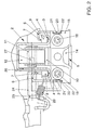
- a middle rail 2 On a frame 1 of a longitudinally displaceable seat is a middle rail 2 attached, which is quasi hat-shaped in cross section. More precisely, the shows Cross-section of a U with the opening facing downwards, the free ends of the legs towards have outwardly projecting flanges 3 which lead to guide channels 4 which are open at the top are formed.
- a guide block designated overall by 5, which also a substantially U-shaped cross-section with at its free leg ends has inward projections 6, which in turn with downward, web-like Sections 7 are provided.
- plastic sliders 8, 9 plugged in, which dip into the guide channels 4.
- the plastic glider 8 serves quasi as hold-down for the middle rail 2, d. that is, it lies with its underside on the Channel floor while he has plenty of play on the side.
- the slider 9 takes over lateral guidance of the middle rail 2, d. that is, it rests elastically on the side walls of the guide channel while there is enough air between its bottom and the channel bottom is.
- a bearing block 10 Integrated into the guide block 5 is a bearing block 10 with a cross to the direction of displacement of the seat extending bearing sleeve 11 for receiving a roller 12 as a support element for the Middle rail 2.
- the roller 12 considerably facilitates the longitudinal displacement of the seat.
- the guide bracket 5 also has its attachment to a cross member fixed to the body 13 an end face 14, the one welded to the cross member 13 mounting plate 15 is assigned.
- the end face 14 and the mounting plate 15 are threaded holes 16 or through holes 17 are provided for screws 18, by means of which a detachable Connection between the cross member 13 and the guide bracket 5 can be produced.
- the guide block 5 is part of the seat, so to speak (and not, as in the known one Storage, part of the body); the interaction of the guide frame 5 and the middle rail 2 can be checked before installing the seat in the vehicle and if necessary Getting corrected.
- the seat is installed in such a way that it is attached to the Center rail 2 pre-assembled guide block 5 in the direction of travel (this is indicated by arrow 19 marked) is moved against the cross member 13 until the end face 14 of the guide block 5 meets the mounting plate 15. If the threaded holes 16 and Through holes 17 are aligned with each other, the screws 18 are attached and tightened.
- the mounting plate 15 has two recesses on the side 20 on which guide elements 21 projecting forwardly from the end face 14 are assigned are. These are designed as essentially vertically aligned sheet metal tongues, which have hook-shaped sections 22 as holding elements in the exemplary embodiment.
- the sheet metal tongues 21 are threaded into the cutouts 20, and the hook-shaped sections 22 each engage behind one of the cutouts 20 Wall section of the mounting plate 15. This is prepositioning given the seat in which the mounting holes 16, 17 are aligned, on the other hand the seat is temporarily held in this position, so that the guide bracket 5 on the mounting plate 15 can be screwed. Threading the sheet metal tongues 21 into the recesses 20 is made even easier if the sheet metal tongues 21 do not run parallel to one another, but are somewhat spread in the direction of installation.
- the sheet metal tongues 21 - instead of having the hook-shaped sections 22 - also be wedge-shaped. With this, one reaches with regard to those lying in alignment Mounting holes 16, 17 better centering when assembling the guide block 5 and mounting plate 15. In this case too, before screwing a lifting of the positioning of the guide block 5 by slipping back To avoid sitting, it is advisable to use a double-acting locking clip as a holding element (not shown in the drawing) to be used with one of its end areas in a Opening in the end face 14 is pre-assembled. Its other end area snaps while the Guide block 5 is guided in the seat assembly against the mounting plate 15 in a Counter opening in the mounting plate 15.
- the locking clip is advantageously in the area its transverse median plane with a stop plate, which on the one hand slips the locking clip prevented by the opening or counter opening and the other with one suitable choice of material for the locking clip, for example rubber or an elastic Plastic, ensures that the metallic end face 14 is not directly on the metallic Fastening plate 15 rests, making undesirable noises in this area be avoided. If necessary, the locking clip can be almost over thanks to one the entire length of the recess is compressed and released from its catches be solved.
- a spring-loaded (spring 23) transversely in a sleeve 24 rigidly attached to the guide bracket 5 for the sliding direction of the seat slidably mounted pin 25 is provided, the one of several openings arranged one behind the other in the leg 26 of the middle rail 2 enforced and thus a positive connection between the guide block 5 and Middle rail 2 produces.
- the free end 27 of the bolt 25 dips into the bearing sleeve 11 a.
- Unlocking takes place by actuating an unlocking lever 28.
Landscapes
- Engineering & Computer Science (AREA)
- Aviation & Aerospace Engineering (AREA)
- Transportation (AREA)
- Mechanical Engineering (AREA)
- Seats For Vehicles (AREA)
- Road Paving Machines (AREA)
Claims (15)
- Fixation avant d'un siège de voiture automobile (1) reposant sur le plancher de la voiture (13) par l'intermédiaire d'un point de fixation avant et de deux points de fixation arrière avecun rail central (2) fixé au siège de la voiture et servant au déplacement longitudinal du siège (1),un support de guidage (5) servant d'élément de guidage pour le rail central (2) et pouvant être fixé de manière amovible sur une traverse solidaire du plancher (13) etun dispositif d'arrêt (25) pouvant être neutralisé, qui est situé entre le rail central (2) et le support de guidage (5), caractériséeen ce que le rail central (2) est réalisé comme profilé en U renversé comprenant aux extrémités libres des branches des brides (3) dépassant vers l'extérieur,en ce que le support de guidage (5) a une section sensiblement en forme de U comprenant à ses extrémités libres des branches des prolongements (6) dirigés vers l'intérieur et qui recouvrent les brides (3) du rail central (2),en ce que le support de guidage (5) comprend un support d'appui (10) incluant une roulette (12), qui est mobile autour d'un axe perpendiculaire au rail central (2) et sur laquelle s'appuie la surface de base du rail central (2)et en ce que le support de guidage (5) comprend une surface frontale (14) pour sa fixation amovible sur la traverse (13).
- Fixation selon la revendication 1, caractérisée en ce qu'à leurs extrémités les brides (3) comprennent des nervures dirigées vers le haut, qui délimitent respectivement vers l'extérieur un canal de guidage en forme de U (4) et en ce que les prolongements (6) du support de guidage (5) comprennent des sections (7) dirigées vers le bas et pénétrant dans les canaux de guidage (4).
- Fixation selon la revendication 2, caractérisée en ce que les extrémités libres des sections (7) sont munies de patins de glissement (8, 9) dont l'un (8) s'appuie sur le fond du canal de guidage correspondant (4) tandis que l'autre (9) sert de guidage en direction transversale.
- Fixation selon l'une des revendications 1 à 3, caractérisée en ce qu'à la surface frontale (14) est attribuée une plaque de fixation (15), qui est reliée à la traverse (13), et qui permet de réaliser une liaison du support de guidage (5) au moyen d'un ensemble de vis (18).
- Fixation selon la revendication 4, caractérisée en ce que la plaque de fixation (15) comprend au moins un évidement (20), auquel est attribué comme aide au montage un élément de guidage (21) qui, en direction de montage (19) du siège (1), dépasse de la surface frontale (14) du support de guidage (5).
- Fixation selon la revendication 5, caractérisée en ce que l'autre élément de guidage (21) est réalisé avec un rétrécissement en direction de montage (19).
- Fixation selon la revendication 5 ou 6 avec deux évidements (20) dans la plaque de fixation (15) et deux éléments de guidage (21), caractérisée en ce que les autres éléments de guidage (21) réalisés comme languettes de tôle, disposées au moins approximativement en position verticale, s'écartent entre elles en direction de montage (19).
- Fixation selon l'une des revendications 1 à 7, caractérisée en ce qu'en tant qu'aide au montage, un ou deux élément(s) de maintien (22) est(sont) fixé(s) sur la surface frontale (14) du support de guidage (5), avec lequel(lesquels) le support de guidage (5) est maintenu librement sur la traverse (13) lors du montage du siège (1), avant la fixation définitive du support de guidage (5) sur la traverse (13).
- Fixation selon les revendications 8 et 7, caractérisée en ce que les éléments de maintien sont composés de sections en forme de crochets (22), qui pénètrent derrière la plaque de fixation (15) et qui sont respectivement formées sur les éléments de guidage réalisés en tant que languettes de tôle (21)
- Fixation selon la revendication 8, caractérisée en ce qu'au moins un élément de maintien est formé par une griffe d'arrêt maintenue dans la surface frontale (14) du support de guidage (5).
- Fixation selon la revendication 10, caractérisée en ce que chaque griffe d'arrêt peut s'emboíter aussi bien dans la surface frontale (14) que dans la plaque de fixation (15).
- Fixation selon la revendication 11, caractérisée en ce que chaque griffe d'arrêt est réalisée de manière sensiblement symétrique à son plan médian transversal.
- Fixation selon la revendication 12, caractérisée en ce que dans la zone du plan médian transversal une plaque d'arrêt agissant des deux côtés est formée sur chaque griffe d'arrêt.
- Fixation selon l'une des revendications 10 à 13, caractérisée en ce que chaque griffe d'arrêt comprend un évidement, qui s'étend sensiblement sur l'ensemble de sa longueur et qui permet une déformation élastique de la griffe d'arrêt ainsi qu'une neutralisation conséquente de sa position d'immobilisation sur la surface frontale et/ou sur la plaque de fixation.
- Fixation selon l'une des revendications 1 à 14, caractérisée en ce que le blocage entre le rail central (2) et le support de guidage (5) a lieu à l'aide d'un goujon (25), qui est soumis à l'action d'un ressort (23), qui est placé de manière mobile dans une douille (24) reliée de façon rigide au support de guidage (5) et dont l'extrémité libre (27) pénètre dans une autre douille (11) se trouvant dans une position concentrique par rapport à l'axe de la roulette (12).
Applications Claiming Priority (2)
| Application Number | Priority Date | Filing Date | Title |
|---|---|---|---|
| DE19627707 | 1996-07-10 | ||
| DE19627707 | 1996-07-10 |
Publications (3)
| Publication Number | Publication Date |
|---|---|
| EP0818345A2 EP0818345A2 (fr) | 1998-01-14 |
| EP0818345A3 EP0818345A3 (fr) | 1999-02-03 |
| EP0818345B1 true EP0818345B1 (fr) | 2002-01-16 |
Family
ID=7799385
Family Applications (1)
| Application Number | Title | Priority Date | Filing Date |
|---|---|---|---|
| EP97110113A Expired - Lifetime EP0818345B1 (fr) | 1996-07-10 | 1997-06-20 | Palier avant pour sièges de véhicules automobiles |
Country Status (3)
| Country | Link |
|---|---|
| EP (1) | EP0818345B1 (fr) |
| DE (1) | DE59705989D1 (fr) |
| ES (1) | ES2169291T3 (fr) |
Family Cites Families (7)
| Publication number | Priority date | Publication date | Assignee | Title |
|---|---|---|---|---|
| JPH03107235U (fr) * | 1989-12-26 | 1991-11-05 | ||
| US5275369A (en) * | 1991-01-31 | 1994-01-04 | Ohi Seisakusho Co., Ltd. | Protective cover for seat sliding devices |
| US5188329A (en) * | 1991-10-23 | 1993-02-23 | Tachi-S Co. Ltd. | Structure for covering slide railing seat adjuster |
| US5209447A (en) * | 1991-11-15 | 1993-05-11 | Tachi-S Co., Ltd. | Cover structure for slide rail in seat adjuster |
| DE4304456C2 (de) * | 1992-02-25 | 1997-07-31 | Volkswagen Ag | Anordnung mit einer längsverschiebbaren Schiene und einem daran befestigten Anschlag |
| US5242143A (en) * | 1992-03-12 | 1993-09-07 | Tachi-S Co. Ltd. | Cover for slide rail of automotive seat |
| US5482243A (en) * | 1994-02-07 | 1996-01-09 | General Motors Corporation | Seat adjuster slide arrangement |
-
1997
- 1997-06-20 ES ES97110113T patent/ES2169291T3/es not_active Expired - Lifetime
- 1997-06-20 DE DE59705989T patent/DE59705989D1/de not_active Expired - Lifetime
- 1997-06-20 EP EP97110113A patent/EP0818345B1/fr not_active Expired - Lifetime
Also Published As
| Publication number | Publication date |
|---|---|
| EP0818345A2 (fr) | 1998-01-14 |
| EP0818345A3 (fr) | 1999-02-03 |
| DE59705989D1 (de) | 2002-02-21 |
| ES2169291T3 (es) | 2002-07-01 |
Similar Documents
| Publication | Publication Date | Title |
|---|---|---|
| DE3538438A1 (de) | Verstellbare befestigungseinrichtung | |
| DE102019111242A1 (de) | Linearaktuator für einen Kraftfahrzeugsitz | |
| EP0254808A2 (fr) | Appui-tête réglable en hauteur et en inclinaison, avec fenêtre centrale pour véhicules automobiles | |
| DE19939615B4 (de) | Sitzgestell für einen Sitz in Kraftfahrzeugen | |
| DE3532419C2 (fr) | ||
| DE102011009211A1 (de) | Klipsvorrichtung, Fahrzeugsitz und Kraftfahrzeug | |
| DE29713642U1 (de) | Höhenversteller für Umlenkbeschläge von Fahrzeug-Sicherheitsgurten | |
| DE2820151A1 (de) | Gleitschiene zum vorwaerts- und rueckwaertsbewegen von fahrzeugsitzen, insbesondere kraftfahrzeugsitzen | |
| DE29918558U1 (de) | Laufschiene einer Schubkastenführung mit einer Befestigungs- und Höhenjustiervorrichtung | |
| EP1439278B1 (fr) | Joint automatique pour portes avec support adjustable | |
| DE4304456C2 (de) | Anordnung mit einer längsverschiebbaren Schiene und einem daran befestigten Anschlag | |
| DE10353687B4 (de) | Befestigungssystem zum Anbringen von Fahrzeuganbauteilen am Fahrzeugdach | |
| DE20313952U1 (de) | Arretiereinrichtung einer Längsverstellvorrichtung eines Kraftfahrzeugsitzes | |
| DE4413957A1 (de) | Dachlastenträgeranordnung für Fahrzeuge | |
| DE102018008392A1 (de) | Halterung zur Befestigung einer Gepäck-Tragvorrichtung | |
| EP0818345A2 (fr) | Palier avant pour sièges de véhicules automobiles | |
| EP0063294B1 (fr) | Dispositif de fixation, en particulier pour accoudoir ou poignées à la paroi intérieure de carosserie pour véhicules | |
| DE20201327U1 (de) | Vorrichtung zum Verankern eines Sitzes an einem Fahrzeugboden | |
| DE19834412B4 (de) | Schiene für Fahrzeugsitze, Fahrzeug mit einem Sitz, der mit einer solchen Schiene ausgestattet ist, und Verankerungshaken für eine solche Schiene | |
| DE10044779B4 (de) | Längseinstellbarer Fahrzeugsitz | |
| EP0642957A2 (fr) | Dispositif de renvoi latéral réglable en hauteur pour ceintures de sécurité | |
| DE102006059096A1 (de) | Baugruppe zur fahrzeugseitigen Befestigung eines Gurtschlosses | |
| DE10208505B4 (de) | Verbindungselement, Anordnung aus Verkleidungsteil mit Verbindungselement und Dichtungsprofil und Verfahren zur Montage | |
| EP0812725A2 (fr) | Support d'appui-tête pour sièges de véhicules automobiles | |
| DE19917845C2 (de) | Schienenführung für Verstelleinrichtungen in Kraftfahrzeugen mit zwei ineinandergreifenden, in Schienenlängsrichtung zueinander verstellbaren Schienen |
Legal Events
| Date | Code | Title | Description |
|---|---|---|---|
| PUAI | Public reference made under article 153(3) epc to a published international application that has entered the european phase |
Free format text: ORIGINAL CODE: 0009012 |
|
| AK | Designated contracting states |
Kind code of ref document: A2 Designated state(s): DE ES FR GB |
|
| PUAL | Search report despatched |
Free format text: ORIGINAL CODE: 0009013 |
|
| AK | Designated contracting states |
Kind code of ref document: A3 Designated state(s): DE ES FR GB |
|
| 17P | Request for examination filed |
Effective date: 19990803 |
|
| AKX | Designation fees paid |
Free format text: DE ES FR GB |
|
| GRAG | Despatch of communication of intention to grant |
Free format text: ORIGINAL CODE: EPIDOS AGRA |
|
| GRAG | Despatch of communication of intention to grant |
Free format text: ORIGINAL CODE: EPIDOS AGRA |
|
| GRAH | Despatch of communication of intention to grant a patent |
Free format text: ORIGINAL CODE: EPIDOS IGRA |
|
| 17Q | First examination report despatched |
Effective date: 20010521 |
|
| GRAH | Despatch of communication of intention to grant a patent |
Free format text: ORIGINAL CODE: EPIDOS IGRA |
|
| GRAA | (expected) grant |
Free format text: ORIGINAL CODE: 0009210 |
|
| REG | Reference to a national code |
Ref country code: GB Ref legal event code: IF02 |
|
| AK | Designated contracting states |
Kind code of ref document: B1 Designated state(s): DE ES FR GB |
|
| REF | Corresponds to: |
Ref document number: 59705989 Country of ref document: DE Date of ref document: 20020221 |
|
| GBT | Gb: translation of ep patent filed (gb section 77(6)(a)/1977) |
Effective date: 20020406 |
|
| REG | Reference to a national code |
Ref country code: ES Ref legal event code: FG2A Ref document number: 2169291 Country of ref document: ES Kind code of ref document: T3 |
|
| ET | Fr: translation filed | ||
| PLBE | No opposition filed within time limit |
Free format text: ORIGINAL CODE: 0009261 |
|
| STAA | Information on the status of an ep patent application or granted ep patent |
Free format text: STATUS: NO OPPOSITION FILED WITHIN TIME LIMIT |
|
| 26N | No opposition filed | ||
| PGFP | Annual fee paid to national office [announced via postgrant information from national office to epo] |
Ref country code: DE Payment date: 20130630 Year of fee payment: 17 |
|
| PGFP | Annual fee paid to national office [announced via postgrant information from national office to epo] |
Ref country code: ES Payment date: 20130724 Year of fee payment: 17 |
|
| PGFP | Annual fee paid to national office [announced via postgrant information from national office to epo] |
Ref country code: GB Payment date: 20130701 Year of fee payment: 17 Ref country code: FR Payment date: 20130719 Year of fee payment: 17 |
|
| REG | Reference to a national code |
Ref country code: DE Ref legal event code: R082 Ref document number: 59705989 Country of ref document: DE |
|
| REG | Reference to a national code |
Ref country code: DE Ref legal event code: R119 Ref document number: 59705989 Country of ref document: DE |
|
| GBPC | Gb: european patent ceased through non-payment of renewal fee |
Effective date: 20140620 |
|
| REG | Reference to a national code |
Ref country code: DE Ref legal event code: R119 Ref document number: 59705989 Country of ref document: DE Effective date: 20150101 |
|
| REG | Reference to a national code |
Ref country code: FR Ref legal event code: ST Effective date: 20150227 |
|
| PG25 | Lapsed in a contracting state [announced via postgrant information from national office to epo] |
Ref country code: DE Free format text: LAPSE BECAUSE OF NON-PAYMENT OF DUE FEES Effective date: 20150101 |
|
| PG25 | Lapsed in a contracting state [announced via postgrant information from national office to epo] |
Ref country code: GB Free format text: LAPSE BECAUSE OF NON-PAYMENT OF DUE FEES Effective date: 20140620 Ref country code: FR Free format text: LAPSE BECAUSE OF NON-PAYMENT OF DUE FEES Effective date: 20140630 |
|
| REG | Reference to a national code |
Ref country code: ES Ref legal event code: FD2A Effective date: 20150724 |
|
| PG25 | Lapsed in a contracting state [announced via postgrant information from national office to epo] |
Ref country code: ES Free format text: LAPSE BECAUSE OF NON-PAYMENT OF DUE FEES Effective date: 20140621 |