EP0818370A2 - Befestigungsteil für ein Halteseil in einem Fahrzeug-Sicherheitsgurtsystem - Google Patents
Befestigungsteil für ein Halteseil in einem Fahrzeug-Sicherheitsgurtsystem Download PDFInfo
- Publication number
- EP0818370A2 EP0818370A2 EP97111299A EP97111299A EP0818370A2 EP 0818370 A2 EP0818370 A2 EP 0818370A2 EP 97111299 A EP97111299 A EP 97111299A EP 97111299 A EP97111299 A EP 97111299A EP 0818370 A2 EP0818370 A2 EP 0818370A2
- Authority
- EP
- European Patent Office
- Prior art keywords
- fastening part
- part according
- tether
- holding section
- fastening
- Prior art date
- Legal status (The legal status is an assumption and is not a legal conclusion. Google has not performed a legal analysis and makes no representation as to the accuracy of the status listed.)
- Withdrawn
Links
Images




Classifications
-
- B—PERFORMING OPERATIONS; TRANSPORTING
- B60—VEHICLES IN GENERAL
- B60R—VEHICLES, VEHICLE FITTINGS, OR VEHICLE PARTS, NOT OTHERWISE PROVIDED FOR
- B60R22/00—Safety belts or body harnesses in vehicles
- B60R22/18—Anchoring devices
-
- B—PERFORMING OPERATIONS; TRANSPORTING
- B21—MECHANICAL METAL-WORKING WITHOUT ESSENTIALLY REMOVING MATERIAL; PUNCHING METAL
- B21F—WORKING OR PROCESSING OF METAL WIRE
- B21F15/00—Connecting wire to wire or other metallic material or objects; Connecting parts by means of wire
-
- B—PERFORMING OPERATIONS; TRANSPORTING
- B21—MECHANICAL METAL-WORKING WITHOUT ESSENTIALLY REMOVING MATERIAL; PUNCHING METAL
- B21K—MAKING FORGED OR PRESSED METAL PRODUCTS, e.g. HORSE-SHOES, RIVETS, BOLTS OR WHEELS
- B21K1/00—Making machine elements
- B21K1/76—Making machine elements elements not mentioned in one of the preceding groups
-
- B—PERFORMING OPERATIONS; TRANSPORTING
- B60—VEHICLES IN GENERAL
- B60R—VEHICLES, VEHICLE FITTINGS, OR VEHICLE PARTS, NOT OTHERWISE PROVIDED FOR
- B60R22/00—Safety belts or body harnesses in vehicles
- B60R22/18—Anchoring devices
- B60R22/22—Anchoring devices secured to the vehicle floor
-
- B—PERFORMING OPERATIONS; TRANSPORTING
- B60—VEHICLES IN GENERAL
- B60R—VEHICLES, VEHICLE FITTINGS, OR VEHICLE PARTS, NOT OTHERWISE PROVIDED FOR
- B60R22/00—Safety belts or body harnesses in vehicles
- B60R22/04—Passive restraint systems, i.e. systems both applied and removed automatically, e.g. by movement of the vehicle door
- B60R22/06—Passive restraint systems, i.e. systems both applied and removed automatically, e.g. by movement of the vehicle door having the belt or harness connected to a member slidable in a vehicle-mounted track
Definitions
- the invention relates to a fastening part for a tether in a vehicle seat belt system, with a mounting sheet that is provided with a hole for a fastening screw, and a holding section into which the tether is pressed.
- Such a fastener is usually manufactured by a steel precast on one end of the tether is pushed on and pressed with it. Because of the comparative high strength of the material used for the finished part there is a high holding force for the tether in the holding section of the fastening part. However, it is precisely this high strength that with regard to the holding force of the tether in the holding part leads to advantages, both in the manufacture of the finished part as well as in the manufacture of the fastener. This Disadvantages consist in particular of a high energy expenditure for the Production or forming of the finished part and a lot of effort when pressing the finished part with the tether.
- the invention provides a fastener in which the Manufacturing or forming expense compared to steel Fasteners is significantly reduced.
- the fastening part made of aluminum or an aluminum alloy consists.
- the invention is based on that for the expert surprising finding that even with aluminum or an aluminum alloy, their strength generally below that of steel, a sufficient holding force of the tether in the Holding section can be achieved. This is particularly because it when pressing the holding section with the tether to one Strain hardening of the aluminum or the used Aluminum alloy comes due to which the strength is considerable is increased. This increase in strength ultimately leads to that the material cross-sections used of an inventive Fastening part compared to that of a conventional fastening part made of steel do not have to be increased significantly to the to achieve the same strength, while at the same time saving weight is achieved.
- the hole in the mounting sheet on a special be achieved in an advantageous manner.
- the hole is either punched out or with a Drill is drilled, the diameter of which is the diameter of the one to be produced Bore corresponds
- a fastener according to the invention first a hole is formed, the diameter of which is smaller than the diameter of the hole to be made. This hole will expanded in a subsequent processing step by means of a mandrel, which is pushed into the hole.
- too Achieving diameter of the hole and the diameter of the used Lochs can already be a single expansion step with a single one Sufficient thorn; however, it may also prove necessary perform several expansion steps in succession.
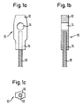
- FIGS. 1a, 1b and 1c A fastening part according to the invention is shown in FIGS. 1a, 1b and 1c shown according to a first embodiment.
- the fastener 10 has a mounting sheet 12 which with a Bore 14 is provided for a fastening screw with which the Fastening part can be attached to the vehicle.
- the fastener 10 also has a holding section 16 into which a Holding rope 18 is pressed, at the other end, for example Belt buckle of the vehicle seat belt system can be attached.
- the fastening part 10 consists of aluminum or an aluminum alloy, while the fastening part 10 'according to the prior art consists of steel.
- the tether 18 or 18 ' is used as steel in both cases.
- fastening part 10 Due to the different materials for the fastening part there are a number of design differences of the fastening part 10 relative to the fastening part 10 '.
- the fastening part according to the invention measured in one direction parallel to the longitudinal axis of the bore 14, one essentially constant thickness.
- the fastening part 10 ' according to the prior art on the mounting sheet 12 ' measured in a direction parallel to the longitudinal axis of the bore 14 ', a smaller one Thickness than the holding portion 16 '.
- the invention Fastening part 10 at the transition between the fastening sheet 12 and the holding section 16 is not constricted; the holding section 16 has thus at its end facing the fastening sheet 12, measured in a direction perpendicular to the longitudinal axis of the bore and perpendicular to Longitudinal axis of the tether, about the same width as the attachment sheet 12. Only to the free end of the holding section 16 its width is gradually reduced.
- FIGS. 3a, 3b and 3c 10 A fastening part according to the invention is shown in FIGS. 3a, 3b and 3c 10 according to a second embodiment.
- the second embodiment differs from the first embodiment in particular in that the outer edge of the holding section 16 and the mounting sheet 12 not parallel to the longitudinal axis of the tether 18 runs, but at an angle ⁇ , which is between about 3.5 ° and is about 6 °. This angle is shown in FIG. 3a for clarification exaggerated.
- the second embodiment differs from the first embodiment in that the thickness of the Attachment sheet 12, measured in a direction parallel to the longitudinal axis the bore 14, less than the thickness of the holding section 16 is.
- Figure 4 is a variant of that in Figures 3a, 3b and 3c shown embodiment shown. This variant differs differs from the second embodiment only in that only the Holding section 16 is formed with an inclined outer edge is, while the outer edge of the mounting sheet 12 parallel to Longitudinal axis of the tether 18 runs.
- FIG. 5 shows a fastening part according to the invention shown third embodiment of the invention. Contrary to that Fastening part according to the first and the second embodiment in the fastening part according to the third embodiment, the fastening sheet 12 not in the axial extension of the holding section 16 arranged, but next to this. This results in an axial Towards a particularly short overall length. The free end of the tether 18 emerges from the holding section 16 again, resulting in a higher Holding force of the holding part 18 leads in the holding section 16.
- a blank which consists of a pipe section
- the fastening part according to the third embodiment by reshaping one Blank made from a section of a profile part is formed.
- FIGS. 6a and 6b show a variant of that shown in FIG. 5 Fastener shown. According to this variant is in the Attachment sheet 12 formed a slot 20 in which a webbing loop 22 can be attached.
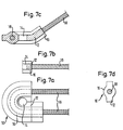
- FIGS. 7a, 7b, 7c and 7d shown according to a fourth embodiment, wherein in 7a shows a first variant which relates to the sectional view 7b, and in the lower half of FIG Figure 7a shows a second variant, on which the sectional view of Figure 7c relates.
- the tether loops 18 the bore 14, the tether 18 parallel with two sections emerges from each other from the fastening part 10.
- the fastening part 10 formed from a profile piece which is bent through 180 °, so that in the area enclosed by the tether 18 the fastening sheet 12 is formed, in which the bore 14 is made.
- the tether 18 emerges from the Fastening part 10 in the plane from the fastening sheet 12th is defined.
- free end of the holding section 16 relative to the plane by the Attachment sheet 12 is defined, angled so that the tether 18 emerges at an angle to this level.
- the one shown in these figures Embodiment is particularly advantageous if at the same time two buckles with a fastening point on Vehicle should be connected.
- FIGS. 8a, 8b and 8c shown according to a fifth embodiment.
- This Fastening part differs from the fastening part according to the fourth embodiment essentially in that the holding section 16 is angled by 90 ° so that the tether 18 is approximately vertical extends to the plane formed by the mounting sheet 12 is.
- Figure 8b is the mounting screw 24 and a Washer 26 can be seen with which the fastening part on the vehicle is screwed on.
- FIG. 9 shows a fastening part according to the invention in one Intermediate manufacturing step shown.
- an inexpensive Manufacturing will be done for forming the blank into the fastener preferably two contiguous blanks used, so that there are two connected fastening parts. These must just be separated from each other.
- FIG 10 is an inventive fastener in one represented another intermediate production step.
- This intermediate step consists of holding section 16 in a conical shape to transform as this according to the second embodiment of the invention is provided.
- the holding forces of the tether 18 in the holding portion 16 increased.
Landscapes
- Engineering & Computer Science (AREA)
- Mechanical Engineering (AREA)
- Automotive Seat Belt Assembly (AREA)
- Connection Of Plates (AREA)
- Clamps And Clips (AREA)
Abstract
Description
- die Figuren 1a, 1b und 1c in einer Draufsicht, Schnittansicht bzw. Seitenansicht ein erfindungsgemäßes Befestigungsteil gemäß einer ersten Ausführungsform;
- die Figuren 2a, 2b und 2c in einer Draufsicht, Schnittansicht bzw. Seitenansicht ein Befestigungsteil gemäß dem Stand der Technik;
- die Figuren 3a, 3b und 3c in einer Draufsicht, Schnittansicht bzw. Seitenansicht ein erfindungsgemäßes Befestigungsteil gemäß einer zweiten Ausführungsform;
- Figur 4 in einer Draufsicht eine Variante des Befestigungsteils von Figur 3a;
- Figur 5 in einer Draufsicht ein erfindungsgemäßes Befestigungsteil gemäß einer dritten Ausführungsform;
- die Figuren 6a und 6b in einer Draufsicht bzw. Seitenansicht eine Variante des Befestigungsteils von Figur 5;
- die Figuren 7a, 7b, 7c und 7d in einer Draufsicht, Schnittansicht bzw. Seitenansicht ein erfindungsgemäßes Befestigungsteil gemäß einer vierten Ausführungsform;
- die Figuren 8a, 8b und 8c in einer Draufsicht, Schnittansicht bzw. Seitenansicht ein erfindungsgemäßes Befestigungsteil gemäß einer fünften Ausführungsform;
- Figur 9 ein erfindungsgemäßes Befestigungsteil in einem Herstellungs-Zwischenschritt; und
- Figur 10 ein erfindungsgemäßes Befestigungsteil in einem weiteren Herstellungs-Zwischenschritt.
Claims (33)
- Befestigungsteil (10) für ein Halteseil (18) in einem Fahrzeug-Sicherheitsgurtsystem, mit einem Befestigungsblatt (12), das mit einer Bohrung (14) für eine Befestigungsschraube versehen ist, und einem Halteabschnitt (16), in den das Halteseil (18) eingepreßt ist, dadurch gekennzeichnet, daß das Befestigungsteil (10) aus Aluminium oder einer Aluminiumlegierung besteht.
- Befestigungsteil nach Anspruch 1, dadurch gekennzeichnet, daß das Befestigungsblatt (12) in der axialen Verlängerung des Halteabschnitts (16) angeordnet ist.
- Befestigungsteil nach Anspruch 2, dadurch gekennzeichnet, daß der Halteabschnitt (16), gemessen in der Richtung der Längsachse der Bohrung (14), etwa die gleiche Dicke wie das Befestigungsblatt (12) hat.
- Befestigungsteil nach Anspruch 2, dadurch gekennzeichnet, daß der Halteabschnitt (16), gemessen in der Richtung der Längsachse der Bohrung (14), eine größere Dicke als das Befestigungsblatt (12) hat.
- Befestigungsteil nach einem der Ansprüche 2 bis 4, dadurch gekennzeichnet, daß der Halteabschnitt (16) an seinem freien Ende, gemessen in einer Richtung senkrecht zur Längsachse der Bohrung (14) und senkrecht zur Längsachse des Halteseils (18), eine geringere Breite als an seinem Übergang zum Befestigungsblatt (12) hat.
- Befestigungsteil nach einem der Ansprüche 2 bis 4, dadurch gekennzeichnet, daß die Breite des Halteabschnittes (16) stufenartig etwa in dessen Mitte zunimmt.
- Befestigungsteil nach einem der Ansprüche 2 bis 4, dadurch gekennzeichnet, daß die Breite des Halteabschnittes (16) kontinuierlich von seinem freien Ende zu seinem Übergang in das Befestigungsblatt (12) hin zunimmt.
- Befestigungsteil nach einem der Ansprüche 2 bis 7, dadurch gekennzeichnet, daß die Breite des Befestigungsblattes (12) kontinuierlich von seinem Übergang in den Halteabschnitt (16) zu seinem freien Ende hin zunimmt.
- Befestigungsteil nach einem der Ansprüche 7 und 8, dadurch gekennzeichnet, daß der Winkel zwischen der Außenkante des Befestigungsteils (10), die in einer Ebene senkrecht zur Längsachse der Bohrung (14) liegt, und der Längsachse des in den Halteabschnitt (16) eingeschlossenen Halteseils (18) etwa 3,5° bis etwa 6° beträgt.
- Befestigungsteil nach einem der Ansprüche 2 bis 9, dadurch gekennzeichnet, daß sich das Halteseil (18) bis annähernd zu der Bohrung (14) hin erstreckt.
- Befestigungsteil nach Anspruch 1, dadurch gekennzeichnet, daß der Halteabschnitt (16) umlaufend um das Befestigungsblatt (12) ausgebildet ist, so daß das Halteseil (18) das Befestigungsblatt (12) umschlingt.
- Befestigungsteil nach Anspruch 11, dadurch gekennzeichnet, daß das Halteseil (18) aus dem Halteabschnitt (16) beiderseits des Befestigungsblattes (12) in zueinander parallelen Richtungen austritt.
- Befestigungsteil nach einem der Ansprüche 11 und 12, dadurch gekennzeichnet, daß das Befestigungsblatt (12), gemessen in der Richtung der Längsachse der Bohrung (14), eine geringere Dicke als der Halteabschnitt (16) hat.
- Befestigungsteil nach einem der Ansprüche 11 bis 13, dadurch gekennzeichnet, daß das freie Ende des Halteabschnittes (16) relativ zu der Ebene abgewinkelt ist, die von dem Befestigungsblatt (12) definiert ist.
- Befestigungsteil nach Anspruch 14, dadurch gekennzeichnet, daß der Halteabschnitt (16) um etwa 30° abgewinkelt ist.
- Befestigungsteil nach Anspruch 14, dadurch gekennzeichnet, daß der Halteabschnitt (16) um etwa 90° abgewinkelt ist.
- Befestigungsteil nach Anspruch 1, dadurch gekennzeichnet, daß das Befestigungsblatt (12) in der axialen Richtung des Halteseils (18) gesehen neben dem Halteabschnitt (16) angeordnet ist.
- Befestigungsteil nach Anspruch 17, dadurch gekennzeichnet, daß das Befestigungsblatt (12), gemessen in der Richtung der Längsachse der Bohrung (14), die gleiche Dicke wie der Halteabschnitt (16) hat.
- Befestigungsteil nach Anspruch 17, dadurch gekennzeichnet, daß das Befestigungsblatt (12), gemessen in der Richtung der Längsachse der Bohrung (14), eine geringere Dicke als der Halteabschnitt (16) hat.
- Befestigungsteil nach einem der Ansprüche 17 bis 19, dadurch gekennzeichnet, daß das Halteseil (18) mit seinem freien Ende aus dem Halteabschnitt (16) austritt.
- Befestigungsteil nach einem der Ansprüche 17 bis 20, dadurch gekennzeichnet, daß in dem Befestigungsblatt (12) neben der Bohrung (14) ein Schlitz (20) zur Befestigung einer Gurtbandschlaufe (22) gebildet ist.
- Befestigungsteil nach einem der vorhergehenden Ansprüche, dadurch gekennzeichnet, daß es aus einem mit einer Öffnung für das Halteseil (18) versehenen Rohling gebildet ist.
- Befestigungsteil nach Anspruch 22, dadurch gekennzeichnet, daß der Rohling eine buchsenförmige Gestalt hat.
- Befestigungsteil nach Anspruch 22, dadurch gekennzeichnet, daß der Rohling ein Profilteil ist.
- Befestigungsteil nach einem der vorhergehenden Ansprüche, dadurch gekennzeichnet, daß das Befestigungsblatt (12) durch Pressen des Rohlings gebildet ist.
- Befestigungsteil nach einem der vorhergehenden Ansprüche, dadurch gekennzeichnet, daß der Halteabschnitt (16) durch Pressen des Rohlings gebildet ist und das Halteseil (18) vor dem Pressen in den Rohling eingelegt wurde.
- Befestigungsteil nach einem der vorhergehenden Ansprüche, dadurch gekennzeichnet, daß der Rohling eine allgemein zylindrische Form hat und das Befestigungsblatt (12) durch Flachpressen eines axialen Endes des Rohling gebildet ist.
- Befestigungsteil nach einem der vorhergehenden Ansprüche, dadurch gekennzeichnet, daß die Bohrung (14) durch Aufweiten eines Lochs gebildet ist, das kleinere Abmessungen als die Bohrung (14) hat.
- Befestigungsteil nach einem der vorhergehenden Ansprüche, dadurch gekennzeichnet, daß dessen Material kaltverfestigt ist.
- Befestigungsteil nach einem der vorhergehenden Ansprüche, dadurch gekennzeichnet, daß ein Material der Festigkeitsklassen F25 bis F55 verwendet wird.
- Befestigungsteil nach einem der vorhergehenden Ansprüche, dadurch gekennzeichnet, daß das Halteseil (18) aus Stahl besteht.
- Befestigungsteil nach Anspruch 31, dadurch gekennzeichnet, daß das Halteseil (18) einen Durchmesser von maximal 5,8 mm hat.
- Befestigungsteil nach einem der vorhergehenden Ansprüche, dadurch gekennzeichnet, daß es durch Trennen von zwei identischen Befestigungsteilen (10) gebildet ist, die nach dem Pressen einstückig miteinander verbunden sind.
Applications Claiming Priority (6)
| Application Number | Priority Date | Filing Date | Title |
|---|---|---|---|
| DE19627202 | 1996-07-05 | ||
| DE1996127202 DE19627202A1 (de) | 1996-07-05 | 1996-07-05 | Verfahren zum Herstellen eines Lochs in Metallblechteilen für Fahrzeuginsassen-Rückhaltesysteme |
| DE19638441 | 1996-09-19 | ||
| DE19638441A DE19638441A1 (de) | 1996-09-19 | 1996-09-19 | Verfahren zum Herstellen von Preßteilen für Fahrzeuginsassen-Rückhaltesysteme |
| DE29704021U | 1997-03-05 | ||
| DE29704021U DE29704021U1 (de) | 1996-07-05 | 1997-03-05 | Befestigungsteil für ein Halteseil in einem Fahrzeug-Sicherheitsgurtsystem |
Publications (2)
| Publication Number | Publication Date |
|---|---|
| EP0818370A2 true EP0818370A2 (de) | 1998-01-14 |
| EP0818370A3 EP0818370A3 (de) | 2000-09-27 |
Family
ID=27216430
Family Applications (1)
| Application Number | Title | Priority Date | Filing Date |
|---|---|---|---|
| EP97111299A Withdrawn EP0818370A3 (de) | 1996-07-05 | 1997-07-04 | Befestigungsteil für ein Halteseil in einem Fahrzeug-Sicherheitsgurtsystem |
Country Status (3)
| Country | Link |
|---|---|
| EP (1) | EP0818370A3 (de) |
| JP (1) | JPH1095307A (de) |
| ES (1) | ES2112231T1 (de) |
Family Cites Families (7)
| Publication number | Priority date | Publication date | Assignee | Title |
|---|---|---|---|---|
| GB1242150A (en) * | 1969-03-20 | 1971-08-11 | Wingard Ltd | Improvements relating to safety seat belts for vehicles |
| GB1304055A (de) * | 1970-06-09 | 1973-01-24 | ||
| CA1077243A (en) * | 1976-12-20 | 1980-05-13 | Dante Tettamanti | Turn-back loop for wire strands |
| US4194786A (en) * | 1977-11-29 | 1980-03-25 | Acco Industries Inc. | Safety belt anchorage assembly |
| GB2252571A (en) * | 1991-01-18 | 1992-08-12 | Ccl Systems Ltd | Attaching terminal to wire rope |
| US5141352A (en) * | 1991-01-31 | 1992-08-25 | Header Products, Inc. | Seat belt anchor |
| DE9303276U1 (de) * | 1993-03-06 | 1993-04-22 | TRW Repa GmbH, 7077 Alfdorf | Gurtstraffer in einem Sicherheitsgurtsystem für Fahrzeuge |
-
1997
- 1997-07-04 JP JP17875897A patent/JPH1095307A/ja active Pending
- 1997-07-04 ES ES97111299T patent/ES2112231T1/es active Pending
- 1997-07-04 EP EP97111299A patent/EP0818370A3/de not_active Withdrawn
Also Published As
| Publication number | Publication date |
|---|---|
| JPH1095307A (ja) | 1998-04-14 |
| EP0818370A3 (de) | 2000-09-27 |
| ES2112231T1 (es) | 1998-04-01 |
| MX9705067A (es) | 1998-05-31 |
Similar Documents
| Publication | Publication Date | Title |
|---|---|---|
| EP0599026B1 (de) | Spreizanker aus Metall | |
| DE2907360C2 (de) | Gewindeformende Schraube und Rohling zu deren Herstellung | |
| DE69211248T2 (de) | Hochleistungs-Blindboltzen mit gleicher Greifkraft über einen erweiterten Greifbereich | |
| DE69722818T2 (de) | Blindniet und verfahren zu seiner herstellung | |
| DE60125768T2 (de) | Gewalzter und gestanzter türträger | |
| DE3035867A1 (de) | Selbstverstopfender blindniet | |
| DE4009690A1 (de) | Verfahren und vorrichtung zum herstellen von ankerschrauben fuer beton | |
| EP0894986A2 (de) | Blindniet | |
| DE3601968A1 (de) | Verriegelungselement fuer eine schliessvorrichtung | |
| DE68907341T2 (de) | Befestigungssystem und befestigung zum versand von behältern und sonstigem. | |
| DE69210518T2 (de) | Befestigungseinrichtung für vorgebohrte Glasscheiben | |
| DE2308808A1 (de) | Blindniet | |
| DE3300676C2 (de) | ||
| DE69501672T2 (de) | Blindniete | |
| DE4034862C2 (de) | ||
| EP3366384B1 (de) | Verfahren zum herstellen eines blindniets, blindniet und befestigungsanordnung | |
| EP1064466A1 (de) | Stanzniet | |
| EP1181461B1 (de) | Blindniet für Bauteile unterschiedlicher Wandstärke und Verfahren zum Herstellen eines solchen Blindniets | |
| DE3329047A1 (de) | Huelse fuer einen ankerbolzen und verfahren zum herstellen einer solchen huelse | |
| DE10210781B4 (de) | Befestigungsmittel für einen Sicherheitsgurt | |
| EP0818370A2 (de) | Befestigungsteil für ein Halteseil in einem Fahrzeug-Sicherheitsgurtsystem | |
| DE69617353T2 (de) | Blindniet | |
| EP0292734A1 (de) | Gewindeformende Schraube | |
| EP0757185A1 (de) | Schlaganker | |
| DE29704021U1 (de) | Befestigungsteil für ein Halteseil in einem Fahrzeug-Sicherheitsgurtsystem |
Legal Events
| Date | Code | Title | Description |
|---|---|---|---|
| PUAI | Public reference made under article 153(3) epc to a published international application that has entered the european phase |
Free format text: ORIGINAL CODE: 0009012 |
|
| AK | Designated contracting states |
Kind code of ref document: A2 Designated state(s): DE ES FR GB IT |
|
| ITCL | It: translation for ep claims filed |
Representative=s name: DR. ING. A. RACHELI & C. |
|
| GBC | Gb: translation of claims filed (gb section 78(7)/1977) | ||
| REG | Reference to a national code |
Ref country code: ES Ref legal event code: BA2A Ref document number: 2112231 Country of ref document: ES Kind code of ref document: T1 |
|
| EL | Fr: translation of claims filed | ||
| RAP1 | Party data changed (applicant data changed or rights of an application transferred) |
Owner name: TRW OCCUPANT RESTRAINT SYSTEMS GMBH & CO. KG |
|
| PUAL | Search report despatched |
Free format text: ORIGINAL CODE: 0009013 |
|
| AK | Designated contracting states |
Kind code of ref document: A3 Designated state(s): AT BE CH DE DK ES FI FR GB GR IE IT LI LU MC NL PT SE |
|
| 17P | Request for examination filed |
Effective date: 20010214 |
|
| AKX | Designation fees paid |
Free format text: DE ES FR GB IT |
|
| 17Q | First examination report despatched |
Effective date: 20021126 |
|
| STAA | Information on the status of an ep patent application or granted ep patent |
Free format text: STATUS: THE APPLICATION IS DEEMED TO BE WITHDRAWN |
|
| 18D | Application deemed to be withdrawn |
Effective date: 20030607 |