EP0818372B1 - System für die Antriebs- und Bremssteuerung eines Schienenfahrzeuges - Google Patents
System für die Antriebs- und Bremssteuerung eines Schienenfahrzeuges Download PDFInfo
- Publication number
- EP0818372B1 EP0818372B1 EP97111295A EP97111295A EP0818372B1 EP 0818372 B1 EP0818372 B1 EP 0818372B1 EP 97111295 A EP97111295 A EP 97111295A EP 97111295 A EP97111295 A EP 97111295A EP 0818372 B1 EP0818372 B1 EP 0818372B1
- Authority
- EP
- European Patent Office
- Prior art keywords
- wheel
- wheel load
- nominal value
- manipulated variable
- slip
- Prior art date
- Legal status (The legal status is an assumption and is not a legal conclusion. Google has not performed a legal analysis and makes no representation as to the accuracy of the status listed.)
- Expired - Lifetime
Links
- 238000005259 measurement Methods 0.000 claims description 11
- 230000008859 change Effects 0.000 claims description 9
- 230000000670 limiting effect Effects 0.000 claims description 8
- 230000009467 reduction Effects 0.000 claims description 8
- 230000015572 biosynthetic process Effects 0.000 claims description 3
- 230000001419 dependent effect Effects 0.000 claims description 3
- 238000001514 detection method Methods 0.000 claims 2
- 230000035882 stress Effects 0.000 description 37
- 238000013461 design Methods 0.000 description 4
- 238000000034 method Methods 0.000 description 4
- 239000000463 material Substances 0.000 description 3
- 230000036961 partial effect Effects 0.000 description 3
- 230000007704 transition Effects 0.000 description 3
- 230000001133 acceleration Effects 0.000 description 2
- 230000000694 effects Effects 0.000 description 2
- 230000012447 hatching Effects 0.000 description 2
- 230000002829 reductive effect Effects 0.000 description 2
- 230000001105 regulatory effect Effects 0.000 description 2
- 239000012080 ambient air Substances 0.000 description 1
- 238000013459 approach Methods 0.000 description 1
- 230000008094 contradictory effect Effects 0.000 description 1
- 230000003247 decreasing effect Effects 0.000 description 1
- 238000010438 heat treatment Methods 0.000 description 1
- 230000006872 improvement Effects 0.000 description 1
- 238000011835 investigation Methods 0.000 description 1
- 230000003137 locomotive effect Effects 0.000 description 1
- 230000007257 malfunction Effects 0.000 description 1
- 238000002844 melting Methods 0.000 description 1
- 230000008018 melting Effects 0.000 description 1
- 230000002093 peripheral effect Effects 0.000 description 1
- 230000008569 process Effects 0.000 description 1
- 230000008961 swelling Effects 0.000 description 1
- 230000008646 thermal stress Effects 0.000 description 1
- 238000011144 upstream manufacturing Methods 0.000 description 1
Images


Classifications
-
- B—PERFORMING OPERATIONS; TRANSPORTING
- B60—VEHICLES IN GENERAL
- B60T—VEHICLE BRAKE CONTROL SYSTEMS OR PARTS THEREOF; BRAKE CONTROL SYSTEMS OR PARTS THEREOF, IN GENERAL; ARRANGEMENT OF BRAKING ELEMENTS ON VEHICLES IN GENERAL; PORTABLE DEVICES FOR PREVENTING UNWANTED MOVEMENT OF VEHICLES; VEHICLE MODIFICATIONS TO FACILITATE COOLING OF BRAKES
- B60T8/00—Arrangements for adjusting wheel-braking force to meet varying vehicular or ground-surface conditions, e.g. limiting or varying distribution of braking force
- B60T8/17—Using electrical or electronic regulation means to control braking
- B60T8/1701—Braking or traction control means specially adapted for particular types of vehicles
- B60T8/1705—Braking or traction control means specially adapted for particular types of vehicles for rail vehicles
-
- B—PERFORMING OPERATIONS; TRANSPORTING
- B60—VEHICLES IN GENERAL
- B60L—PROPULSION OF ELECTRICALLY-PROPELLED VEHICLES; SUPPLYING ELECTRIC POWER FOR AUXILIARY EQUIPMENT OF ELECTRICALLY-PROPELLED VEHICLES; ELECTRODYNAMIC BRAKE SYSTEMS FOR VEHICLES IN GENERAL; MAGNETIC SUSPENSION OR LEVITATION FOR VEHICLES; MONITORING OPERATING VARIABLES OF ELECTRICALLY-PROPELLED VEHICLES; ELECTRIC SAFETY DEVICES FOR ELECTRICALLY-PROPELLED VEHICLES
- B60L2200/00—Type of vehicles
- B60L2200/26—Rail vehicles
Definitions
- the invention relates to a system for the drive and Brake control of a rail vehicle according to the preamble of Claim 1.
- Such a system for the drive and brake control of a Rail vehicle is known from DE 43 33 281 A1.
- the wheels of a rail-bound vehicle are subject to many Stresses. Analogous to the partial functions of the wheel, namely carrying, Leading and driving or braking can be related Partial stresses can be distinguished. With the sub-functions Wear and Perform essentially mechanical stresses that occur in the Design of the drive are sufficiently well known, so that usually sufficient through careful constructive design and choice of materials Security against overuse is guaranteed.
- the thermal stress on the wheel essentially results from two Swelling, the slip performance in the wheel / rail contact zone and with block braked Wheels from the heat input of the brake pads.
- the slip performance results from the product of tangential force and slip speed, it is assumed that the directions of these two quantities always match exactly.
- the hatching speed is the product from wheel slip and driving speed, with influences from vibrations are negligible in the chassis in the first approximation.
- the heat input through slip performance is distributed over the wheel and the rail, intermediate layers between the wheel and rail are added to the rail.
- the amount of heat supplied is essentially by convection released the ambient air.
- the amounts of heat dissipated are from Ambient temperature and especially depending on the driving speed. in the stationary state there is a certain heat distribution between Wheel and rail as well as a typical temperature distribution within the wheel and in the rail.
- the heat input from a block brake results from the tangential forces of the Brake pads and the circumferential wheel speed.
- the for the melting of The amount of heat absorbed by the brake pad material is added to the brake pad.
- In the steady state there is also a certain heat distribution between wheel and brake pad as well as a typical temperature distribution inside the wheel.
- the heat input by a block brake can be experimentally sufficient, at least determine exactly. This can be done with a tailored design the brake system, structural design of the wheel and suitable material selection achieved a certain level of security against overloading the wheel become. However, malfunctions in the brake system, for example fixed Braking, uneven distribution of braking on the train, long downhill braking even then excessive stresses on the wheels occur.
- the heat input is through a block brake not freely selectable because of safety-related concerns. So can although the amount of heat input is reduced by reducing the braking effect be, however, to maintain a predetermined braking distance Reduction is out of the question.
- the heat input through slip performance is essentially from the adhesion and Wheel slip behavior determined.
- the height of the respective frictional connection wheel / rail is influenced by a variety of influences and can therefore vary within wide limits and is practically not predictable.
- the wheel slip behavior is determined by the Non-positive connection and, if available, determined by a wheel slip control device.
- heat input can occur through slip performance be influenced by the respective wheel slip.
- wheel slip By reducing the slipping speed wheel slip can also be reduced. If so that a reduction of the transferable tangential force is connected this only for safety-relevant braking by means of special measurements on compliance the maximum braking distance extensions applicable in this regard are checked and be secured.
- the object underlying the invention is therefore a system for determining and specifying suitable control values for the drive and brake control specify a rail vehicle that protects the wheels against thermal and protects mechanical stresses that arise specifically from the heat input result from slip performance.
- wheel slip control devices In previously known vehicles, this task is accomplished, if at all, by Sub-functions of the wheel slip control device are perceived.
- the main task wheel slip control devices consists in reducing the wheel slip to one limit the specified value or set such a wheel slip, where the greatest possible adhesion is expected.
- Other additional functions may consist of the occurrence of natural vibrations in the drive train recognize and, if necessary, avoid them with a suitable wheel slip guide or actively dampen, for example, by modulating the drive torque. These measures are important for the protection of torque transmitting Structure of the drive systems.
- a closed control loop is used and in order to record the actual wheel load, the controller is informed of this Suitable measuring variables supplied control loop.
- the maximum values formed are not uniform for all operating conditions, but based on measured variables, which capture the current individual operating conditions. On in this way it is detected, for example, that the heat input due to wheel slip increases a temperature distribution that greatly depends on the peripheral speed of the Wheel is dependent. At high speed, the temperature is along the wheel circumference more evenly distributed than at low speed at which the heating quasi selectively.
- the heat input that can be borne without damage is a function of the speed.
- the slip control of a locomotive is thereby expanded by the slip control takes over the function of an actuator to which a suitable slip setpoint is to be specified.
- the wheel load limiter can even in cases of low friction can be used advantageously to exhaust to specify the maximum permissible wheel slip for the additional limit stress, in order to achieve the greatest possible traction in this way. To this In this way, effective protection of the wheels is provided on the one hand, and on the other hand at the same time achieved the greatest possible use of adhesion.
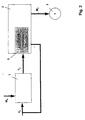
- a wheel load limiter 1 shows a system with a device for limiting the wheel load.
- the drive or brake control 2 accordingly specifies a drive or braking torque M d for a driven or braked wheel 3 (or for several wheels) of the rail vehicle.
- Measured variables X b for detecting the wheel stress are present as input signals to the wheel stress limiter 1, which are formed, for example, as actual values from sensors 4 for measuring wheel stress variables.
- the wheel load limiter 1 is supplied with limit values W b for the permissible wheel load.
- measurement variables X b for defining the wheel stresses are defined by specifying wheel stress criteria and that the drive or brake control 2 of the vehicle has manipulated variables, which meet a controllability condition, which means that in the event of significant changes in the manipulated variables, the change direction of the manipulated variable is uniquely assigned to the change direction of the wheel load, this assignment being valid for all working points with a non-zero wheel slip, while for negligibly small changes in the manipulated variables Wheel load with any direction of change, but can only change by negligibly small amounts.
- measured variables X b for describing the wheel load are available on the vehicle, that a wheel load limiter 1 has one or more inputs for these measured variables X b , with which the wheel load is detected that limit values W associated with the measured variables X b b are specified and that the wheel load limiter 1 has a controller (see number 10 in FIG. 5) of any type which limits the wheel load to the predetermined limit values W b and which forms the manipulated variables Y b which are used to control the drive or Brake control 2 are required.
- the measured variables X b for detecting the wheel load can be taken from the drive or brake control 2 itself or are formed directly as actual values from sensors 4.
- sensors 4 for measuring the wheel load can be used as sensors 4 for measuring the wheel tread surface temperature.
- any combination of the following signals can be used to form measured variables X b for describing the wheel load: tread temperature, traction or braking force, wheel slip speed, percentage wheel slip, wheel traction power, wheel slip due to friction, on the circumferential wheel speed or driving speed-related slip-related friction of the wheel.
- These signals can only be used by one wheel or by several selected wheels or by all wheels of the vehicle.
- the aim is to completely or at least partially dispense with additional sensors 4. Then it is necessary to estimate one or more measured variables X b by an observer - replica in a model that depicts the physically relevant processes and accordingly forms the measured variable - whereby instead of the measured variables detected by sensors 4, other measured variables are supplied to the wheel stress limiter 1 ,
- the measurands supplied to the observer must be selected so that the condition of observability is fulfilled for the stress measurand that is to be estimated by the observer.
- the tread temperature in the contact zone can be determined by an observer are estimated, the current driving speed as measured variables, the supplied heat output and the ambient temperature are supplied.
- the limit values W b for the permissible wheel load are not always specified in the form of constant values. Instead, they can, for example, be functions of temperature, driving speed or the effectiveness of an existing block brake. In other words, one or more limit values W b for the wheel load can be functions of measured variables or variables derived therefrom.
- the wheel load is essentially determined by the slip performance.
- the slip performance the slip speed or the percent wheel slip meet the above controllability condition. It is therefore advisable to use the control variable Y b for the. Use a setpoint for the slip speed or the percentage wheel slip.
- This manipulated variable can then be connected to a related input of the wheel slip control (see number 5 in FIG. 2), which in this context is regarded as a component of the drive or brake control 2.
- Well-known wheel slip control devices often contain their own setpoint devices to specify the slip speed or the percentage Wheel slip with a view to achieving the greatest possible adhesion.
- Such a setpoint generator can e.g. through a procedure for independent investigation of optimal wheel slip.
- the device according to the invention to limit the wheel load also provides such a setpoint device represents.
- One of the setpoints Y b or Y 2 is switched through by channels 13, 14 via an output stage 15 as the active manipulated variable Y, ie as the setpoint for the wheel slip control 5.
- FIG. 3 shows an example of a variant with only two channels with regard to manipulated variable transmitters 6 and manipulated variable selection 9, however, in addition to the two setpoint generators 1, 8 there are other setpoint transmitters, the outputs of which are occasional are to be connected to the setpoint input of the wheel slip control 5, wherein the setpoint selection is made by the manipulated variable selection 9, which is the required one Number of channels with one input each from one of the channels to be forwarded on a case-by-case basis Setpoints and a common output for the to be passed on Has setpoint.
- the largest setpoint is selected and switched through for all setpoints Y b , Y 2 ... in accordance with the maximum value principle, if a reduction in the wheel load is assigned in the sense of the controllability condition, and it is based on the minimum value principle the smallest setpoint is selected and switched through if a reduction in the wheel load is assigned to the negative setpoint change in the sense of the controllability condition.
- the target value for the slip speed or for the percentage wheel slip meets the controllability condition in such a way that a positive change in the Setpoint results in a positive change in the wheel load. Therefore In this case it is expedient to use the minimum value principle as a method for selecting the setpoint use.
- the manipulated variable selection 9 preferably additionally has one or more outputs, via the binary feedback signals (see M 1 , M 2 in FIG. 4) for identifying the currently selected channel and / or via which the value of the setpoint switched through is fed back to the various setpoint generators become.
- the setpoint formation is preferably carried out within at least one setpoint generator, depending on whether the setpoint output has been switched through by the manipulated variable selection 9 or not.
- the setpoint formation is preferably carried out in at least one setpoint generator 1, 8 in such a way that when the command value selection 9 is not switched through, the setpoint is set to the minimum allowable setpoint if at Channel selection the maximum value principle is applied and to the maximum permissible Setpoint is set if the minimum value principle is used for channel selection is applied.
- the manipulated variable selection 9 additionally has one or more inputs for the following signal types for channel selection: an input for specifying the number of the channel to be switched through (channel number input) and / or inputs for binary request signals (see A 1 , A 2 in FIG. 4), each assigned to a specific channel.
- the channel determined by this number is switched through. Is not a channel number specified, the channel is selected in accordance with the binary request signals, the query of the binary request signals for channel selection in order decreasing priority, so that when there is at least one Request signal from the requested channels the one with the highest Priority is selected. Otherwise the channel is selected according to the minimum value or maximum value principle.
- the channels for the setpoints for limiting the wheel load are preferred assigned a higher priority than the other channels.
- the binary request signals are for one or more channels issued by the associated setpoint devices 1, 8.
- the setpoint generator 1 for limiting the wheel load it applies that it is part of a closed control loop when the setpoint value formed by it affects the wheel slip control 5 from the control variable selection 9.
- the setpoint Y 2 for setting the optimal slip can be lower than the setpoint Y b for limiting the wheel load. Then, according to the minimum value principle, the target value Y 2 is switched through and the control circuit for limiting the wheel load with the wheel load limiter 1 is cut open. If the controller of the wheel stress limiter 1 has an integrating component in a control characteristic, the setpoint Y b will then reach the upper manipulated variable limit after some time.
- the Radbe tapeungsbegrenzer 1 can not immediately accept the specification of the desired value for the wheel slip 5, but only there elapses a time until the desired value Y b is smaller than the target value Y. 2 The wheel is not protected against excessive stress during this period.
- the setpoint generator 1 emits a binary request signal A 1 “request first channel” to channel 13, while channel 13 additionally outputs a binary feedback signal M 1 “first channel active” to identify the switched state of the channel to setpoint generator 1.
- the setpoint generator 8 gives in addition to the setpoint Y 2 a binary request signal A 2 "request second channel” to the channel 14, while the channel 14 additionally a binary feedback signal M 2 "second channel active” to identify the switched state of the Outputs channel to the setpoint generator 8.
- the currently active manipulated variable Y is supplied to the wheel slip control 5 and to both setpoint transmitters 1, 8 of the manipulated variable transmitter 6.
- the channel 13 is assigned a higher priority than the channel 14. Then, when both request signals A 1 , A 2 are present, channel 13 is switched through; if only one request signal A 1 or A 2 is active, if the relevant channel is selected, there is no request signal, the selection is made according to the minimum value principle.
- the wheel stress limiter 1 has a wheel stress regulator 10 with an upstream subtraction point 7, a channel request 11, a selection switch 12 and an OR gate 16.
- the feedback signal M 1 and the currently active manipulated variable Y are also applied to the wheel stress controller 10 on the input side.
- the wheel stress controller 10 forms a manipulated variable Y r (depending on R b , M 1 and Y) as the controller output signal and forwards it to the first input of the selection switch 12.
- the second input of the selector switch 12 has a substitute setpoint Y def for the setpoint to be output in the case of the open-loop control circuit (if the manipulated variable selection 9 does not switch through the manipulated variable Y b ).
- the selection switch 12 On the output side, the selection switch 12 outputs either Y r or Y def as the manipulated variable.
- the selection switch 12 is actuated by the OR gate 16 - M1 and A1 are present on the input side and which controls the selection switch 12 on the output side - whenever the request signal A 1 and / or the feedback signal M 1 is active. When the control is active, the selection switch 12 switches through the controller output signal Y R.
- the feedback signal M 1 keeps the controller output signal Y r of the wheel load controller 10 at the value of the active setpoint Y. If the wheel load state defined by R b is not critical, the substitute setpoint Y def is forwarded as manipulated variable Y b by the selector switch 12.
- the value of the upper manipulated variable limit (maximum permissible setpoint) is expediently used as the value of Y def , so that Y b is not selected according to the minimum value principle.
- the wheel stress reserve R b approaches zero, the wheel stress becomes critical.
- the channel request 11 then uses the request signal A 1 to make a request for setpoint switching.
- the controller output signal Y R is now forwarded as manipulated variable Y b by the selector switch 12. Due to the initialization of the wheel stress controller 10 still carried out at this point in time, the manipulated variable Y b has the same value as the currently active manipulated variable Y.
- the transition takes place between another target value, for example, Y 2 and the target value Y b of the Radbe pipeungsbegrenzers 1 continuously, ie without a step in the course of the active manipulated variable Y. Since on the feedback signal M 1 is now the output target value Y b is actively reported (the control circuit with the Radbe bulkungsbegrenzer 1 is closed) , the initialization state of the wheel stress controller 10 is canceled and the controller 10 can work freely. In this way, the control for protection against overload can be effective immediately when the wheel load condition becomes critical.
- the controller output signal Y R is switched through by the selection switch 12 as a function of the feedback signal M 1 , until another command channel is finally activated by requesting another channel or in accordance with the minimum value principle, and thus the feedback signal M 1 also becomes inactive.
- dispensable Criterion during normal operational use of the vehicle waived (dispensable criterion), and this dispensable Criterion is replaced by at least one other, always effective criterion (Replacement criterion), whose stress measurement is always available. Compliance
- the limit of the dispensable criterion is determined by a suitable choice the limit values for the replacement criteria are reached and by measurements on the vehicle demonstrated by the wheel stress measurement of the dispensable criterion measured by temporarily installed sensors and with the respective permissible wheel load is compared.
Landscapes
- Engineering & Computer Science (AREA)
- Transportation (AREA)
- Mechanical Engineering (AREA)
- Regulating Braking Force (AREA)
- Train Traffic Observation, Control, And Security (AREA)
- Hydraulic Control Valves For Brake Systems (AREA)
- Electric Propulsion And Braking For Vehicles (AREA)
Description
- Fig. 1
- ein System mit Einrichtung zur Begrenzung der Radbeanspruchung,
- Fig. 2
- ein System mit Zuführung der Stellgröße an die Radschlupfregelung,
- Fig. 3
- ein System mit zusätzlicher Stellgrößenauswahl,
- Fig. 4
- ein System mit zusätzlichen Anforderungs- und Rückmeldungssignalen,
- Fig. 5
- die Signalführung innerhalb eines Sollwertgebers am Beispiel des Radbeanspruchungsbegrenzers.
Claims (14)
- System zur Ermittlung und Vorgabe geeigneter Stellgrößen für die Antriebs- und Bremsensteuerung eines Schienenfahrzeuges unter Einsatz einer Antriebs- bzw. Bremsensteuerung (2) mit Radschlupfregelung (5), deren Stellgröße von mindestens einem ersten Sollwertgeber (8) vorgegeben wird, dadurch gekennzeichnet,dass ein Radbeanspruchungsbegrenzer (1) mit einem Radbeanspruchungsregler (10) vorgesehen ist, wobei dem Radbeanspruchungsbegrenzer (1) eingangsseitig mindestens eine Messgröße (Xb) zur Erfassung der Radbeanspruchung sowie mindestens ein Grenzwert (Wb) für die zulässige Radbeanspruchung zuleitbar sind und der Radbeanspruchungsregler (10) die Radbeanspruchung auf den mindestens einen Grenzwert begrenzt und eine weitere Stellgröße (Y, Yb, YR) zur Beeinflussung der Antriebs- und Bremsensteuerung (2) bildet unddass eine Stellgrößenauswahl (9) mit mindestens zwei Kanälen (13, 14) vorgesehen ist, die eingangsseitig außer dem Sollwert des Radbeanspruchungsbegrenzers (1) mindestens einen weiteren Sollwert des mindestens einen ersten Sollwertgebers (8) zur optimalen Einstellung des Radschlupfes empfängt, eine Sollwert-Auswahl vornimmt und ausgangsseitig den ausgewählten Sollwert an die Radschlupfregelung (5) abgibt.
- System nach Anspruch 1, dadurch gekennzeichnet, dass mindestens eine Messgröße (Xb) zur Erfassung der Radbeanspruchung durch einen Sensor (4) gebildet wird.
- System nach Anspruch 1, dadurch gekennzeichnet, dass mindestens eine Messgröße (Xb) zur Erfassung der Radbeanspruchung durch einen Beobachter geschätzt wird, welcher eine Beobachtung der Radbeanspruchung gewährleistet.
- System nach mindestens einem der vorstehenden Ansprüche 1 bis 3, dadurch gekennzeichnet, dass als Messgröße (Xb) die Temperatur der Radlauffläche und/oder die Zug- bzw. Bremskraft und/ oder die Schlupfgeschwindigkeit und/oder der prozentuale Schlupf und/oder die Traktionsleistung und/oder die schlupfbedingte Reibleistung und/oder die auf die Radumfangsgeschwindigkeit bzw. Fahrgeschwindigkeit bezogene schlupfbedingte Reibleistung herangezogen wird.
- System nach mindestens einem der vorstehenden Ansprüche 1 bis 4, dadurch gekennzeichnet, dass mindestens ein Grenzwert (Wb) für die zulässige Radbeanspruchung eine Funktion einer weiteren Messgröße (Xb) oder eine davon abgeleitete Größe ist.
- System nach mindestens einem der vorstehenden Ansprüche 1 bis 5, dadurch gekennzeichnet, dass die Stellgrößenauswahl (9) Rückmeldesignale (M1, M2) zur Rückmeldung des Kanals (13, 14) des aktuell an die Radschlupfregelung (5) durchgeschalteten Sollwerts an den Radbeanspruchungsbegrenzer (1) und den mindestens einen ersten Sollwertgeber (8) abgibt.
- System nach Anspruch 6, dadurch gekennzeichnet, dass der Wert des aktuell an die Radschlupfregelung (5) durchgeschalteten Sollwerts an den Radbeanspruchungsbegrenzer (1) und den mindestens einen ersten Sollwertgeber (8) rückgemeldet wird.
- System nach Anspruch 6 oder 7, dadurch gekennzeichnet, dass die Sollwertbildung innerhalb des Radbeanspruchungsbegrenzers (1) oder des mindestens einen ersten Sollwertgebers (8) in Abhängigkeit davon erfolgt, ob der vorgegebene Sollwert von der Stellgrößenauswaht (9) durchgeschaltet worden ist.
- System nach mindestens einem der Ansprüche 6 bis 8, dadurch gekennzeichnet, dass der Radbeanspruchungsbegrenzer (1) und/oder der mindestens eine erste Sollwertgeber (8) Anforderungssignale (A1, A2) an die Stellgrößenauswahl (9) abgeben, den vorgegebenen Sollwert durchzuschalten.
- System nach Anspruch 9, dadurch gekennzeichnet, dass ein Anforderungssignal (A1, A2) abgegeben wird, wenn sich durch Vergleich der zulässigen Radbeanspruchung mit der durch mindestens eine Messgröße erfassten Radbeanspruchung ein kritischer Radbeanspruchungszustand ergibt.
- System nach mindestens einem der Ansprüche 6 bis 10, dadurch gekennzeichnet, dass die Stellgrößenauswahl (9) gemäß dem Maximalwert-Prinzip den größten der vorgegebenen Sollwerte auswählt und durchschaltet, wenn eine positive Sollwertänderung eine Verringerung der Radbeanspruchung zur Folge hat und dass die Stellgrößenauswahl (9) gemäß dem Minimalwert-Prinzip den kleinsten der vorgegebenen Sollwerte auswählt und durchschaltet, wenn eine negative Sollwertänderung eine Verringerung der Radbeanspruchung zur Folge hat.
- System nach Anspruch 11, dadurch gekennzeichnet, dass bei nicht von der Stellgrößenauswahl (9) durchgeschaltetem Sollwert der Radbeanspruchungsbegrenzer (1) und/oder der mindestens eine erste Sollwertgeber (8) auf den minimal zulässigen Sollwert gesetzt werden, wenn bei der Auswahl der Stellgrößenauswahl (9) das Maximalwert-Prinzip angewendet wird und auf den maximal zulässigen Sollwert gesetzt werden, wenn bei der Auswahl der Stellgrößenauswahl (9) das Minimalwert-Prinzip angewendet wird.
- System nach mindestens einem der Ansprüche 6 bis 12, dadurch gekennzeichnet, dass die Stellgrößenauswahl (9) den Kanal (13, 14) auswählt, für den ein Anforderungssignal (A1, A2) vorliegt, wobei den Kanälen Prioritäten zugeordnet sind und die Sollwerte zur Begrenzung der Radbeanspruchung eine höhere Priorität aufweisen als die weiteren Sollwerte.
- System nach Anspruch 13, dadurch gekennzeichnet, dass die Stellgrößenauswahl (9) gemäß dem Maximalwert-Prinzip oder Minimalwert-Prinzip den Kanal (13, 14) auswählt, wenn kein Anforderungssignal (A1, A2) vorliegt.
Applications Claiming Priority (2)
| Application Number | Priority Date | Filing Date | Title |
|---|---|---|---|
| DE19627731A DE19627731A1 (de) | 1996-07-10 | 1996-07-10 | System für die Antriebs- und Bremsensteuerung eines Schienenfahrzeuges |
| DE19627731 | 1996-07-10 |
Publications (3)
| Publication Number | Publication Date |
|---|---|
| EP0818372A2 EP0818372A2 (de) | 1998-01-14 |
| EP0818372A3 EP0818372A3 (de) | 2000-07-05 |
| EP0818372B1 true EP0818372B1 (de) | 2002-10-23 |
Family
ID=7799401
Family Applications (1)
| Application Number | Title | Priority Date | Filing Date |
|---|---|---|---|
| EP97111295A Expired - Lifetime EP0818372B1 (de) | 1996-07-10 | 1997-07-04 | System für die Antriebs- und Bremssteuerung eines Schienenfahrzeuges |
Country Status (3)
| Country | Link |
|---|---|
| EP (1) | EP0818372B1 (de) |
| AT (1) | ATE226529T1 (de) |
| DE (2) | DE19627731A1 (de) |
Cited By (1)
| Publication number | Priority date | Publication date | Assignee | Title |
|---|---|---|---|---|
| WO2022089880A1 (de) * | 2020-10-27 | 2022-05-05 | Knorr-Bremse Systeme für Schienenfahrzeuge GmbH | System und verfahren zum überwachen des zustands eines rades eines schienenfahrzeugs |
Families Citing this family (8)
| Publication number | Priority date | Publication date | Assignee | Title |
|---|---|---|---|---|
| DE19854788B4 (de) * | 1998-11-27 | 2009-12-03 | Wabco Gmbh | Radmodul für ein Fahrzeug |
| DE10325554A1 (de) | 2003-06-05 | 2004-12-23 | Patent-Treuhand-Gesellschaft für elektrische Glühlampen mbH | Verfahren zur Herstellung einer elektrischen Lampe mit Außenkolben |
| DE10325552A1 (de) | 2003-06-05 | 2004-12-23 | Patent-Treuhand-Gesellschaft für elektrische Glühlampen mbH | Elektrische Lampe mit Außenkolben und zugehöriger Trägerkörper |
| FR2866853B1 (fr) * | 2004-02-27 | 2006-05-26 | Michelin Soc Tech | Methode et dispositif de controle du glissement |
| AT503060A1 (de) * | 2005-04-28 | 2007-07-15 | Siemens Transportation Systems | Adaptiver gleitschutz für schienenfahrzeuge |
| DE102007060032A1 (de) | 2007-12-13 | 2009-06-25 | Knorr-Bremse Systeme für Schienenfahrzeuge GmbH | Verfahren und Regeleinrichtung zur Antriebs- und Bremskraftkontrolle eines Fahrzeugs sowie ein Fahrzeug mit der Regeleinrichtung |
| DE102016214133A1 (de) * | 2016-08-01 | 2018-02-01 | Siemens Aktiengesellschaft | Verfahren zur Ermittlung einer Reibleistung einer Bremsvorrichtung |
| CN108216167B (zh) * | 2016-12-22 | 2019-08-13 | 比亚迪股份有限公司 | 列车控制方法及装置 |
Family Cites Families (10)
| Publication number | Priority date | Publication date | Assignee | Title |
|---|---|---|---|---|
| FR2322765A1 (fr) * | 1973-01-19 | 1977-04-01 | Girling Ltd | Systemes de protection anti-glissement de roue |
| US4075538A (en) * | 1976-05-19 | 1978-02-21 | General Electric Company | Adaptive acceleration responsive system |
| SE423368B (sv) * | 1980-09-15 | 1982-05-03 | Volvo Flygmotor Ab | Forfarande for att forhindra slirning eller glidning mellan drivhjul och underlag vid serskilt fleraxliga fordonsdrivsystem med hydrostatisk kraftoverforing |
| DE3345260C2 (de) * | 1983-12-14 | 1996-04-11 | Magnet Motor Gmbh | Elektrisches Schienenfahrzeug |
| DE3440536A1 (de) * | 1984-11-02 | 1986-05-22 | Licentia Patent-Verwaltungs-Gmbh, 6000 Frankfurt | Anordnung zur erfassung des schleuderns oder gleitens der raeder von laufachsenlosen schienentriebfahrzeugen |
| DE3632782A1 (de) * | 1986-09-26 | 1988-03-31 | Teves Gmbh Alfred | Antriebsschlupfregelungsvorrichtung mit gesteuerter federkraft |
| DE3837908A1 (de) * | 1988-11-04 | 1990-05-10 | Licentia Gmbh | Verfahren und anordnung zur regelung der antriebs- und/oder bremskraft der fahrmotoren eines laufachsenlosen triebfahrzeuges an der kraftschlussgrenze der raeder |
| DE4224581C1 (de) * | 1992-07-22 | 1993-12-02 | Aeg Westinghouse Transport | Verfahren zur Regelung der Antriebs- und/oder Bremskraft der Fahrmotoren eines Triebfahrzeuges an der Kraftschlußgrenze der Räder |
| DE4311017B4 (de) * | 1992-12-09 | 2004-02-19 | Knorr-Bremse Systeme für Schienenfahrzeuge GmbH | Einrichtung zur Einstellung der Bremskraft an Bremsscheiben für Schienenfahrzeuge |
| DE4333281C2 (de) * | 1993-09-24 | 1995-11-16 | Aeg Westinghouse Transport | Verfahren zur Regelung der Antriebs- und/oder Bremskraft der Räder eines Fahrzeugs auf optimalen Kraftschluß |
-
1996
- 1996-07-10 DE DE19627731A patent/DE19627731A1/de not_active Withdrawn
-
1997
- 1997-07-04 AT AT97111295T patent/ATE226529T1/de active
- 1997-07-04 DE DE59708538T patent/DE59708538D1/de not_active Expired - Lifetime
- 1997-07-04 EP EP97111295A patent/EP0818372B1/de not_active Expired - Lifetime
Cited By (2)
| Publication number | Priority date | Publication date | Assignee | Title |
|---|---|---|---|---|
| WO2022089880A1 (de) * | 2020-10-27 | 2022-05-05 | Knorr-Bremse Systeme für Schienenfahrzeuge GmbH | System und verfahren zum überwachen des zustands eines rades eines schienenfahrzeugs |
| CN116507546A (zh) * | 2020-10-27 | 2023-07-28 | 克诺尔轨道车辆系统有限公司 | 用于监测轨道车辆的车轮的状态的系统和方法 |
Also Published As
| Publication number | Publication date |
|---|---|
| DE59708538D1 (de) | 2002-11-28 |
| ATE226529T1 (de) | 2002-11-15 |
| EP0818372A2 (de) | 1998-01-14 |
| DE19627731A1 (de) | 1998-01-15 |
| EP0818372A3 (de) | 2000-07-05 |
Similar Documents
| Publication | Publication Date | Title |
|---|---|---|
| EP3283342B1 (de) | Verfahren zum erhöhen der betriebssicherheit thermisch belasteter funktionsteile einer bremse eines fahrzeugs | |
| EP0330149B1 (de) | Verfahren und Vorrichtung zum Steuern einer Bremsanlage für Schwerfahrzeuge | |
| EP1359077B1 (de) | Verfahren und Anordnung zur Überwachung von Fahrzeugbremsen elektronisch geregelter Bremssysteme von Fahrzeugen und Fahrzeugkombinationen auf Überlast | |
| EP2648949B1 (de) | Verfahren zur steuerung einer gleitschutzgeregelten reibungsbremsanlage eines schienenfahrzeugs | |
| EP1359076B1 (de) | Verfahren und Anordnung zur Zuspannenergieregelung bei elektronisch geregelten Bremssystemen von Fahrzeugkombinationen aus wenigstens einem Zug- und Anhängefahrzeug | |
| EP0351657B1 (de) | Bremseinrichtung für Schienenfahrzeuge oder Züge | |
| DE4438017C2 (de) | Verfahren und Vorrichtung zur elektrischen Steuerung bzw. Regelung der Bremsanlage eines Fahrzeugs | |
| EP1446313B1 (de) | Betrieb eines fahrzeugbremssystems in abhängigkeit von bremsflächentemperaturen | |
| EP0818372B1 (de) | System für die Antriebs- und Bremssteuerung eines Schienenfahrzeuges | |
| DE102011006002A1 (de) | Aktuator für ein Bremssystem eines Schienenfahrzeugs | |
| EP0189076A2 (de) | Bremsdruckregeleinrichtung | |
| EP3113993B1 (de) | Verfahren zur steuerung einer bremsanlage eines schienenfahrzeugs | |
| AT503060A1 (de) | Adaptiver gleitschutz für schienenfahrzeuge | |
| DE102021104800A1 (de) | Verfahren zur Bestimmung einer optimalen oder maximal zulässigen Geschwindigkeit eines Schienenfahrzeugs | |
| EP3802244A1 (de) | Steuereinrichtung und verfahren für die ansteuerung eines aktuators zur betätigung von bremsmitteln eines fahrzeuges, insbesondere eines schienenfahrzeugs | |
| DE102016116414A1 (de) | Verfahren und Vorrichtung zur Verschleißoptimierung von Schienenfahrzeugen | |
| EP3458323B1 (de) | Verfahren und vorrichtung zur steuerung oder regelung einer bremsanlage | |
| EP1291258A1 (de) | Bremsvorrichtung für Fahrzeuge, die eine Betriebsbremsanlage und eine Dauerbremsanlage aufweisen | |
| DE10157449B4 (de) | Betrieb eines Fahrzeugbremssystems in Abhängigkeit von Bremsflächentemperaturen | |
| DE102020118361B3 (de) | Regelungsvorrichtung und Regelungsverfahren zur Steuerung eines oder mehrerer Gleitschutzsysteme und eines oder mehrerer Systeme zur Abgabe von adhäsionsoptimierendem Mittel bei Schienenfahrzeugen | |
| EP0897360A1 (de) | Verfahren zur beeinflussung fahrdynamischer grössen | |
| EP4197845B1 (de) | Verfahren zur steuerung des antriebs eines schienenfahrzeugs | |
| EP1879776A1 (de) | Verfahren und vorrichtung zur steuerung eines fahrzeugbremssystems | |
| EP0928729B1 (de) | Verfahren zum Betrieb einer Bremseinrichtung eines Schienenfahrzeuges und Bremseinrichtung zur Durchführung des Verfahrens | |
| WO2024261335A1 (de) | Verfahren zum betreiben eines bremssystems und bremssystem |
Legal Events
| Date | Code | Title | Description |
|---|---|---|---|
| PUAI | Public reference made under article 153(3) epc to a published international application that has entered the european phase |
Free format text: ORIGINAL CODE: 0009012 |
|
| AK | Designated contracting states |
Kind code of ref document: A2 Designated state(s): AT CH DE FR GB IT LI |
|
| RAP1 | Party data changed (applicant data changed or rights of an application transferred) |
Owner name: ABB DAIMLER-BENZ TRANSPORTATION (TECHNOLOGY) GMBH |
|
| PUAL | Search report despatched |
Free format text: ORIGINAL CODE: 0009013 |
|
| AK | Designated contracting states |
Kind code of ref document: A3 Designated state(s): AT BE CH DE DK ES FI FR GB GR IE IT LI LU MC NL PT SE |
|
| RAP1 | Party data changed (applicant data changed or rights of an application transferred) |
Owner name: DAIMLERCHRYSLER AG |
|
| 17P | Request for examination filed |
Effective date: 20001206 |
|
| AKX | Designation fees paid |
Free format text: AT CH DE FR GB IT LI |
|
| 17Q | First examination report despatched |
Effective date: 20010619 |
|
| GRAG | Despatch of communication of intention to grant |
Free format text: ORIGINAL CODE: EPIDOS AGRA |
|
| GRAG | Despatch of communication of intention to grant |
Free format text: ORIGINAL CODE: EPIDOS AGRA |
|
| GRAH | Despatch of communication of intention to grant a patent |
Free format text: ORIGINAL CODE: EPIDOS IGRA |
|
| GRAH | Despatch of communication of intention to grant a patent |
Free format text: ORIGINAL CODE: EPIDOS IGRA |
|
| GRAA | (expected) grant |
Free format text: ORIGINAL CODE: 0009210 |
|
| AK | Designated contracting states |
Kind code of ref document: B1 Designated state(s): AT CH DE FR GB IT LI |
|
| REF | Corresponds to: |
Ref document number: 226529 Country of ref document: AT Date of ref document: 20021115 Kind code of ref document: T |
|
| REG | Reference to a national code |
Ref country code: GB Ref legal event code: FG4D Free format text: NOT ENGLISH |
|
| REG | Reference to a national code |
Ref country code: CH Ref legal event code: EP |
|
| REF | Corresponds to: |
Ref document number: 59708538 Country of ref document: DE Date of ref document: 20021128 |
|
| GBT | Gb: translation of ep patent filed (gb section 77(6)(a)/1977) |
Effective date: 20030205 |
|
| ET | Fr: translation filed | ||
| PGFP | Annual fee paid to national office [announced via postgrant information from national office to epo] |
Ref country code: CH Payment date: 20030718 Year of fee payment: 7 |
|
| PLBE | No opposition filed within time limit |
Free format text: ORIGINAL CODE: 0009261 |
|
| STAA | Information on the status of an ep patent application or granted ep patent |
Free format text: STATUS: NO OPPOSITION FILED WITHIN TIME LIMIT |
|
| 26N | No opposition filed |
Effective date: 20030724 |
|
| PG25 | Lapsed in a contracting state [announced via postgrant information from national office to epo] |
Ref country code: LI Free format text: LAPSE BECAUSE OF NON-PAYMENT OF DUE FEES Effective date: 20040731 Ref country code: CH Free format text: LAPSE BECAUSE OF NON-PAYMENT OF DUE FEES Effective date: 20040731 |
|
| REG | Reference to a national code |
Ref country code: CH Ref legal event code: PL |
|
| PGFP | Annual fee paid to national office [announced via postgrant information from national office to epo] |
Ref country code: DE Payment date: 20130722 Year of fee payment: 17 Ref country code: AT Payment date: 20130711 Year of fee payment: 17 |
|
| PGFP | Annual fee paid to national office [announced via postgrant information from national office to epo] |
Ref country code: GB Payment date: 20130719 Year of fee payment: 17 Ref country code: FR Payment date: 20130722 Year of fee payment: 17 |
|
| PGFP | Annual fee paid to national office [announced via postgrant information from national office to epo] |
Ref country code: IT Payment date: 20130726 Year of fee payment: 17 |
|
| REG | Reference to a national code |
Ref country code: DE Ref legal event code: R119 Ref document number: 59708538 Country of ref document: DE |
|
| REG | Reference to a national code |
Ref country code: AT Ref legal event code: MM01 Ref document number: 226529 Country of ref document: AT Kind code of ref document: T Effective date: 20140704 |
|
| GBPC | Gb: european patent ceased through non-payment of renewal fee |
Effective date: 20140704 |
|
| REG | Reference to a national code |
Ref country code: FR Ref legal event code: ST Effective date: 20150331 |
|
| PG25 | Lapsed in a contracting state [announced via postgrant information from national office to epo] |
Ref country code: DE Free format text: LAPSE BECAUSE OF NON-PAYMENT OF DUE FEES Effective date: 20150203 Ref country code: IT Free format text: LAPSE BECAUSE OF NON-PAYMENT OF DUE FEES Effective date: 20140704 |
|
| REG | Reference to a national code |
Ref country code: DE Ref legal event code: R119 Ref document number: 59708538 Country of ref document: DE Effective date: 20150203 |
|
| PG25 | Lapsed in a contracting state [announced via postgrant information from national office to epo] |
Ref country code: GB Free format text: LAPSE BECAUSE OF NON-PAYMENT OF DUE FEES Effective date: 20140704 Ref country code: FR Free format text: LAPSE BECAUSE OF NON-PAYMENT OF DUE FEES Effective date: 20140731 Ref country code: AT Free format text: LAPSE BECAUSE OF NON-PAYMENT OF DUE FEES Effective date: 20140704 |