EP0818384A1 - Dispositif anti-vol pour bicyclettes - Google Patents
Dispositif anti-vol pour bicyclettes Download PDFInfo
- Publication number
- EP0818384A1 EP0818384A1 EP96830389A EP96830389A EP0818384A1 EP 0818384 A1 EP0818384 A1 EP 0818384A1 EP 96830389 A EP96830389 A EP 96830389A EP 96830389 A EP96830389 A EP 96830389A EP 0818384 A1 EP0818384 A1 EP 0818384A1
- Authority
- EP
- European Patent Office
- Prior art keywords
- arm
- bicycle
- curved element
- frame
- hole
- Prior art date
- Legal status (The legal status is an assumption and is not a legal conclusion. Google has not performed a legal analysis and makes no representation as to the accuracy of the status listed.)
- Withdrawn
Links
- 230000014759 maintenance of location Effects 0.000 claims abstract description 4
- 230000000284 resting effect Effects 0.000 claims abstract description 4
- 238000005192 partition Methods 0.000 claims description 10
- XEEYBQQBJWHFJM-UHFFFAOYSA-N Iron Chemical compound [Fe] XEEYBQQBJWHFJM-UHFFFAOYSA-N 0.000 claims description 4
- 229910000831 Steel Inorganic materials 0.000 claims description 3
- 239000010959 steel Substances 0.000 claims description 3
- 229910052742 iron Inorganic materials 0.000 claims description 2
- 238000003780 insertion Methods 0.000 description 2
- 230000037431 insertion Effects 0.000 description 2
- 238000009434 installation Methods 0.000 description 2
- 230000007257 malfunction Effects 0.000 description 2
- 230000000903 blocking effect Effects 0.000 description 1
- 230000015556 catabolic process Effects 0.000 description 1
- 238000000034 method Methods 0.000 description 1
- 238000005303 weighing Methods 0.000 description 1
Images
Classifications
-
- B—PERFORMING OPERATIONS; TRANSPORTING
- B62—LAND VEHICLES FOR TRAVELLING OTHERWISE THAN ON RAILS
- B62H—CYCLE STANDS; SUPPORTS OR HOLDERS FOR PARKING OR STORING CYCLES; APPLIANCES PREVENTING OR INDICATING UNAUTHORIZED USE OR THEFT OF CYCLES; LOCKS INTEGRAL WITH CYCLES; DEVICES FOR LEARNING TO RIDE CYCLES
- B62H3/00—Separate supports or holders for parking or storing cycles
- B62H3/08—Separate supports or holders for parking or storing cycles involving recesses or channelled rails for embracing the bottom part of a wheel
-
- B—PERFORMING OPERATIONS; TRANSPORTING
- B62—LAND VEHICLES FOR TRAVELLING OTHERWISE THAN ON RAILS
- B62H—CYCLE STANDS; SUPPORTS OR HOLDERS FOR PARKING OR STORING CYCLES; APPLIANCES PREVENTING OR INDICATING UNAUTHORIZED USE OR THEFT OF CYCLES; LOCKS INTEGRAL WITH CYCLES; DEVICES FOR LEARNING TO RIDE CYCLES
- B62H3/00—Separate supports or holders for parking or storing cycles
- B62H3/10—Separate supports or holders for parking or storing cycles involving forked supports or brackets embracing the bottom part of the frame
Definitions
- the present invention relates to an anti-theft device for bicycles.
- the invention relates to an anti-theft device of the type that allows a bicycle to be locked to a means of attachment disposed on a fixed support.
- Known anti-theft devices for bicycles commonly comprise steel chains or cables whose extremities can be locked together with a padlock. These anti-theft devices are inconvenient and bulky to transport and don't guarantee effective protection.
- the European Patent Application No. 0 534 928 describes an anti-theft device for bicycles capable of locking the frame and both wheels.
- the said device consists of three U-shaped elements arranged beside the parking position of the bicycle which can be manually rotated to bear against both wheels.
- the arm causes a bar in the pavement to translate and lock the said three U-shaped elements by means of sideways projecting teeth on the same bar, preventing the said elements from being rotated.
- To release the bicycle the above operations must be carried out in reverse.
- This embodiment, while locking both wheels and frame, is very complex to perform, decidedly expensive and subject to malfunction because of the large number of components. Furthermore, it requires expensive and complicated work to install on the pavement.
- the European Patent Application No. 0 587 452 describes an anti-theft device for bicycles composed by a first element shaped in such a way as to receive a wheel of the bicycle and a second element which locks the frame of the bicycle, both elements fixed to the ground.
- the second element comprises a fixed vertical arm and a telescopic L-shaped arm that can move vertically and whose horizontal portion is locked to the vertical arm with a padlock thus blocking the frame of the bicycle.
- the disadvantages of this arrangement are that the padlock could be easily broken and that the wheels can both be removed. Also this realization requires complex installation work.
- the purpose of the present invention is to resolve the aforementioned problems by means of an anti-theft device for bicycles that is able to prevent the theft of the whole bicycle or of the wheels.
- Another purpose is that of producing an anti-theft device for bicycles that is simple and inexpensive to build, that is easier to use than present devices, and that frees the cyclist from having to carry round uncomfortable and bulky objects.
- an anti-theft device for bicycles characterized by comprising: a means of receiving and supporting a wheel of the bicycle; a retaining base; an element locked to the said base and rotating about its own axis, to which a means of retaining at least one wheel of the bicycle, together with a locking bar to retain the frame of the bicycle, is attached solidly and the assembly rotates together from a resting position to a locking position; said device further comprising a means of locking the said bicycle frame to the said locking bar.
- the adjustable anti-theft device is characterized by the said means of locking the frame to the said arm comprise a curved element having a straight portion housed in said arm and a curved portion engaging the said frame, and a means of reversibly fixing the said curved element to the said arm.
- said means of fixing said curved element comprise at least one through-hole on the said arm and a plurality of holes drilled on the straight portion of said curved element which can be aligned with said hole or holes on the arm, and a lock which can be inserted in said holes and equipped with a means of expanding anchorage; furthermore, said means of anchorage are protected, when closed, inside said arm.
- said means of retention of at least one wheel of the bicycle comprises a hook integral with said rotating element.
- said retaining base is fixed and housed partially in a concrete block, and said means of lodging and support for a wheel of bicycle comprises a slot in the said block. Furthermore, said concrete blocks are provided with means of locking said slots for lodging the bicycles together to form a rack of anti-theft devices.
- the anti-theft device for bicycles offers the advantage in the first place of simultaneously locking both the frame and the wheels of the bicycle to a fixed support, particularly the front wheel which is the easier to remove.
- a second advantage is given by the curved element fixed to the arm being set at a certain height, which also forces the back wheel against the ground, jamming it completely.
- a third advantage derives from structure of the rotating element which is such as to prevent the padlock from being damaged or broken deliberately, guaranteeing better security.
- the anti-theft device involves low installation costs compared to known techniques, nor does it present the problems of malfunction and/or breakdown of the prior art.
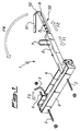
- Figure 1 shows the anti-theft device 1 for bicycles in one of the preferential embodiments of the present invention.
- the anti-theft device 1 is composed of a retainer base comprising a box 4 provided with a means of permanent anchorage 5. A rotating element 6 is fitted inside the box 4. An arm 2 provided with handle 7 and, in a more distant position, a hook 3 is connected to this element 6.
- the arm 2 and the hook 3 are integral with the element 6 and rotate with it.
- a curved element 8 is a sliding fit in a first chamber 45 (see figure 3) of the arm 2.
- the curved element 8 is composed of an initial straight portion 50 provided with holes 9 and a second portion 51 connected to the first by the elbow 52.
- the folding to elbow 52 is such that the second portion 51 is not perfectly parallel to the first 50, but is slightly angled towards it.
- the curved element 8 is in iron or steel bar stock.
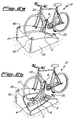
- Figure 2.a shows a view in perspective of a bicycle 21 locked to a block 20 by the anti-theft device according to the present invention.
- the block 20 contains a slot 27 that accepts at least one bicycle wheel 21 and within which is fitted the box 4 containing the element 6.
- the arm 2 is shown in a substantially vertical position and locking the frame 23 of the bicycle 21 by means of the curved element 8.
- the curved element 8 is locked in turn to the arm 2 by means of the barrel lock 22.
- substantially vertical position of the arm 2 is understood a position inclined at some degrees to the vertical.
- Figure 2.b shows in cutaway the anti-theft device according to the invention inside the block 20.
- the means of retention of the bicycle wheel are visible, consisting of the hook 3 integral with said element 6, and the box 4.
- said block 20 is a concrete block weighing between 150 kg and 300 kg.
- a plurality of said concrete blocks 20 may be linked in such a way as to keep the bicycle insertion slots 27 parallel, to form a rack of anti-theft devices.
- the blocks 20 are joined together by means of connecting elements (not shown) inserted in the holes 40.
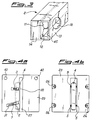
- Figure 3 shows in perspective the form of the rotating arm 2.
- the arm 2 has a substantially rectangular section and is divided by the partition 12 along its the own length.
- the partition 12 contains a hole 11, in line with a similar hole 10 in the side 13 so that the hole 10 and the hole 11 are coaxial.
- the partition 12 creates inside the arm 1, a first and a second chamber, and the second chamber, which is entirely hollow is permanently closed by a portion 14.
- Figure 4.a shows a top view of a concrete block 20 with the anti-theft device according to the present invention.
- a slot 27 which accepts at least one bicycle wheel, and two slots 30 and 31 that respectively allow the rotation of the hook 3 and of the arm 2.
- the slot 31 is angled slightly away from the perpendicular to the slot 27.
- Fig.4a also shows the holes 40 that allow the insertion of the connecting elements between blocks 20.
- Figure 4.b shows the underside of the block 20 which houses the box 4 anchored by means of the ties 5, set into the retaining base, to svitable tie centers 26.
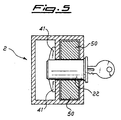
- Figure 5 shows in section, the arm 2 in which the barrel lock 22 has been inserted and locked.
- the lock 22 has been inserted through the hole 10 in the side 13, through one of the holes in the straight portion 50 of the curved element 8 and into the hole 11 in the partition 12.
- the lock 22 is fixed in position by means of the expanding anchorage lugs 41 which bear against the side of the partition 12 opposite the sliding curved element 8. This blocks the movement of the curved element 8 in the first channel 45 of the arm 2.
- the anchorage lugs 41 of the barrel lock 22 are protected against interference with breaking tools by the closed portion 14 which blocks the second chamber of the arm 2.
- the curved element 8 When the arm 2 is in a substantially vertical position, the curved element 8 can be inserted into the first chamber 45 of the arm 2.
- the curved element 8 can slide in the directions indicated by the arrows F1 and F2 and be positioned to lock the frame 23 of the bicycle 21.
- the lock 22 is inserted into the hole 10 on the side 13 of the arm 2.
- the lock passes through one of the plurality of holes in the straight portion 50 of said curved element 8 and finally through the hole 11 in the partition 12, coaxial with the hole 10 (see fig.5).
- the lock 22 is equipped with a means of expanding anchorage 41 which bears against the partition 12 on the side opposite the element 8.
- the means of anchorage 41 of the lock 22 is therefore inside said second chamber of the arm 2, which is hollow but closed permanently by the portion 14. This configuration of the arm 2 prevents the lock 22 from being forced or deliberately broken by safeguarding the anchorage lugs 41 from interference with breaking tools.
- the adjustment of the locking position of the arm 2 is achieved by selecting which of the holes 9 on the straight portion 50 of the element 8 to bring into alignment with the holes 10 and 11 on the arm 2 when locking with barrel lock 22.
- This adjustment in addition to the particular shape of the curved element 8 described above, allows various types and sizes of frames to be locked.
- the curved element 8 while constituting an integral part of the anti-theft device according to the present invention, is generally owned and carried around by the user together with the lock 22 and key, and could be conveniently clipped to the bicycle frame during normal use of the bicycle.
- the curved element 8 could be slid into the inside of the arm 2 but not be detachable from it, while the lock 22 and the related key are carried by the user.
- the handle 7 on the arm 2 comprises a U-shaped bar whose two pegs are inserted into holes along a line substantially perpendicular to the long side of the arm.
- a portion of the said curved element opposite to the straight portion with holes, could be inserted into the said U-shaped space.
- the second part of the elbow 51 of the element 8 is lengthened. This allows the frame of the bicycle 21 to be locked completely inside a fully closed circuit formed by the element 8, a portion of the arm 2 and by the pegs of the U-shaped handle. This solution prevents the bike being stolen by someone deflating the tyres of the bicycle 21 to create sufficient play between the elbow 52 and the frame 23 to remove the frame 23 from the curved element 8.
- a solution similar to that previously described provides for the arm 2 to have a third chamber parallel to and side by side with the second chamber; said third chamber being hollow and open ended in such a way as to receive the straight portion 51 of the curved element 8, to complete the locking circuit similarly to that described above .
Landscapes
- Engineering & Computer Science (AREA)
- Mechanical Engineering (AREA)
- Steering Devices For Bicycles And Motorcycles (AREA)
- Fittings On The Vehicle Exterior For Carrying Loads, And Devices For Holding Or Mounting Articles (AREA)
- Lock And Its Accessories (AREA)
Priority Applications (1)
| Application Number | Priority Date | Filing Date | Title |
|---|---|---|---|
| EP96830389A EP0818384A1 (fr) | 1996-07-11 | 1996-07-11 | Dispositif anti-vol pour bicyclettes |
Applications Claiming Priority (1)
| Application Number | Priority Date | Filing Date | Title |
|---|---|---|---|
| EP96830389A EP0818384A1 (fr) | 1996-07-11 | 1996-07-11 | Dispositif anti-vol pour bicyclettes |
Publications (1)
| Publication Number | Publication Date |
|---|---|
| EP0818384A1 true EP0818384A1 (fr) | 1998-01-14 |
Family
ID=8225961
Family Applications (1)
| Application Number | Title | Priority Date | Filing Date |
|---|---|---|---|
| EP96830389A Withdrawn EP0818384A1 (fr) | 1996-07-11 | 1996-07-11 | Dispositif anti-vol pour bicyclettes |
Country Status (1)
| Country | Link |
|---|---|
| EP (1) | EP0818384A1 (fr) |
Cited By (4)
| Publication number | Priority date | Publication date | Assignee | Title |
|---|---|---|---|---|
| FR2773765A1 (fr) * | 1998-01-16 | 1999-07-23 | Raffeneau Patrick | Dispositif antivol pour cycle |
| DE19925095A1 (de) * | 1998-12-11 | 2000-06-21 | Sven Riedl | Vorrichtung zur Halterung von Fahrzeugen, insbesondere von Fahrrädern |
| FR2825967A1 (fr) * | 2001-06-19 | 2002-12-20 | J C Decaux | Dispositif de parking pour bicyclette |
| ITVR20110175A1 (it) * | 2011-09-06 | 2013-03-07 | Alessandro Martini | Dispositivo per il parcheggio di biciclette. |
Citations (6)
| Publication number | Priority date | Publication date | Assignee | Title |
|---|---|---|---|---|
| US4126228A (en) * | 1972-11-30 | 1978-11-21 | Bala Lawrence G | Bicycle rack with lock |
| FR2402574A1 (fr) * | 1977-09-09 | 1979-04-06 | Palay Frederic | Dispositif antivol pour petits vehicules |
| GB2245238A (en) * | 1990-03-16 | 1992-01-02 | Ovalok U K Limited | Bicycle security device |
| EP0534928A1 (fr) * | 1991-09-23 | 1993-03-31 | PATENTE MARKEN LIZENZEN Verwaltungs- und Verwertungs-Gesellschaft m.b.H. | Dispositif pour bloquer des bicyclettes |
| CH683248A5 (de) * | 1992-03-30 | 1994-02-15 | Eric Misselwitz Hansjoerg Muel | Fahrradständer. |
| EP0587452A1 (fr) * | 1992-09-11 | 1994-03-16 | B. Dixon-Bate Limited | Perfectionnements aux dispositifs pour assurer une bicyclette contre le vol |
-
1996
- 1996-07-11 EP EP96830389A patent/EP0818384A1/fr not_active Withdrawn
Patent Citations (6)
| Publication number | Priority date | Publication date | Assignee | Title |
|---|---|---|---|---|
| US4126228A (en) * | 1972-11-30 | 1978-11-21 | Bala Lawrence G | Bicycle rack with lock |
| FR2402574A1 (fr) * | 1977-09-09 | 1979-04-06 | Palay Frederic | Dispositif antivol pour petits vehicules |
| GB2245238A (en) * | 1990-03-16 | 1992-01-02 | Ovalok U K Limited | Bicycle security device |
| EP0534928A1 (fr) * | 1991-09-23 | 1993-03-31 | PATENTE MARKEN LIZENZEN Verwaltungs- und Verwertungs-Gesellschaft m.b.H. | Dispositif pour bloquer des bicyclettes |
| CH683248A5 (de) * | 1992-03-30 | 1994-02-15 | Eric Misselwitz Hansjoerg Muel | Fahrradständer. |
| EP0587452A1 (fr) * | 1992-09-11 | 1994-03-16 | B. Dixon-Bate Limited | Perfectionnements aux dispositifs pour assurer une bicyclette contre le vol |
Cited By (4)
| Publication number | Priority date | Publication date | Assignee | Title |
|---|---|---|---|---|
| FR2773765A1 (fr) * | 1998-01-16 | 1999-07-23 | Raffeneau Patrick | Dispositif antivol pour cycle |
| DE19925095A1 (de) * | 1998-12-11 | 2000-06-21 | Sven Riedl | Vorrichtung zur Halterung von Fahrzeugen, insbesondere von Fahrrädern |
| FR2825967A1 (fr) * | 2001-06-19 | 2002-12-20 | J C Decaux | Dispositif de parking pour bicyclette |
| ITVR20110175A1 (it) * | 2011-09-06 | 2013-03-07 | Alessandro Martini | Dispositivo per il parcheggio di biciclette. |
Similar Documents
| Publication | Publication Date | Title |
|---|---|---|
| US3964611A (en) | Bicycle rack | |
| US3739609A (en) | Bicycle lock | |
| EP0429524B1 (fr) | Cadenas pour bicyclettes | |
| US5238125A (en) | Bicycle parking and storage rack | |
| US3970197A (en) | Rack and bicycle locking unit | |
| US4188808A (en) | Bicycle lock | |
| US3865244A (en) | Bicycle rack | |
| US5333923A (en) | Telescoping rid for protecting the side body structure of a vehicle | |
| US4019354A (en) | Motorcycle chain lock | |
| US6892913B1 (en) | Bicycle holder for vehicles | |
| GB2245238A (en) | Bicycle security device | |
| USRE38873E1 (en) | Quick release assembly for bicycle wheels | |
| US6637244B2 (en) | Water bottle holder with bicycle lock | |
| EP0818384A1 (fr) | Dispositif anti-vol pour bicyclettes | |
| US4725075A (en) | Antitheft device for motorcycles | |
| EP0091939A1 (fr) | Dispositif de verrouillage, en particulier pour des bicyclettes | |
| US5333476A (en) | U-lock with strength enhancing header extensions | |
| EP0634317A1 (fr) | Dispositif pour le stockage de bicyclettes | |
| EP0337552B1 (fr) | Porte-bagages avec fermeture à anse détachable | |
| US5102022A (en) | Locking device for spare tire carrier | |
| US4166560A (en) | Cargo carrier for motor vehicles | |
| GB2265346A (en) | Cycle security device | |
| US4747528A (en) | Anti-theft roof carrier structure for an automobile | |
| DK165630B (da) | Indretning til fastlaasning af en cykel | |
| GB2310839A (en) | Motorcycle wheel lock |
Legal Events
| Date | Code | Title | Description |
|---|---|---|---|
| PUAI | Public reference made under article 153(3) epc to a published international application that has entered the european phase |
Free format text: ORIGINAL CODE: 0009012 |
|
| AK | Designated contracting states |
Kind code of ref document: A1 Designated state(s): AT BE CH DE DK ES FI FR GB GR IE IT LI LU MC NL PT SE |
|
| AX | Request for extension of the european patent |
Free format text: AL;LT;LV;SI |
|
| AKX | Designation fees paid | ||
| RBV | Designated contracting states (corrected) | ||
| STAA | Information on the status of an ep patent application or granted ep patent |
Free format text: STATUS: THE APPLICATION IS DEEMED TO BE WITHDRAWN |
|
| 18D | Application deemed to be withdrawn |
Effective date: 19980715 |