EP0818575A2 - Procédé pour la préparation de débris de creusement - Google Patents
Procédé pour la préparation de débris de creusement Download PDFInfo
- Publication number
- EP0818575A2 EP0818575A2 EP97111548A EP97111548A EP0818575A2 EP 0818575 A2 EP0818575 A2 EP 0818575A2 EP 97111548 A EP97111548 A EP 97111548A EP 97111548 A EP97111548 A EP 97111548A EP 0818575 A2 EP0818575 A2 EP 0818575A2
- Authority
- EP
- European Patent Office
- Prior art keywords
- aggregate
- excavated material
- required amount
- excavated
- separator
- Prior art date
- Legal status (The legal status is an assumption and is not a legal conclusion. Google has not performed a legal analysis and makes no representation as to the accuracy of the status listed.)
- Withdrawn
Links
Images
Classifications
-
- E—FIXED CONSTRUCTIONS
- E02—HYDRAULIC ENGINEERING; FOUNDATIONS; SOIL SHIFTING
- E02D—FOUNDATIONS; EXCAVATIONS; EMBANKMENTS; UNDERGROUND OR UNDERWATER STRUCTURES
- E02D3/00—Improving or preserving soil or rock, e.g. preserving permafrost soil
-
- B—PERFORMING OPERATIONS; TRANSPORTING
- B28—WORKING CEMENT, CLAY, OR STONE
- B28C—PREPARING CLAY; PRODUCING MIXTURES CONTAINING CLAY OR CEMENTITIOUS MATERIAL, e.g. PLASTER
- B28C7/00—Controlling the operation of apparatus for producing mixtures of clay or cement with other substances; Supplying or proportioning the ingredients for mixing clay or cement with other substances; Discharging the mixture
- B28C7/04—Supplying or proportioning the ingredients
- B28C7/0404—Proportioning
- B28C7/0418—Proportioning control systems therefor
Definitions
- the present invention relates to a method for processing excavated material with admixture of aggregate as in claims 1 and 3 is described.
- the floor alone is generally of no use for reinstallation.
- the Floors are usually too wet and do not have the required load-bearing capacity.
- the remaining material is in most cases always for reinstallation not yet suitable, especially as far as cohesive soil material is concerned. It must then an additive is added in a further step, or stabilizing additives in order after mixing the separated Excavation material with the aggregate ultimately digestible material to obtain.
- the separation can take place with a so-called blade separator, which is offered under the trade name "ALU SM”.
- ALU SM This well-known Bucket separator is particularly suitable for use with wheel loaders and excavators.
- the back wall of the blade separator consists of quickly rotating ones Shafts that are equipped with disks. Interchangeable between the disks Schlegel attached.
- the carrier device for example the wheel loader or the excavator on which the bucket separator is arranged takes this Material like with a conventional shovel. With hydraulic drive then the waves are rotated. Through the energy input normal soils, but especially cohesive soils from the scree containing them separated and emerge through the spaces between the disks. Through the Clay floes and clayey material are broken down and in certain grain sizes separated. The debris remaining in the shovel - and thus the material that is not suitable for reinstallation - will then dumped separately.
- Binding agents are incorporated into soils on large-scale earthworks sites for example by means of mobile soil milling cutters with certain penetration depths or in stationary mixing plants.
- the mobile ARAN mixing system which uses a wheel loader the excavated material to be processed is loaded. Via an order volume this gets into the mixing trough. First there is the required amount of water admitted. Then, with a little time delay, more is added Aggregates directly from a dosing vehicle via a specially for this Purpose-developed injector. The plant works continuously. The intensely mixed material comes on after passing through the mixing trough Discharge conveyor and can be used from there directly on free-standing trucks be loaded. With this system too, it is necessary for profitability reasons that larger notes are processed.
- the present invention has for its object a method for To propose processing of excavated material with the addition of an aggregate, which is reliable, fast, flexible and above all with regard to is economical in smaller quantities.
- the blade separator which is known per se, is used in a previously unknown manner, in that a required amount of additive is added directly to the blade separator before the mixing or separation process begins.
- the metering device for the aggregate can consist of relatively small-sized devices, such as a silo and a conveyor in the form of a screw or a conveyor belt.
- soils that cannot be installed or excavation material that cannot be installed can also be processed where, for example, tilling machines cannot be used due to the limited space, such as in the case of pipe trenches, or where the use of mobile or stationary mixing plants is different due to the quantities involved not profitable.
- a large area of construction site equipment can be saved by the proposed method without the need for large-volume mixing plants.
- the intended recycling goals for the processing of excavated material can also be implemented economically for the first time.
- resources are conserved, since gravel and gravel from pits and quarries are hardly needed for reinstallation.
- the metering device can be arranged stationary on the one hand.
- the bucket separator has to be arranged so that the metering device together with the Excavators can be moved and it is particularly possible to control the amount of aggregate from the metering device arranged on the excavator corresponding feeds directly into the blade separator, in which the Excavation material has already been recorded.
- Such a metering device can in such a case, for example, from a dry matter container and a separate water tank, the separate delivery lines have and for example in one, above the blade separator
- the meterable suspension mixer arranged on the excavator arm ends the water and dry matter or binder mix to make it then, in the form of a suspension, dust-free into the blade separator to enter.
- the required aggregate also initially in the excavated material to be prepared is brought in before processing in the blade separator. Also before processing in the blade separator first finds a premix of the introduced aggregate with the excavated material instead. Only then is the pre-processed Excavated material was added to the bucket separator for subsequent use to be processed. Premixing the aggregate with the excavated material can with the bucket of an excavator or similar devices respectively. The main difference to the procedure described at the beginning is that the amount of aggregate required is not in this case is entered in the bucket separator, but beforehand in the excavated material. In both processes, the final processing of the excavated material takes place however, in the blade separator instead.
- the excavated material then is compressed and a compression control, in particular by means of a dynamic plate printing device, takes place to the determined results of the Compaction control directly or indirectly to the metering device for the Amount of aggregate to be sent to change there if necessary dosing the required amount of aggregate.
- a compression control in particular by means of a dynamic plate printing device, takes place to the determined results of the Compaction control directly or indirectly to the metering device for the Amount of aggregate to be sent to change there if necessary dosing the required amount of aggregate.
- the measurement results can be transmitted via radio or via direct data transmission to control the dosing device for the Aggregates.
- the material that can be built in is obtained is temporarily stored in order to then transported to the place of introduction to become.
- the metering device from a silo which the Contains aggregate, a controllable output device for the aggregate and a conveyor belt or a screw for transporting the output Aggregate exists.
- the above facilities are in As a rule, it is available on the construction site and it is not necessary to purchase it from other institutions to achieve the desired success.
- the metering device can preferably be designed so that it can be used with the Excavator, which has the bucket separator, can be implemented so that the dosing device is moved together with the excavator in the working direction can be.
- the output device can advantageously be controlled via a time switch, thereby increasing the predetermined amount of aggregate for each operation receive.
- the output device can advantageously be controlled via a remote control.
- the aggregate consists of binders, in particular Lime, cement, lime powder, the aforementioned materials also mixed as an additive can be added.
- the blade separator which is known per se, is thus used for complete reprocessing of excavated material with simultaneous separation of unwanted grain sizes and with the addition of additives to obtain ready-to-install Material used.
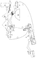
- a particularly preferred method sequence is described below using a sequence diagram described on a trench construction site.
- a pipe trench 2 is shown, in which a pipe is to be laid.
- Excavation takes place with an excavator 4 in area 6 of the pipe trench 2.
- the Soil is loosened on the trench construction site by the excavator 4 and with trucks 8 is the excavated material to a nearby central processing station Brought 10.
- the excavated material from a second Charger here a second excavator 12 added.
- a bucket separator for mounting 14 Arranged on the excavator 12 is a bucket separator for mounting 14. Before starting up the bucket separator 14 this becomes after picking up the untreated excavated material a metering device for aggregates, here consisting of a silo 16 with Move worm 18 below. There will be one beforehand certain amount of additives in the blade separator 14 to the therein excavated material is added.
- the blade separator 14 is moved further to one Nearby interim storage facility 20.
- the blade separator 14 is in operation there taken and in addition to a separation of unwanted grain sizes, So a separation of rubble, at the same time a mixing process between the Excavation material and the added aggregate. While the unwanted Grain sizes remain in the blade separator, the now treated and ready-to-install, remaining material accumulated on the intermediate storage 20, by having the blade separator 14 after the treatment after one pass the shafts to unlock the excavated material at the same time Mixing with the aggregate leaves.
- the blade separator 14 is then moved back to the processing station 10, to pick up untreated excavation material for further treatment. It goes without saying that for the treatment of the excavated material very much little space is required and, ideally, the excavator 12 does not even move must be, but only about pivoting movements and retracting and extending of the excavator arm can reach the corresponding jobs.
- the material which is now treated and can be installed is preferably from Interim storage facility 20 is loaded onto a further truck 24 in order to bring it back into the bring in excavated pipe trench 2 in the area 26. After dumping the built-in material in the area 26 is compressed with simultaneous Compaction control, especially with a dynamic plate printing device. The quality or properties of the installed and compacted material can be checked immediately for load-bearing capacity and other values.
- the result is forwarded to the dosing device for the aggregate basically consists of the silo 16 and the screw 18.
- the edition of the Aggregate from the silo 16 to the screw 18 is carried out via a controllable Output device 28, which can preferably be controlled via a timer is and in particular can also be controlled via a remote control.
- the Results obtained can correct the amount of required Additive conditions that are implemented directly in the output device 28 can be done by adding either more or less aggregate to the Snail 18 is issued.
- the transmission of the compression values (density measurement) after checking in Area 26 of the pipe trench 2 can, for example, be transmitted to the staff via radio communication of the excavator 12. From there, the output device can then use a signal 28 can be controlled. But it is just as possible, the values the compression control directly to the output device 28 from the area 26 to transmit from.
- the required aggregate is introduced directly into the blade separator 14 will.
- the aggregate is removed from the silo 16 by means of a screw conveyor 18 promoted in the blade separator 14.
- the worm 18 can also over a radio remote control can be put into operation directly from the excavator 14.
- the required amount of aggregate can be checked in advance in a laboratory can be determined, then via a time control using the output device 28 to be metered exactly, with the application on the screw 18 via the output device 28, which also during operation can be controlled that changed amounts of aggregate on the Snail 18 can be abandoned.
Landscapes
- Engineering & Computer Science (AREA)
- Structural Engineering (AREA)
- Life Sciences & Earth Sciences (AREA)
- Paleontology (AREA)
- Soil Sciences (AREA)
- Environmental & Geological Engineering (AREA)
- General Life Sciences & Earth Sciences (AREA)
- Mining & Mineral Resources (AREA)
- Agronomy & Crop Science (AREA)
- Civil Engineering (AREA)
- General Engineering & Computer Science (AREA)
- Automation & Control Theory (AREA)
- Chemical & Material Sciences (AREA)
- Dispersion Chemistry (AREA)
- Preparation Of Clay, And Manufacture Of Mixtures Containing Clay Or Cement (AREA)
- Tea And Coffee (AREA)
Applications Claiming Priority (2)
| Application Number | Priority Date | Filing Date | Title |
|---|---|---|---|
| DE19627465 | 1996-07-08 | ||
| DE1996127465 DE19627465C2 (de) | 1996-07-08 | 1996-07-08 | Verfahren zum Aufbereiten von Aushubmaterial |
Publications (2)
| Publication Number | Publication Date |
|---|---|
| EP0818575A2 true EP0818575A2 (fr) | 1998-01-14 |
| EP0818575A3 EP0818575A3 (fr) | 1998-07-08 |
Family
ID=7799242
Family Applications (1)
| Application Number | Title | Priority Date | Filing Date |
|---|---|---|---|
| EP97111548A Withdrawn EP0818575A3 (fr) | 1996-07-08 | 1997-07-08 | Procédé pour la préparation de débris de creusement |
Country Status (2)
| Country | Link |
|---|---|
| EP (1) | EP0818575A3 (fr) |
| DE (1) | DE19627465C2 (fr) |
Cited By (1)
| Publication number | Priority date | Publication date | Assignee | Title |
|---|---|---|---|---|
| DE10131869B4 (de) * | 2001-06-25 | 2008-10-30 | Ernst Josef Kronenberger | Verfahren zur Neutralisierung von Calciumhydroxid Ca(OH)2 in mit Kalk verbesserten Böden zur Verhinderung der puzzolanischen Reaktion |
Families Citing this family (10)
| Publication number | Priority date | Publication date | Assignee | Title |
|---|---|---|---|---|
| DE19803240A1 (de) | 1998-01-28 | 1999-07-29 | Voith Sulzer Papiertech Patent | Farbvorhang-Auftragsvorrichtung |
| DE19822325A1 (de) * | 1998-05-19 | 1999-12-09 | Rainer Schrode Gmbh | Verfahren zum Aufbereiten von Bodenaushub |
| DE19950435C1 (de) * | 1999-10-19 | 2001-03-29 | Dietmar Mothes Gmbh Strasen Un | Vorrichtung zum Aufbereiten von Aushubmaterial |
| AT409008B (de) * | 2000-07-11 | 2002-05-27 | Brunner Karl Heinz | Mineralisches haufwerk, verfahren zu seiner herstellung, künettenverfüllmaterial sowie künettenfüllungen |
| DE10050850B4 (de) * | 2000-10-13 | 2004-10-07 | Paal Baugeräte GmbH | Vorrichtung zur Mischung von Aushubmaterial mit Zuschlagstoffen |
| DE10056406C2 (de) * | 2000-11-14 | 2002-11-28 | Baufeld Umwelt Engineering Gmb | Vorrichtung zur Vorkonditionierung carbo- und petrostämmiger Altlastmaterialien |
| DE10111300B4 (de) | 2001-03-09 | 2007-12-13 | Schenk, Jürgen | Aufbereitungsvorrichtung insbesondere für Aushub |
| DE10226232A1 (de) * | 2002-06-13 | 2004-01-15 | Ernst Josef Kronenberger | Verfahren zur Aufbereitung von Aushubmassen und Herstellen eines Bodenbaustoffes |
| DE102010021335A1 (de) | 2010-05-22 | 2011-11-24 | Frank Baldinger | Verfahren und Vorrichtung zur Herstellung einer Rohrbettung |
| PE20181213A1 (es) | 2015-11-16 | 2018-07-24 | Maurice Garzon | Metodo para formar un terreno de cimentacion estable |
Family Cites Families (5)
| Publication number | Priority date | Publication date | Assignee | Title |
|---|---|---|---|---|
| DE3127350C2 (de) * | 1981-07-10 | 1985-01-03 | Hans 8202 Bad Aibling Ribbert | Verfahren zur Bodenverfestigung |
| FR2536771A1 (fr) * | 1982-11-30 | 1984-06-01 | Franex | Installation pour l'alimentation volumetrique ou ponderale de materiaux, le dosage de produits pulverulents, de liants hydrauliques ou hydrocarbones, et leur malaxage pour realiser un melange destine a etre utilise pour l'amelioration et/ou la stabilisation des sols en travaux de terrassements, routes, aerodromes et barrages masses |
| US5379534A (en) * | 1991-01-22 | 1995-01-10 | Negishi; Jinichiro | Bucket equipped with mixing device, excavation machine having the bucket, and soil improvement method using the excavation machine |
| DE4303285A1 (de) * | 1993-02-05 | 1994-08-11 | Weiss Gmbh & Co Leonhard | Verfahren zur tiefgründigen Bodenverfestigung und Einrichtung zur Durchführung |
| DE4409507A1 (de) * | 1994-03-19 | 1995-09-21 | Walter Schoelkopf | Vorrichtung zur Aufbereitung von Erdreich zu einem standfesten Baumaterial |
-
1996
- 1996-07-08 DE DE1996127465 patent/DE19627465C2/de not_active Expired - Fee Related
-
1997
- 1997-07-08 EP EP97111548A patent/EP0818575A3/fr not_active Withdrawn
Cited By (1)
| Publication number | Priority date | Publication date | Assignee | Title |
|---|---|---|---|---|
| DE10131869B4 (de) * | 2001-06-25 | 2008-10-30 | Ernst Josef Kronenberger | Verfahren zur Neutralisierung von Calciumhydroxid Ca(OH)2 in mit Kalk verbesserten Böden zur Verhinderung der puzzolanischen Reaktion |
Also Published As
| Publication number | Publication date |
|---|---|
| DE19627465A1 (de) | 1996-12-19 |
| DE19627465C2 (de) | 1997-08-07 |
| EP0818575A3 (fr) | 1998-07-08 |
Similar Documents
| Publication | Publication Date | Title |
|---|---|---|
| DE60106267T2 (de) | Recyclat und anlage zum mischen | |
| DE19627465C2 (de) | Verfahren zum Aufbereiten von Aushubmaterial | |
| DE19727549C2 (de) | Vorrichtung sowie Verfahren zum Ausheben und Auffüllen von Erdreich | |
| DE19530827C2 (de) | Verfahren und Vorrichtung zur Herstellung von Schlitzwänden | |
| WO2005025752A2 (fr) | Dispositif de traitement de deblai | |
| DE69923310T2 (de) | Verfahren zur bodenstabilisierung für strassenbauarbeiten | |
| WO2004101156A1 (fr) | Procede et dispositif de traitement de deblais | |
| DE4101015C2 (de) | Verfahren zur Herstellung einer Dichtungsschlitzwand | |
| DE102017122400A1 (de) | Verfahren und Vorrichtung zur Bereitstellung von Bodenmörtel | |
| DE3418180A1 (de) | Vortriebsschild | |
| DE19950435C1 (de) | Vorrichtung zum Aufbereiten von Aushubmaterial | |
| DE2655542C3 (de) | Verfahren zum hydraulischen Einbringen von Versatz sowie Einrichtung zur Durchführung des Verfahrens | |
| DE102021107719B3 (de) | Verfahren zur Gewinnung eines sandartigen Bodenbaustoffs und dessen Verwendung zur Herstellung von Beton | |
| DE102007024057B4 (de) | Verfahren zur Verfestigung und/oder Abdichtung lockerer geologischer Formationen im Zuge von geotechnischen Baumaßnahmen | |
| DE19602604A1 (de) | Bodenmörtel | |
| DE69406988T2 (de) | Vorrichtung und Verfahren zur Herstellung von monolithischen Schlitzwänden oder dergleichen | |
| EP2050517B1 (fr) | Procédé de traitement de matériau de sédiment d'eau ou de sol minéral contaminé | |
| DE60000529T2 (de) | Verfahren und Vorrichtung zur Behandlung von Materialien hauptsächlich bestehend aus feuchtem Ton, insbesondere Bodenaushub | |
| DE102008050175B4 (de) | Verfahren zur Herstellung eines temporär fließfähigen Verfüllbaustoffs, insbesondere für den Einbau in Ausschachtungen | |
| DE10337590A1 (de) | Verfahren und Vorrichtung zum Aufbereiten von Aushub | |
| DE69918471T2 (de) | Verfahren und vorrichtung zur behandlung von bodenaushub und erhaltene aufschüttung | |
| EP0959184B1 (fr) | Procédé pour traiter des débris de creusement | |
| AT521538B1 (de) | Künettenfüllmaterial sowie Verfahren zu dessen Wiederaufbereitung | |
| DE20021092U1 (de) | Vorrichtung zur Einbringung von Materialien in den Erdboden | |
| DE10038010A1 (de) | Vorrichtung zur Aufbereitung von Erdstoffen |
Legal Events
| Date | Code | Title | Description |
|---|---|---|---|
| PUAI | Public reference made under article 153(3) epc to a published international application that has entered the european phase |
Free format text: ORIGINAL CODE: 0009012 |
|
| AK | Designated contracting states |
Kind code of ref document: A2 Designated state(s): AT CH DE FI FR LI |
|
| PUAL | Search report despatched |
Free format text: ORIGINAL CODE: 0009013 |
|
| AK | Designated contracting states |
Kind code of ref document: A3 Designated state(s): AT BE CH DE DK ES FI FR GB GR IE IT LI LU MC NL PT SE |
|
| 17P | Request for examination filed |
Effective date: 19980731 |
|
| AKX | Designation fees paid |
Free format text: AT CH DE FI FR LI |
|
| RBV | Designated contracting states (corrected) |
Designated state(s): AT CH DE FI FR LI |
|
| 17Q | First examination report despatched |
Effective date: 19990409 |
|
| STAA | Information on the status of an ep patent application or granted ep patent |
Free format text: STATUS: THE APPLICATION HAS BEEN WITHDRAWN |
|
| 18W | Application withdrawn |
Withdrawal date: 19990624 |