EP0818585B1 - Unterputz-Anschlussstück - Google Patents
Unterputz-Anschlussstück Download PDFInfo
- Publication number
- EP0818585B1 EP0818585B1 EP97110966A EP97110966A EP0818585B1 EP 0818585 B1 EP0818585 B1 EP 0818585B1 EP 97110966 A EP97110966 A EP 97110966A EP 97110966 A EP97110966 A EP 97110966A EP 0818585 B1 EP0818585 B1 EP 0818585B1
- Authority
- EP
- European Patent Office
- Prior art keywords
- valve
- bore
- water
- connector according
- concealed connector
- Prior art date
- Legal status (The legal status is an assumption and is not a legal conclusion. Google has not performed a legal analysis and makes no representation as to the accuracy of the status listed.)
- Expired - Lifetime
Links
- XLYOFNOQVPJJNP-UHFFFAOYSA-N water Substances O XLYOFNOQVPJJNP-UHFFFAOYSA-N 0.000 claims abstract description 70
- 230000001174 ascending effect Effects 0.000 claims description 2
- 238000013022 venting Methods 0.000 claims 2
- 238000009423 ventilation Methods 0.000 abstract description 23
- 238000005276 aerator Methods 0.000 description 6
- 238000009434 installation Methods 0.000 description 5
- 238000010276 construction Methods 0.000 description 1
- 238000011010 flushing procedure Methods 0.000 description 1
- 238000012423 maintenance Methods 0.000 description 1
- 239000000463 material Substances 0.000 description 1
- 230000036316 preload Effects 0.000 description 1
- 238000007789 sealing Methods 0.000 description 1
- 238000011144 upstream manufacturing Methods 0.000 description 1
Images



Classifications
-
- E—FIXED CONSTRUCTIONS
- E03—WATER SUPPLY; SEWERAGE
- E03C—DOMESTIC PLUMBING INSTALLATIONS FOR FRESH WATER OR WASTE WATER; SINKS
- E03C1/00—Domestic plumbing installations for fresh water or waste water; Sinks
- E03C1/02—Plumbing installations for fresh water
- E03C1/021—Devices for positioning or connecting of water supply lines
-
- E—FIXED CONSTRUCTIONS
- E03—WATER SUPPLY; SEWERAGE
- E03C—DOMESTIC PLUMBING INSTALLATIONS FOR FRESH WATER OR WASTE WATER; SINKS
- E03C1/00—Domestic plumbing installations for fresh water or waste water; Sinks
- E03C1/02—Plumbing installations for fresh water
- E03C1/04—Water-basin installations specially adapted to wash-basins or baths
- E03C1/042—Arrangements on taps for wash-basins or baths for connecting to the wall
-
- Y—GENERAL TAGGING OF NEW TECHNOLOGICAL DEVELOPMENTS; GENERAL TAGGING OF CROSS-SECTIONAL TECHNOLOGIES SPANNING OVER SEVERAL SECTIONS OF THE IPC; TECHNICAL SUBJECTS COVERED BY FORMER USPC CROSS-REFERENCE ART COLLECTIONS [XRACs] AND DIGESTS
- Y10—TECHNICAL SUBJECTS COVERED BY FORMER USPC
- Y10T—TECHNICAL SUBJECTS COVERED BY FORMER US CLASSIFICATION
- Y10T137/00—Fluid handling
- Y10T137/3149—Back flow prevention by vacuum breaking [e.g., anti-siphon devices]
- Y10T137/3185—Air vent in liquid flow line
- Y10T137/3294—Valved
- Y10T137/3331—With co-acting valve in liquid flow path
-
- Y—GENERAL TAGGING OF NEW TECHNOLOGICAL DEVELOPMENTS; GENERAL TAGGING OF CROSS-SECTIONAL TECHNOLOGIES SPANNING OVER SEVERAL SECTIONS OF THE IPC; TECHNICAL SUBJECTS COVERED BY FORMER USPC CROSS-REFERENCE ART COLLECTIONS [XRACs] AND DIGESTS
- Y10—TECHNICAL SUBJECTS COVERED BY FORMER USPC
- Y10T—TECHNICAL SUBJECTS COVERED BY FORMER US CLASSIFICATION
- Y10T137/00—Fluid handling
- Y10T137/6851—With casing, support, protector or static constructional installations
- Y10T137/6966—Static constructional installations
- Y10T137/6969—Buildings
- Y10T137/698—Wall
-
- Y—GENERAL TAGGING OF NEW TECHNOLOGICAL DEVELOPMENTS; GENERAL TAGGING OF CROSS-SECTIONAL TECHNOLOGIES SPANNING OVER SEVERAL SECTIONS OF THE IPC; TECHNICAL SUBJECTS COVERED BY FORMER USPC CROSS-REFERENCE ART COLLECTIONS [XRACs] AND DIGESTS
- Y10—TECHNICAL SUBJECTS COVERED BY FORMER USPC
- Y10T—TECHNICAL SUBJECTS COVERED BY FORMER US CLASSIFICATION
- Y10T137/00—Fluid handling
- Y10T137/8593—Systems
- Y10T137/87249—Multiple inlet with multiple outlet
Definitions
- the invention relates to a flush-mounted connector for at least one water valve, in particular water mixing valve and / or water distribution valve, with at least an inflow opening and at least one outflow opening, with a connection surface for a Water valve is formed.
- a mixing valve cartridge can be fastened in a sealed manner with clamping screws, the connecting surface being arranged parallel to the surface of the building wall.
- a connection for the incoming cold and hot water and a connection vertically one above the other for the discharge of mixed water is provided on each side in an approximately horizontal plane.
- the concealed connection piece 'a water distribution valve is arranged in a separate bore, with which the mixed water generated in the mixing valve cartridge can be supplied either to the upper or the lower connection, the water distribution valve being designed such that it automatically returns to a preferred outlet position after the outflowing mixed water has been shut off.
- EP-A-0 495 372 discloses a water tap fitting which can be fastened to a wash basin and / or sink, in which a ventilation device arranged in a cylindrical housing is provided in the fitting housing to prevent the sucking back of used water.
- the ventilation device is connected to the atmosphere via a ventilation channel, which opens into a shower hose guide and a tubular fastening hose.
- a connecting device is known from EP-A-0 392 176, in which a tap fitting with a flange formed on the tap fitting housing can be connected to a connecting piece.
- the invention has for its object at the outset specified flush-mounted connector the installation to simplify the tube aerator, and the tube aerator to train more cost-effectively.
- the advantages that can be achieved with the invention are, in particular, that a special installation of tube aerators is no longer required.
- a special pipe aerator housing is no longer required for the individual pipe aerators, since the ventilation device is integrated in the flush-mounted connector.
- a transverse bore led out laterally from the flush-mounted connecting piece is arranged so as to rise from the bore for receiving the ventilation device, so that if leaks occur in the ventilation device during operation of the fitting, these can be taken up by a drip water drainage channel.
- the ventilation device can advantageously be designed as a structural unit which can be used as a unit in the bore of the flush-mounted connecting piece.
- the multi-way valve can advantageously be arranged one behind the other with a further second valve.
- the closure members of both valves of the ventilation device are expediently designed as balls.
- a snap ring can be provided in the plug-in position in the bore for securely holding the ventilation device or a plate can be fastened in a sealed manner to the connection surface of the flush-mounted connection piece with screws and round cord rings.
- threaded holes can be provided on the plate, into which clamping screws can be screwed for fastening a mixing valve cartridge, so that a secure and tight attachment of the mixing valve cartridge is ensured.
- the ventilation device is easily accessible for maintenance purposes.
- the arrangement of the ventilation device upstream of a water distribution valve also ensures that both mixed water connections are protected by one ventilation device.
- the drip water drainage channel can advantageously be formed in the flush-mounted connector so that it opens into a drip water pipe. The leakage water can then be drained out of the building wall to the back of the cover rosette via the drip water line.
- the leakage water can be provided by a Drain the opening at the bottom edge of the rosette.
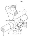
- the flush-mounted connector 1 shown in FIGS. 1 to 3 has two diametrically opposed horizontal connections 14, 15 for the incoming cold and hot water.
- the connections 14, 15 are each connected to a connection channel for cold and hot water 133, 134 in a plate 13.
- a mixing valve cartridge 3 with clamping screws 31, which can be screwed into threaded bores 311, can be fastened to the front of the plate 13, as can be seen in particular from FIGS. 1 and 2 of the drawing.
- the mixed water generated in the mixing valve cartridge 3 is fed back to the flush-mounted connection piece 1 via a mixed water connection channel 135 in the plate 13, and fed to different consumers via the mixed water connections arranged vertically one above the other.
- the plate 13 is fastened with screws 130 and sealing rings 131 to a connection surface 10 of the flush-mounted connection piece 1 which is formed parallel to the building wall 100, the mixed water connection channel 135 opening into a bore 11 starting from the connection surface 10, in which a ventilation device 2 designed as a structural unit is arranged is, as can be seen in particular from FIG. 2.
- the bore 11 is formed horizontally in the flush-mounted connector 1 and opens into a downstream transverse bore 110, which - starting from the interface - leads out of the flush-mounted connector 1 ascending on both sides and thus the downstream region of the bore 11 connects with the atmosphere.
- a drip water drainage channel 12 is formed in the flush-mounted connection piece 1, which opens into a drip water pipe 121 which is also arranged at a slope.
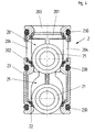
- the ventilation device 2 is arranged in a cylindrical housing 23, as can be seen from FIG. 2 and in particular from FIG. 4.
- O-rings 230 are arranged in annular grooves on the outer casing, with which the housing 23 is sealed in the plug-in position in the bore 11.
- the mixed water generated by the mixing valve cartridge 3 passes through the inflow opening 203 and the annular valve seat 201 into the housing 23 of a multi-way valve 20.
- a spherical valve closure member 21 is axially movable between the two valve seats 201 and 202.
- Outflow openings 204 are formed radially in the wall of the housing 23 between the valve seats 201 and 202.
- a further valve 25 is arranged downstream of the multi-way valve 20, the spherical closure member 21 of which cooperates with a valve seat 22 which is also annular.
- the housing 23 is secured axially on the one hand by an annular shoulder in the bore 11 and on the other hand by the plate 13.
- an annular space 1111 is formed in the bore 11, which is connected via an outflow channel 111 to a receiving bore 118 for a water distribution valve 4.
- the receiving bore 118 is on the other hand connected to the upper mixed water connection 16 and via a connecting channel 112 to the lower mixed water connection 16 of the flush-mounted connector 1.
- the flush-mounted connector is useful in the Fig. 1 shown training assembled at the factory. Then at the construction site after installation of the connections 14, 15 for the incoming cold and Hot water and the two mixed water connections 16 and pressing and flushing the connecting lines the flush-mounted connector 1 with a plastering template 17, as shown in particular in FIG. 2 is plastered in the building wall 100. After that can the plastering template 17 from the flush-mounted connector 1 removed, the mixing valve cartridge 3 with a cover 300 and the water distribution valve 4 are screwed into the receiving bore 118. The opening in the building wall 100 can then with a cover rosette 5 are covered after the Drip water line 121 shortened to the required level has been. To drain the drip water is on an opening 51 is provided on the lower edge of the cover rosette. After applying the cover rosette 5 can finally then on the valve cartridge 3 an operating lever 30 are attached so that afterwards the device is ready for operation.
- the cold and supplied via the connections 14, 15 Hot water enters through the connection channels 133, 134 in the mixing valve cartridge, in the with the help of the operating lever 30 set mixing and quantity setting Mixed water is generated and via the mixed water connection channel 135 in the bore 11 of the flush-mounted connector 1 is delivered.
- the mixed water flows axially through the inflow opening 203 into the housing 23 and presses the spherical valve closure member 21 against the valve seat 202 and flows through the outflow openings 204 in the annular space 1111 and from here through the drain channel 111 in the mounting hole 118.
- it will either upper mixed water connection 16, z. B. to a hose shower, or via the connecting channel 112 to the lower one Mixed water outlet 16, e.g.
- the ventilation device 2 leak or due to vacuum surges Leak drip water from the ventilation device 2, in both cases the dripping water gets into the lower one Area of the transverse bore 110 and becomes harmless from here through the drip water drainage channel 12 and Drip water pipe 121 led out of the building wall 100 and arrives at the outlet below the rosette 5.
- the ventilation device 2 is horizontal in the hole 11 arranged in the flush-mounted connector 1.
- the ventilation device 2 also in a different position in the flush-mounted connector 1 to be ordered.
- the ventilation device 2 for a more vertical installation in the flush-mounted connector 1 provided and with spherical valve closure members 21 provided from a material are made, which is lighter than water, so that they swim in the water.
- the valve closure member 21 additionally with a spring 251 against the valve seat 22 pressed with a certain bias becomes.
- the preload can be designed in this way be that the valve closure member 21 at atmospheric Internal pressure in valve 25 kept in the closed position is.
- valve closure member experiences in particular 21 in the multi-way valve 20 from the flowing water has a buoyancy and is thereby pressed against the valve seat 202. Kick against it a negative pressure in the inflow opening 203, so the valve closure member 21 is sucked back against the buoyancy and thereby comes into contact with the valve seat 201, so that further sucking back is prevented being, at the same time a connection from the outflow openings 204 to the atmosphere via valve 25 will be produced.
Landscapes
- Life Sciences & Earth Sciences (AREA)
- Engineering & Computer Science (AREA)
- Hydrology & Water Resources (AREA)
- Public Health (AREA)
- Water Supply & Treatment (AREA)
- Health & Medical Sciences (AREA)
- Quick-Acting Or Multi-Walled Pipe Joints (AREA)
- Catching Or Destruction (AREA)
- Self-Closing Valves And Venting Or Aerating Valves (AREA)
- Domestic Plumbing Installations (AREA)
- Valve Housings (AREA)
- Table Devices Or Equipment (AREA)
- Taps Or Cocks (AREA)
- Check Valves (AREA)
Description
Außerdem ist aus der EP-A-0 495 372 eine an einen Wasch- und/oder Spültisch befestigbare Wasserzapfarmatur bekannt, bei der im Armaturengehäuse zur Verhinderung eines Rücksaugens von Brauchwasser eine in einem zylindrischen Gehäuse angeordnete Belüftungseinrichtung vorgesehen ist. Die Belüftungseinrichtung ist dabei über einen Belüftungskanal, der in einer Brauseschlauchführung und einem rohrförmigen Befestigungsschlauch mündet, mit der Atmosphäre verbunden.
Ferner ist aus der EP-A-0 392 176 eine Anschlussvorrichtung bekannt, bei der an einem Anschlussstück eine Zapfarmatur mit einem am Zapfarmaturengehäuse ausgebildeten Flansch anschließbar ist.
Vorteilhaft kann die Belüftungsvorrichtung als Baueinheit ausgebildet werden, die als Einheit in die Bohrung des Unterputz-Anschlußstücks einsetzbar ist. Hierbei kann zweckmäßig das Mehrwegeventil mit einem weiteren zweiten Ventil hintereinander angeordnet werden. Die Verschlußglieder beider Ventile der Belüftungseinrichtung werden zweckmäßig als Kugeln ausgebildet.
Schließlich kann vorteilhaft in dem Unterputz-Anschlußstück der Tropfwasserabflußkanal so ausgebildet werden, dass er in einer Tropfwasserleitung mündet. Das Leckwasser kann dann über die Tropfwasserleitung aus der Gebäudewand heraus zur Rückseite der Abdeckrosette abgeleitet werden.
- Fig. 1
- ein Unterputz-Anschlußstück in Perspektiv-Darstellung;
- Fig. 2
- das in Fig. 1 dargestellte Unterputz-Anschlußstück im Längsschnitt mit einer Einputzschablone, einer Mischventilkartusche und Anschlußleitungen in einer Gebäudewand installiert;
- Fig. 3
- das in Fig. 1 dargestellte Unterputz-Anschlußstück in Seitenansicht mit einem Mischventil, einem Wasserverteilventil und einer Abdeckrosette fertig montiert in einer Gebäudewand;
- Fig. 4
- die in Fig. 2 gezeigte, als Baueinheit ausgebildete Belüftungseinrichtung in vergrößerter Darstellung im Längsschnitt;
- Fig. 5
- ein anderes Ausführungsbeispiel der Belüftungseinrichtung in vergrößerter Darstellung im Längsschnitt.
Die Platte 13 ist mit Schrauben 130 und Dichtringen 131 an einer parallel zur Gebäudewand 100 ausgebildeten Anschlußfläche 10 des Unterputz-Anschlußstücks 1 befestigt, wobei der Mischwasseranschlußkanal 135 in eine von der Anschlußfläche 10 ausgehende Bohrung 11 mündet, in der eine als Baueinheit ausgebildete Belüftungseinrichtung 2 angeordnet ist, wie es insbesondere aus Fig. 2 zu entnehmen ist. Die Bohrung 11 ist hierbei waagerecht in dem Unterputz-Anschlußstück 1 ausgebildet und mündet in einer stromabwärts angeordneten Querbohrung 110, die - von der Schnittstelle ausgehend - ansteigend zu beiden Seiten aus dem Unterputz-Anschlußstück 1 herausgeführt ist und somit den stromabwärts gelegenen Bereich der Bohrung 11 mit der Atmosphäre verbindet. An der am tiefsten gelegenen Stelle der Querbohrung 110 ist ein Tropfwasserabflußkanal 12 in dem Unterputzanschlußstück 1 ausgebildet, der in eine ebenfalls mit Gefälle angeordnete Tropfwasserleitung 121 mündet.
Im Bereich der radial ausgebildeten Abströmöffnungen 204 ist in der Bohrung 11 ein Ringraum 1111 ausgebildet, der über einen Abflußkanal 111 mit einer Aufnahmebohrung 118 für ein Wasserverteilventil 4 verbunden ist. Die Aufnahmebohrung 118 ist andererseits mit dem oberen Mischwasseranschluß 16 und über einen Verbindungskanal 112 mit dem unteren Mischwasseranschluß 16 des Unterputz-Anschlußstücks 1 verbunden.
Claims (8)
- Unterputz-Anschlußstück für wenigstens ein Wasserventil, insbesondere Wassermischventil und/oder Wasserverteilventil, mit wenigstens einer Zuflußöffnung und wenigstens einer Abflußöffnung, wobei in Gebrauchsstellung stirnseitig eine Anschlußfläche für ein Wasserventil ausgebildet ist,
dadurch gekennzeichnet, daßvon der Anschlußfläche (10) ausgehend eine Bohrung (11) für den Abfluß ausgebildet ist, in der eine Belüftungseinrichtung (2) in Form eines Mehrwegeventils (20) angeordnet ist, welches axial vom ausfließenden Wasser anströmbar ist,das Mehrwegeventil (20) mit zwei ringförmigen Ventilsitzen (201,202) versehen ist, zwischen denen ein Ventilverschlußglied (21) beweglich angeordnet ist, und der Abfluß radial zwischen den beiden Ventilsitzen (201,202) in der Wandung vorgesehen ist,die Bohrung (11) als in Gebrauchsstellung waagerechte Sackbohrung ausgebildet ist, deren Endbereich hinter dem stromabwärts gelegenen Ventilsitz (202 oder 22) eine Querbohrung (110) schneidet, die mit der Atmosphäre verbunden ist,die Querbohrung (110) vom Schnittbereich mit der Sackbohrung (11) in Gebrauschsstellung steigend angeordnet ist. - Unterputz-Anschlußstück nach Anspruch 1, dadurch gekennzeichnet, daß am stromabwärts gelegenen Endbereich der Bohrung (11) ein Tropfwasserabflußkanal (12) ausgebildet ist.
- Unterputz-Anschlußstück nach Anspruch 2, dadurch gekennzeichnet, daß am Endbereich des Tropfwasserabflußkanals (12) eine Tropfwasserleitung (121) angeordnet ist, die mit Gefälle aus einer Gebäudewand (100) herausführbar ist und im Bereich einer Abdeckrosette (5) mündet.
- Unterputz-Anschlußstück nach einem der Ansprüche 1 bis 3, dadurch gekennzeichnet, daß die Belüftungseinrichtung (2) als Baueinheit in der Bohrung (11) angeordnet ist, wobei zur Sicherung in der Stecklage eine an der Anschlußfläche (10) befestigbare Platte (13) vorgesehen ist, an der auch das Wasserventil, insbesondere eine Mischventilkartusche (3), befestigbar ist.
- Unterputz-Anschlußstück nach Anspruch 4, dadurch gekennzeichnet, daß die Platte (13) mit Schrauben (130) und mit Dichtungen (131) gedichtet an der Anschlußfläche (10) befestigt ist.
- Unterputz-Anschlußstück nach wenigstens einem der Ansprüche 1 bis 5, dadurch gekennzeichnet, daß dem Mehrwegeventil (20) ein weiteres Ventil (25) nachgeschaltet ist.
- Unterputz-Anschlußstück nach Anspruch 6, dadurch gekennzeichnet, daß in dem Ventil (25) ein mit einem ringförmigen Ventilsitz (22) zusammenwirkendes Ventilverschlußglied (21) vorgesehen ist, welches durch die Schwerkraft und/oder die Kraft einer Feder (251) bei einem Ventilinnendruck oberhalb des Atmosphärendrucks gegen den Ventilsitz (22) gedrückt ist.
- Unterputz-Anschlußstück nach einem der Ansprüche 1 bis 7, dadurch gekennzeichnet, daß die Ventilverschlußglieder (21) als Kugeln ausgebildet sind.
Applications Claiming Priority (2)
| Application Number | Priority Date | Filing Date | Title |
|---|---|---|---|
| DE19627571 | 1996-07-09 | ||
| DE19627571A DE19627571A1 (de) | 1996-07-09 | 1996-07-09 | Unterputz-Anschlußstück |
Publications (3)
| Publication Number | Publication Date |
|---|---|
| EP0818585A2 EP0818585A2 (de) | 1998-01-14 |
| EP0818585A3 EP0818585A3 (de) | 1998-09-16 |
| EP0818585B1 true EP0818585B1 (de) | 2003-09-24 |
Family
ID=7799301
Family Applications (1)
| Application Number | Title | Priority Date | Filing Date |
|---|---|---|---|
| EP97110966A Expired - Lifetime EP0818585B1 (de) | 1996-07-09 | 1997-07-02 | Unterputz-Anschlussstück |
Country Status (5)
| Country | Link |
|---|---|
| US (1) | US5947147A (de) |
| EP (1) | EP0818585B1 (de) |
| AT (1) | ATE250696T1 (de) |
| DE (2) | DE19627571A1 (de) |
| ES (1) | ES1038340Y (de) |
Families Citing this family (16)
| Publication number | Priority date | Publication date | Assignee | Title |
|---|---|---|---|---|
| DE10125981C5 (de) * | 2001-05-29 | 2014-09-25 | Hansgrohe Se | Sanitärarmaturenblock |
| DE10158000B4 (de) * | 2001-11-23 | 2011-02-10 | Hansgrohe Ag | Sanitärarmaturenblock |
| DE102004040084B4 (de) * | 2004-08-19 | 2009-08-06 | Hansa Metallwerke Ag | Sanitäre Unterputzarmatur |
| DE102004054642B4 (de) * | 2004-11-12 | 2009-08-13 | Hansa Metallwerke Ag | Sanitärarmatur, insbesondere sanitäre Unterputzarmatur |
| DE102007010965B3 (de) * | 2007-03-05 | 2008-10-09 | Hansa Metallwerke Ag | Sanitärarmatur |
| DE102008013736B4 (de) * | 2008-03-11 | 2017-07-06 | Ideal Standard International Nv | Einbaukasten zum variablen Einbau von Sanitärarmaturen |
| DE102009002873A1 (de) * | 2009-05-06 | 2010-12-02 | Judo Wasseraufbereitung Gmbh | Wasseranschlussanordnung mit einem Anschlussstück für eine vereinfachte Montage einer Anschlusseinrichtung, insbesondere eines Wasserbehandlungsgeräts |
| DE102009040191B4 (de) * | 2009-09-07 | 2025-04-30 | Grohe Ag | Befestigungsvorrichtung für eine Sanitärarmatur |
| US8261766B1 (en) * | 2009-10-25 | 2012-09-11 | Crescent Plumbing, Inc. | Positioning structure for assembly of a water faucet plaquette |
| CN102678979A (zh) * | 2012-05-31 | 2012-09-19 | 开平市洁士卫浴实业有限公司 | 一种暗装型双出水花洒龙头 |
| DE102016214777A1 (de) * | 2016-08-09 | 2018-02-15 | Hansgrohe Se | Anschlusssockel für Sanitärarmatur mit bodenstehender Armatursäule |
| US9863647B1 (en) * | 2016-08-12 | 2018-01-09 | AquaMotion, Inc. | Bypass valve |
| IT201800007171A1 (it) * | 2018-07-13 | 2020-01-13 | Raccordo di distribuzione di fluido incassato a muro per rubinetto miscelatore di fluido | |
| DE102019203221A1 (de) | 2019-03-08 | 2020-09-10 | Hansgrohe Se | Wandmontierbare sanitäre Leitungsanschlussvorrichtung mit integrierten Ventilen |
| DE102019203218A1 (de) | 2019-03-08 | 2020-09-10 | Hansgrohe Se | Wandmontierbare sanitäre Leitungsanschlussvorrichtung mit integriertem Ventil |
| US11746509B2 (en) | 2021-09-01 | 2023-09-05 | Kenny Bassett | Backflow prevention device |
Family Cites Families (11)
| Publication number | Priority date | Publication date | Assignee | Title |
|---|---|---|---|---|
| DE3805462C2 (de) * | 1988-02-22 | 1995-10-26 | Grohe Armaturen Friedrich | Armaturenbelüftungsvorrichtung |
| DE3907587A1 (de) * | 1989-03-09 | 1990-09-13 | Grohe Armaturen Friedrich | Anschlussvorrichtung fuer wasserarmaturen |
| AU632201B2 (en) * | 1990-02-05 | 1992-12-17 | Friedrich Grohe Ag | Water tap fitting with reverse-suction prevention |
| CH682682A5 (de) * | 1990-05-08 | 1993-10-29 | Karrer Weber & Cie Ag | Sanitäre Armatur. |
| DE4040667A1 (de) * | 1990-12-19 | 1992-07-02 | Grohe Armaturen Friedrich | Wasserumschaltventil |
| DE4100801C2 (de) * | 1991-01-12 | 2001-11-08 | Grohe Armaturen Friedrich | Wasserzapfarmatur |
| DE59208438D1 (de) * | 1991-07-05 | 1997-06-05 | Ideal Standard | Putzschablone für eine unterputzarmatur |
| AT400165B (de) * | 1993-02-16 | 1995-10-25 | Ideal Standard | Grundkörper für sanitäre armaturen |
| ES2106393T3 (es) * | 1993-08-17 | 1997-11-01 | Kwc Ag | Dispositivo sanitario de proteccion para impedir el retorno de agua. |
| DE19513569C1 (de) * | 1995-04-18 | 1996-11-21 | Ideal Standard | Sanitäres Wasserventil |
| US5701926A (en) * | 1995-06-07 | 1997-12-30 | The Rubinet Faucet Company | Backflow prevention device and vacuum breaker for kitchen plumbing |
-
1996
- 1996-07-09 DE DE19627571A patent/DE19627571A1/de not_active Withdrawn
-
1997
- 1997-06-12 US US08/876,182 patent/US5947147A/en not_active Expired - Fee Related
- 1997-07-02 DE DE59710768T patent/DE59710768D1/de not_active Expired - Lifetime
- 1997-07-02 EP EP97110966A patent/EP0818585B1/de not_active Expired - Lifetime
- 1997-07-02 AT AT97110966T patent/ATE250696T1/de not_active IP Right Cessation
- 1997-07-04 ES ES09701847U patent/ES1038340Y/es not_active Expired - Lifetime
Also Published As
| Publication number | Publication date |
|---|---|
| EP0818585A2 (de) | 1998-01-14 |
| DE59710768D1 (de) | 2003-10-30 |
| ES1038340Y (es) | 1998-12-16 |
| ATE250696T1 (de) | 2003-10-15 |
| DE19627571A1 (de) | 1998-01-15 |
| US5947147A (en) | 1999-09-07 |
| EP0818585A3 (de) | 1998-09-16 |
| ES1038340U (es) | 1998-07-01 |
Similar Documents
| Publication | Publication Date | Title |
|---|---|---|
| EP0455998B1 (de) | Sanitäre Armatur | |
| DE60206317T2 (de) | Umschaltventil | |
| EP0432553A1 (de) | Sanitäre Armatur | |
| EP0818585A2 (de) | Unterputz-Anschlussstück | |
| EP0370281B1 (de) | Rohrunterbrecher für sanitäre Anlagen, insbesondere zum Einbau in eine Sanitärarmatur | |
| EP0441151B1 (de) | Wasserzapfarmatur mit Rücksaugsicherung | |
| EP0942104B1 (de) | Wasserarmatur | |
| DE4421387A1 (de) | Einlochmischbatterie | |
| EP0741259A2 (de) | Ein- und Überlaufgarnitur für eine Badewanne | |
| DE102006021801B4 (de) | Sanitäre Auslaufeinheit | |
| DE102017111073B4 (de) | Vorrichtung zur Spülung und/oder thermischen Desinfektion von Rohrleitungen | |
| DE4105175A1 (de) | Wasserzapfarmatur mit ruecksaugsicherung | |
| DE19756971A1 (de) | Einhebelmischer | |
| DD296726A5 (de) | Einloch-mischbatterie mit ausziehbarer handbrause | |
| DE102008023921A1 (de) | Absicherung gegen Rücksaugen von Badewannenwasser und Bodenzufluß mit Niveautrennung des zulaufenden Mischwassers und des ablaufenden Wannenwassers | |
| DE10107671B4 (de) | Absicherung gegen Rücksaugen von Unterniveau-Badewannen-Mischwasserzuflüssen mittels eines in horizontale Drehgriffe auf dem oberen Wannenrand integrierten miniaturisierten Hydraulischen-Drei-Kammer-Systemtrenngerätes | |
| DE4040667A1 (de) | Wasserumschaltventil | |
| DE19636851B4 (de) | Mischbatterie | |
| EP1390586B1 (de) | Sanitärarmaturenblock | |
| DE102006006774A1 (de) | Sanitärarmatur | |
| EP0818586A2 (de) | Unterputz-Armatur | |
| DE4003353A1 (de) | Wasserzapfarmatur mit ruecksaugsicherung | |
| DE3934216A1 (de) | Einloch-mischbatterie mit ausziehbarer handbrause | |
| DE1955743A1 (de) | Wassereinlaufstueck fuer Bidets | |
| DE20304879U1 (de) | Duschvorrichtung |
Legal Events
| Date | Code | Title | Description |
|---|---|---|---|
| PUAI | Public reference made under article 153(3) epc to a published international application that has entered the european phase |
Free format text: ORIGINAL CODE: 0009012 |
|
| AK | Designated contracting states |
Kind code of ref document: A2 Designated state(s): AT BE CH DE DK ES FI FR GB IT LI NL SE |
|
| AX | Request for extension of the european patent |
Free format text: AL;LT;LV;SI |
|
| PUAL | Search report despatched |
Free format text: ORIGINAL CODE: 0009013 |
|
| AK | Designated contracting states |
Kind code of ref document: A3 Designated state(s): AT BE CH DE DK ES FI FR GB GR IE IT LI LU MC NL PT SE |
|
| AX | Request for extension of the european patent |
Free format text: AL;LT;LV;SI |
|
| 17P | Request for examination filed |
Effective date: 19990205 |
|
| AKX | Designation fees paid |
Free format text: AT BE CH DE DK ES FI FR GB IT LI NL SE |
|
| RBV | Designated contracting states (corrected) |
Designated state(s): AT BE CH DE DK ES FI FR GB IT LI NL SE |
|
| RAP1 | Party data changed (applicant data changed or rights of an application transferred) |
Owner name: FRIEDRICH GROHE AG & CO. KG |
|
| 17Q | First examination report despatched |
Effective date: 20020404 |
|
| GRAH | Despatch of communication of intention to grant a patent |
Free format text: ORIGINAL CODE: EPIDOS IGRA |
|
| GRAH | Despatch of communication of intention to grant a patent |
Free format text: ORIGINAL CODE: EPIDOS IGRA |
|
| GRAA | (expected) grant |
Free format text: ORIGINAL CODE: 0009210 |
|
| AK | Designated contracting states |
Kind code of ref document: B1 Designated state(s): AT BE CH DE DK ES FI FR GB IT LI NL SE |
|
| PG25 | Lapsed in a contracting state [announced via postgrant information from national office to epo] |
Ref country code: NL Free format text: LAPSE BECAUSE OF FAILURE TO SUBMIT A TRANSLATION OF THE DESCRIPTION OR TO PAY THE FEE WITHIN THE PRESCRIBED TIME-LIMIT Effective date: 20030924 Ref country code: IT Free format text: LAPSE BECAUSE OF FAILURE TO SUBMIT A TRANSLATION OF THE DESCRIPTION OR TO PAY THE FEE WITHIN THE PRE;WARNING: LAPSES OF ITALIAN PATENTS WITH EFFECTIVE DATE BEFORE 2007 MAY HAVE OCCURRED AT ANY TIME BEFORE 2007. THE CORRECT EFFECTIVE DATE MAY BE DIFFERENT FROM THE ONE RECORDED.SCRIBED TIME-LIMIT Effective date: 20030924 Ref country code: GB Free format text: LAPSE BECAUSE OF FAILURE TO SUBMIT A TRANSLATION OF THE DESCRIPTION OR TO PAY THE FEE WITHIN THE PRESCRIBED TIME-LIMIT Effective date: 20030924 Ref country code: FR Free format text: LAPSE BECAUSE OF FAILURE TO SUBMIT A TRANSLATION OF THE DESCRIPTION OR TO PAY THE FEE WITHIN THE PRESCRIBED TIME-LIMIT Effective date: 20030924 Ref country code: FI Free format text: LAPSE BECAUSE OF FAILURE TO SUBMIT A TRANSLATION OF THE DESCRIPTION OR TO PAY THE FEE WITHIN THE PRESCRIBED TIME-LIMIT Effective date: 20030924 |
|
| REG | Reference to a national code |
Ref country code: GB Ref legal event code: FG4D Free format text: NOT ENGLISH |
|
| REG | Reference to a national code |
Ref country code: CH Ref legal event code: EP |
|
| REF | Corresponds to: |
Ref document number: 59710768 Country of ref document: DE Date of ref document: 20031030 Kind code of ref document: P |
|
| RAP2 | Party data changed (patent owner data changed or rights of a patent transferred) |
Owner name: GROHE WATER TECHNOLOGY AG & CO. KG |
|
| PG25 | Lapsed in a contracting state [announced via postgrant information from national office to epo] |
Ref country code: SE Free format text: LAPSE BECAUSE OF FAILURE TO SUBMIT A TRANSLATION OF THE DESCRIPTION OR TO PAY THE FEE WITHIN THE PRESCRIBED TIME-LIMIT Effective date: 20031224 Ref country code: DK Free format text: LAPSE BECAUSE OF FAILURE TO SUBMIT A TRANSLATION OF THE DESCRIPTION OR TO PAY THE FEE WITHIN THE PRESCRIBED TIME-LIMIT Effective date: 20031224 |
|
| PG25 | Lapsed in a contracting state [announced via postgrant information from national office to epo] |
Ref country code: ES Free format text: LAPSE BECAUSE OF FAILURE TO SUBMIT A TRANSLATION OF THE DESCRIPTION OR TO PAY THE FEE WITHIN THE PRESCRIBED TIME-LIMIT Effective date: 20040104 |
|
| NLT2 | Nl: modifications (of names), taken from the european patent patent bulletin |
Owner name: GROHE WATER TECHNOLOGY AG & CO. KG |
|
| NLV1 | Nl: lapsed or annulled due to failure to fulfill the requirements of art. 29p and 29m of the patents act | ||
| GBV | Gb: ep patent (uk) treated as always having been void in accordance with gb section 77(7)/1977 [no translation filed] |
Effective date: 20030924 |
|
| PG25 | Lapsed in a contracting state [announced via postgrant information from national office to epo] |
Ref country code: AT Free format text: LAPSE BECAUSE OF NON-PAYMENT OF DUE FEES Effective date: 20040702 |
|
| PLBE | No opposition filed within time limit |
Free format text: ORIGINAL CODE: 0009261 |
|
| STAA | Information on the status of an ep patent application or granted ep patent |
Free format text: STATUS: NO OPPOSITION FILED WITHIN TIME LIMIT |
|
| PG25 | Lapsed in a contracting state [announced via postgrant information from national office to epo] |
Ref country code: LI Free format text: LAPSE BECAUSE OF NON-PAYMENT OF DUE FEES Effective date: 20040731 Ref country code: CH Free format text: LAPSE BECAUSE OF NON-PAYMENT OF DUE FEES Effective date: 20040731 Ref country code: BE Free format text: LAPSE BECAUSE OF NON-PAYMENT OF DUE FEES Effective date: 20040731 |
|
| 26N | No opposition filed |
Effective date: 20040625 |
|
| EN | Fr: translation not filed | ||
| BERE | Be: lapsed |
Owner name: FRIEDRICH *GROHE A.G. & CO. K.G. Effective date: 20040731 |
|
| REG | Reference to a national code |
Ref country code: CH Ref legal event code: PL |
|
| BERE | Be: lapsed |
Owner name: FRIEDRICH *GROHE A.G. & CO. K.G. Effective date: 20040731 |
|
| PGFP | Annual fee paid to national office [announced via postgrant information from national office to epo] |
Ref country code: DE Payment date: 20150721 Year of fee payment: 19 |
|
| REG | Reference to a national code |
Ref country code: DE Ref legal event code: R119 Ref document number: 59710768 Country of ref document: DE |
|
| PG25 | Lapsed in a contracting state [announced via postgrant information from national office to epo] |
Ref country code: DE Free format text: LAPSE BECAUSE OF NON-PAYMENT OF DUE FEES Effective date: 20170201 |