EP0818607A2 - Verunreinigungssperrsystem für Kohlenstoffdichtung - Google Patents
Verunreinigungssperrsystem für Kohlenstoffdichtung Download PDFInfo
- Publication number
- EP0818607A2 EP0818607A2 EP97300846A EP97300846A EP0818607A2 EP 0818607 A2 EP0818607 A2 EP 0818607A2 EP 97300846 A EP97300846 A EP 97300846A EP 97300846 A EP97300846 A EP 97300846A EP 0818607 A2 EP0818607 A2 EP 0818607A2
- Authority
- EP
- European Patent Office
- Prior art keywords
- sealing element
- seal
- combination
- carbon
- runner
- Prior art date
- Legal status (The legal status is an assumption and is not a legal conclusion. Google has not performed a legal analysis and makes no representation as to the accuracy of the status listed.)
- Granted
Links
- OKTJSMMVPCPJKN-UHFFFAOYSA-N Carbon Chemical compound [C] OKTJSMMVPCPJKN-UHFFFAOYSA-N 0.000 title claims abstract description 75
- 229910052799 carbon Inorganic materials 0.000 title claims abstract description 69
- 239000000356 contaminant Substances 0.000 title claims abstract description 32
- 230000004888 barrier function Effects 0.000 title abstract description 25
- 238000007789 sealing Methods 0.000 claims abstract description 95
- 239000012530 fluid Substances 0.000 claims description 42
- 239000002184 metal Substances 0.000 claims description 4
- 238000001816 cooling Methods 0.000 claims description 2
- 239000007788 liquid Substances 0.000 claims 2
- 230000001914 calming effect Effects 0.000 claims 1
- 238000007599 discharging Methods 0.000 claims 1
- 238000011109 contamination Methods 0.000 abstract description 5
- 230000007613 environmental effect Effects 0.000 abstract description 3
- 230000005012 migration Effects 0.000 abstract 1
- 238000013508 migration Methods 0.000 abstract 1
- 239000003921 oil Substances 0.000 description 17
- 239000012809 cooling fluid Substances 0.000 description 13
- 239000003595 mist Substances 0.000 description 6
- 239000007787 solid Substances 0.000 description 5
- 229920006362 Teflon® Polymers 0.000 description 4
- 230000006870 function Effects 0.000 description 4
- 238000005461 lubrication Methods 0.000 description 3
- 230000013011 mating Effects 0.000 description 3
- 239000003575 carbonaceous material Substances 0.000 description 2
- 230000006866 deterioration Effects 0.000 description 2
- 239000000314 lubricant Substances 0.000 description 2
- 230000007246 mechanism Effects 0.000 description 2
- 238000000034 method Methods 0.000 description 2
- 230000004048 modification Effects 0.000 description 2
- 238000012986 modification Methods 0.000 description 2
- 229920003210 poly(4-hydroxy benzoic acid) Polymers 0.000 description 2
- 241001279686 Allium moly Species 0.000 description 1
- 230000004075 alteration Effects 0.000 description 1
- 230000005540 biological transmission Effects 0.000 description 1
- 238000002485 combustion reaction Methods 0.000 description 1
- 238000010276 construction Methods 0.000 description 1
- 238000007796 conventional method Methods 0.000 description 1
- 239000002826 coolant Substances 0.000 description 1
- 239000005068 cooling lubricant Substances 0.000 description 1
- 230000007423 decrease Effects 0.000 description 1
- 230000001627 detrimental effect Effects 0.000 description 1
- 230000005611 electricity Effects 0.000 description 1
- 239000011521 glass Substances 0.000 description 1
- 229910002804 graphite Inorganic materials 0.000 description 1
- 239000010439 graphite Substances 0.000 description 1
- 230000005484 gravity Effects 0.000 description 1
- 231100001261 hazardous Toxicity 0.000 description 1
- 230000001050 lubricating effect Effects 0.000 description 1
- 239000000463 material Substances 0.000 description 1
- 239000010705 motor oil Substances 0.000 description 1
- 230000037361 pathway Effects 0.000 description 1
- 230000002028 premature Effects 0.000 description 1
- 230000008569 process Effects 0.000 description 1
- 230000001737 promoting effect Effects 0.000 description 1
- 238000005086 pumping Methods 0.000 description 1
- 230000009467 reduction Effects 0.000 description 1
- 238000009877 rendering Methods 0.000 description 1
- 230000000717 retained effect Effects 0.000 description 1
Images



Classifications
-
- F—MECHANICAL ENGINEERING; LIGHTING; HEATING; WEAPONS; BLASTING
- F16—ENGINEERING ELEMENTS AND UNITS; GENERAL MEASURES FOR PRODUCING AND MAINTAINING EFFECTIVE FUNCTIONING OF MACHINES OR INSTALLATIONS; THERMAL INSULATION IN GENERAL
- F16J—PISTONS; CYLINDERS; SEALINGS
- F16J15/00—Sealings
- F16J15/16—Sealings between relatively-moving surfaces
- F16J15/34—Sealings between relatively-moving surfaces with slip-ring pressed against a more or less radial face on one member
- F16J15/3464—Mounting of the seal
- F16J15/3488—Split-rings
-
- F—MECHANICAL ENGINEERING; LIGHTING; HEATING; WEAPONS; BLASTING
- F16—ENGINEERING ELEMENTS AND UNITS; GENERAL MEASURES FOR PRODUCING AND MAINTAINING EFFECTIVE FUNCTIONING OF MACHINES OR INSTALLATIONS; THERMAL INSULATION IN GENERAL
- F16J—PISTONS; CYLINDERS; SEALINGS
- F16J15/00—Sealings
- F16J15/44—Free-space packings
- F16J15/441—Free-space packings with floating ring
- F16J15/442—Free-space packings with floating ring segmented
-
- F—MECHANICAL ENGINEERING; LIGHTING; HEATING; WEAPONS; BLASTING
- F05—INDEXING SCHEMES RELATING TO ENGINES OR PUMPS IN VARIOUS SUBCLASSES OF CLASSES F01-F04
- F05B—INDEXING SCHEME RELATING TO WIND, SPRING, WEIGHT, INERTIA OR LIKE MOTORS, TO MACHINES OR ENGINES FOR LIQUIDS COVERED BY SUBCLASSES F03B, F03D AND F03G
- F05B2220/00—Application
- F05B2220/30—Application in turbines
- F05B2220/301—Application in turbines in steam turbines
Definitions
- the present invention relates generally to the design and construction of seal systems useful in a gas turbine engine. More particularly, the present invention has one application with a carbon seal system for preventing the contamination of the carbon seal system. Although the invention was developed for use in a gas turbine engine, certain applications may be outside of this field.
- a gas turbine engine integrates a compressor and a turbine having components that rotate at extremely high speeds relative to each other, and across which there are pressure differentials that make the provision of seals for minimizing fluid leakage very important.
- Prior designers of seal systems have generally used a sealing device consisting of a plurality of arcuate carbon material segments arranged to form a stationary carbon ring that forms a rubbing interface with a rotating seal runner.
- the rubbing interface between the rotating seal runner and the carbon ring minimizes or prevents the leakage of fluid through the seal, however if the heat generated by the rubbing interface is not adequately dissipated the resulting fluid leakage at the seal interface may become excessive.
- the carbon seal system requires the precise geometric fit between the stationary carbon ring and the rotating seal runner to ensure that the intimate rubbing interface is obtained between the mating components.
- the rubbing interface between the mating components is critical to the performance of the seal, and certain tolerances associated with the seal components are measured in millionths of an inch. In order to maintain the precision geometric fit between the mating components of the rubbing interface, prior designers of carbon seal systems have typically utilized a fluid cooling medium to extract excessive heat from the seal runner.
- a conventional technique utilized by designers of gas turbine engines to minimize the flow of cooling fluid onto the carbon seal is to use an integral windback in the seal housing.
- a windback is generally used to pump oil away from the carbon seal, thereby evacuating the oil from the seal.
- a common limitation associated with windback systems is that as the oil is being evacuated away from the carbon seal, a vacuum is formed which can result in solid oil being pulled back into the seal and fluid leak occurs. Fluid leakage across the carbon seal is detrimental to the function of the engine, causing problems ranging from a hazardous condition to contamination of the aircraft environmental system. Contamination of the aircraft environmental system may result in an air-oil mist being discharged into the cockpit or passenger compartment of the aircraft, thereby rendering the environment unfriendly to pilots and passengers.
- One embodiment of the present invention contemplates a combination comprising: a gas turbine engine; a mechanical housing within the gas turbine engine; a shaft rotatably mounted within the housing; a carbon seal connected to the housing; a seal runner connected to the shaft, the seal runner arranged adjacent to the carbon seal to form a substantially fluid tight seal therebetween; a lip seal contacting the seal runner; and, a baffle spaced from the lip seal and positioned around the seal runner.
- One object of one embodiment of the present invention is to provide an improved carbon seal contaminant barrier system for a gas turbine engine.
- FIG. 1 is a side elevational view of a gas turbine engine utilizing one form of the present invention therein.
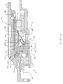
- FIG. 2 is a fragmentary side elevational view in full section of the FIG. 1 gas turbine engine having a carbon seal contaminant barrier system according to one embodiment of the present invention.
- FIG. 3 is a fragmentary side elevational view in full section of the FIG. 1 gas turbine engine having a carbon seal contaminant barrier according to another embodiment of the present invention.
- FIG. 4 is an end view of a baffle comprising a portion of the carbon seal contaminant barrier of FIG. 3.
- FIG. 5 is a side elevational view in full section of the FIG. 4 baffle.
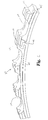
- FIG. 6 is an enlarged perspective view of a portion of the carbon sealing ring with pressurized fluid discharge aperture therein comprising a portion of the carbon seal contaminant barrier system.
- FIG. 1 there is illustrated a gas turbine engine 10 which includes a compressor 11, a combustor 12 and a power turbine 13.
- a gas turbine engine 10 which includes a compressor 11, a combustor 12 and a power turbine 13.
- Three components have been integrated together to produce an aircraft flight propulsion engine.
- One aircraft engine of this general type is model AE 2100 that is produced by Allison Engine Company, Inc. of Indianapolis, Indiana. It is important to realize that there are a multitude of ways in which the components can be linked together. Additional compressors and turbines could be added with intercoolers connected between the compressors and reheat combustion chambers could be added between the turbines.
- a gas turbine engine is equally well suited to be used for industrial applications. Historically, there has been wide spread application of industrial gas turbine engines, such as pumping sets for gas and oil transmission lines, electricity generation and naval propulsion.
- FIG. 2 there is illustrated a fragmentary view in full section of gas turbine engine 10.
- a tubular shaft 15 is rotatably mounted within the gas turbine engine 10 about a longitudinal axis y of the engine 10.
- the shaft 15 is supported on a plurality of bearings (only one illustrated) that are disposed between the shaft 15 and a rigid housing 17 that forms a portion of the engine 10.
- One of the plurality of bearings is a bearing 16 that is coupled to the mechanical housing 17.
- a volume defined between the shaft 15 and the mechanical housing 17 is sump 18 in which bearing 16 is disposed.
- the sump 18 functions as a reservoir for cooling fluid that is utilized to cool and lubricate the mechanical components of the gas turbine engine 10 such as bearing 16.
- annular barriers (not illustrated) are attached to the front and rear of the mechanical housing to close the sump 18.
- a plurality of seals are disposed between mechanical housing 17 and shaft 15 that is rotatably mounted within mechanical housing 17.
- One of the plurality of seals is sealing arrangement 21.
- the sealing arrangement 21 is a carbon seal system that includes a stationary component and a rotating component.
- the stationary component of the sealing arrangement 21 has a first sealing element 22 that is coupled to the mechanical housing 17. While the rotating component of the sealing arrangement 21 has a second sealing element 23 that is mechanically connected to the rotating shaft 15. It is well known that the rotating component of this sealing arrangement is known as a seal runner, and that the stationary component is known as a circumferential carbon seal. It is understood that other types of primary seals could also be used.
- first sealing element 22 is positioned axially concentric with and radially outward from the second sealing element 23. Further, in the preferred embodiment the sealing elements 22 and 23 are arranged adjacent to each other to form a rubbing interface therebetween.
- a first cylindrical surface 25 is formed on the radially inward side of the first sealing element 22, and a second cylindrical surface 26 is formed on the radially outward side of the second sealing element 23. At least a portion of the cylindrical surfaces 25 and 26 are maintained in rubbing contact to form a fluid tight seal at the rubbing interface 27.
- a lubrication system which normally provides cooling fluid under pressure to lubricate and cool the moving parts of the engine, such as the bearing 16 and the second sealing element 23 delivers its fluid through a nozzle 28.
- the cooling fluid is pressurized by a pump (not illustrated) to a pressure of about 30 pounds per square inch gage, and delivered through nozzle 28 with sufficient kinetic energy to traverse the passageway 30 formed along shaft 15.
- the passageway 30 provides a pathway for the axial flow of cooling fluid to a substantially solid planar surface 31 that forms a portion of the second sealing element 23. This planar surface 31 prevents any further axial flow of the cooling fluid and helps direct the fluid to flow in a substantially radial direction.
- a plurality of openings 39 are formed on one end of the passageway 30 to allow the discharge of cooling lubricants.
- the cooling fluid is an engine oil having a viscosity suited for the high temperatures associated with a gas turbine engine 10.
- Other types of fluid lubrication systems may be employed and the specific disclosure of the preferred embodiment is not intended to limit the types of lubrication systems which may be used in furtherance of the present invention.
- a circumferential channel 33 is formed on the radially inward surface 23a of the second sealing element 23.
- the radially inward surface 23a defines an outwardly sloping surface that is axially concentric with the first sealing element 22 and the second sealing element 23.
- This outwardly sloping surface preferably has a slope of about two degrees as measured from a reference line parallel to the central axis Y of the gas turbine engine 10.
- the circumferential channel 33 extends uninterrupted around the second sealing element 23.
- the channel 33 is designed and constructed for receiving cooling fluid therein that has been released through the plurality of openings 39 in passageway 30. As the cooling fluid exits the openings 39 of passageway 30 it is thrown radially outward by centrifugal forces during normal engine operation. As the cooling fluid is received into channel 33 it flows circumferentially through the channel until the channel is full. When the channel 33 is full of fluid it allows the cooling fluid to escape at a plurality of points along its length. The cooling fluid is evenly distributed on the radially inward surface 23a of the second sealing element 23 and provides for substantially uniform dissipation of thermal energy therefrom. Further details regarding a circumferential flow channel, such as flow channel 33 are disclosed in commonly owned U.S. Patent Application Serial No. 08/309,081, which is incorporated herein by reference.
- the second sealing element 23 has an external portion 8 extending a further distance from the first sealing element 22 than the channel 33 is located from the first sealing element 22. External portion 8 is designed to minimize the volume of oil that engages the first sealing element 22.
- the first sealing element 22 includes a carbon sealing element.
- the carbon sealing element defines an annular ring that is formed from a plurality of arcuate carbon material segments arranged in an abutting relationship.
- a windback 40 is positioned radially outward from the second sealing element 23 and adjacent the first sealing element 22. Windbacks are generally known to those skilled in the art, however, windback 40 has been designed and manufactured such that there is only one thread 41. The windback 40 is utilized to assist in preventing the impingement of oil onto the first sealing element 22.
- a fluid contaminant flow barrier 43 is disposed between the housing 17 and the rotating seal runner 23.
- the fluid contaminant flow barrier 43 is an annular baffle spaced radially from seal runner 23.
- the baffle 43 is formed of sheet metal. Baffle 43 (illustrated in FIGS. 5 and 6) is connected to the mechanical housing 17 and prevented from rotation relative to the housing by an anti-rotation mechanism.
- FIG. 3 there is illustrated a fragmentary side elevational view in section of a gas turbine engine having another embodiment of the carbon seal contaminant barrier system.
- FIGS. 2 and 3 are substantially identical with like numbers representing like features and distinctions therebetween will be discussed hereinafter.
- the fluid contaminant flow barrier 43 is positioned within the mechanical housing 17 by an interference fit.
- the fluid flow barrier 43 being radially spaced from seal runner 23 so as to eliminate contact between the seal runner 23 and the stationary barrier 43.
- An annular fluid seal 50 is disposed between the mechanical housing 17 and the outer cylindrical surface 23b of seal runner 23.
- the fluid seal 50 is a lip seal having a L-shaped lip and made of TEFLON® impregnated with carbon graphite.
- TEFLON® is a registered trademark of E.I. DuPont De Nemours and Company of Wilmington, DE.
- Other annular fluid seal designs are contemplated herein, such as a hydrodynamic lip and alternative material choices such as TEFLON® filled with glass/moly and TEFLON® filled with EKONOL®.
- EKONOL® is a trademark of Furon of Los Alamitos, CA.
- Other lip seals designs may be employed and the specific disclosure of lip seal 50 is not intended to limit the types of lip seals which may be used in furtherance of the present invention. However, it is understood that the lip seal must have the characteristics required to operate in the present environment.
- the lip 50a of the lip seal 50 rides on the outer cylindrical surface 23b of the seal runner 23 and wipes away solid oil that comes in contact therewith.
- a pressurized gas is discharged from the compressor through tubular shaft 15, aperture 100, aperture 101 in labryinth seal 102, and is delivered via a passageway adjacent to the face 53k of carbon sealing element 53.
- the discharge of the pressurized gas assists in preventing the impingement of contaminants on the carbon sealing element 53.
- the gaseous fluid is air.
- the discharge of the pressurized gas acts on the lip seal 50 in order to reduce the load associated with the lip seal 50 contacting the rotating seal runner 23. It is understood that as the engine speed increases, the pressurized gaseous supply increases.
- the corresponding reduction in the load associated with the lip seal 50 that is transferred to seal runner 53 decreases the incidence of the seals burning in a high speed rotary device such as a gas turbine engine 10.
- the pressurized gas also functions to blow contaminants away from the seal, and more particularly to blow oil away from the seal.
- pressurized gas from the compressor flows into a plurality of circumferential channels 110 formed on the planar face 111 of the arcuate carbon members 105.
- the gaseous flow from the compressor passes along the channels 110 formed on the individual carbon arcuate members 105 and is blocked from exiting the respective flow channel 105 by the adjoining arcuate carbon member and the mechanical housing 17.
- the planar surface 111 of the arcuate members 105 are in contact with an internal surface of the mechanical housing 17 and creates a fluid tight seal.
- a passageway 115 is formed across the planar sealing surface 111 at each of the respective joints where the respective arcuate carbon members 105 abut.
- the three passageways 115 allow the pressurized gas to flow between the respective abutting ends 120 and 121 of the members 105 and be discharged from the carbon ring adjacent surface 23b of the sealing element 23. Further, it is understood that in another embodiment of the present invention the carbon sealing element does not have apertures associated therewith for the pressurized discharge of gas adjacent the face of the carbon seal.
- Carbon sealing elements of this general type are now available from Stein Seal of Philadelphia, Pa. However, the utilization of pressurized gas to reduce the drag on lip seal 50 has been found to enhance the life of the seal.
- the circumferential carbon seal 53 is formed of three arcuate carbon members 105 (only 2 illustrated) that interlock and are assembled between the mechanical housing 17 and the shaft 15.
- a circumferential tensioning spring 106 is utilized to provide a compressive force to the plurality of arcuate carbon member 105 to position them adjacent and in rubbing interface with the rotating shaft 15.
- the fluid contaminant barrier 43 functions as a bulk head to prevent excited fluid from sump 18 from directly impinging onto the lip seal 50.
- the lubricant passes through the narrowed annular opening 125 it is calmed as it is discharged into an annular cavity 61.
- Annular cavity 61 is defined by lip seal 50, baffle 43, and the rotating shaft 15. The lubricant having been discharged into cavity 61 assists in cooling and lubricating the lip 50a of lip seal 50, thereby helping to prevent deterioration of lip seal due to the high surface speeds inherent in a gas turbine engine.
- fluid contaminant barrier 43 is a baffle with a central aperture disposed around sealing element 23, and a fluid drain aperture 75 which allows any fluid retained within cavity 61 to drain into the sump 18 after the gas turbine engine is shut down.
- the fluid drainage is a gravity fed process.
- the baffle 43 has an anti-rotation mechanism comprising a slot 76 that receives a pin (not illustrated) therein. The pin (not illustrated) is connected to the housing 17 and engages the anti-rotation slot 76 to prevent baffle 43 from rotating.
- the baffle 43 defines a annular ring having a first end 130 with a larger outside diameter d1 and a second end 131 with a smaller outside diameter d2 that are connected by a tapered cylindrical surface.
- Alternate forms of the present invention are contemplated herein and are deployable in different environments within a sump 18 located near a carbon seal.
- the two general classes of environment are classified as an air-oil mist environment and a solid oil environment. Owing to the characteristics of these two environments, each environment may require different methods to optimize the contaminant barrier sealing system, however there is no limitation intended that a specific contaminant barrier system design can only work in a specific class of environment.
- FIGS. 1-6 there will be illustrated examples of carbon seal contaminant barrier systems.
- a sump environment having substantially only air-oil mist there may be no need for the entire combination of baffle, lip seal and carbon seal with pressurized air discharge.
- the air-oil mist environment utilizing a contaminant barrier system without the baffle allows the air-oil mist to directly impinge upon the lip seal and cool the seal.
Landscapes
- Engineering & Computer Science (AREA)
- General Engineering & Computer Science (AREA)
- Mechanical Engineering (AREA)
- Turbine Rotor Nozzle Sealing (AREA)
- Sealing With Elastic Sealing Lips (AREA)
Applications Claiming Priority (2)
| Application Number | Priority Date | Filing Date | Title |
|---|---|---|---|
| US599028 | 1996-02-09 | ||
| US08/599,028 US5813830A (en) | 1996-02-09 | 1996-02-09 | Carbon seal contaminant barrier system |
Publications (3)
| Publication Number | Publication Date |
|---|---|
| EP0818607A2 true EP0818607A2 (de) | 1998-01-14 |
| EP0818607A3 EP0818607A3 (de) | 1999-04-28 |
| EP0818607B1 EP0818607B1 (de) | 2004-06-16 |
Family
ID=24397904
Family Applications (1)
| Application Number | Title | Priority Date | Filing Date |
|---|---|---|---|
| EP97300846A Expired - Lifetime EP0818607B1 (de) | 1996-02-09 | 1997-02-10 | Gasturbine mit Verunreinigungssperrsystem für Kohlenstoffdichtung |
Country Status (3)
| Country | Link |
|---|---|
| US (1) | US5813830A (de) |
| EP (1) | EP0818607B1 (de) |
| DE (1) | DE69729507D1 (de) |
Cited By (11)
| Publication number | Priority date | Publication date | Assignee | Title |
|---|---|---|---|---|
| EP1055848A1 (de) * | 1999-05-26 | 2000-11-29 | Techspace Aero | Dichtungsanordnung mit Auftrieb für Turbomaschinenlagergehäuse |
| EP1186813A1 (de) | 2000-09-07 | 2002-03-13 | Techspace Aero S.A. | Berührungsfreie Axialkohlenstoffdichtung für ein Lagergehäuse |
| EP1188972A1 (de) * | 2000-09-15 | 2002-03-20 | Techspace Aero S.A. | Berührungsfreie Axialkohlenstoffdichtung für ein Lagergehäuse |
| EP1262696A1 (de) | 2001-05-30 | 2002-12-04 | Techspace Aero S.A. | Dichtungsanordnung für Turbomaschinenlager |
| GB2473828A (en) * | 2009-09-24 | 2011-03-30 | Rolls Royce Plc | An oil seal assembly for a gas turbine engine |
| EP1777391A3 (de) * | 2005-10-19 | 2014-01-22 | General Electric Company | Gastubine und Methode über ihren Zusammenbau |
| WO2014138617A1 (en) | 2013-03-08 | 2014-09-12 | United Technologies Corporation | Fluid-cooled seal arrangement for a gas turbine engine |
| EP3348883A1 (de) * | 2016-09-22 | 2018-07-18 | MTU Aero Engines GmbH | Dichtungsanordnung für ein turbinenzwischengehäuse einer gasturbine |
| EP3954878A1 (de) * | 2020-08-14 | 2022-02-16 | Raytheon Technologies Corporation | Dichtungsläufer mit passiven wärmeübertragungserhöhungsmerkmalen |
| FR3114122A1 (fr) * | 2020-09-17 | 2022-03-18 | Safran Aircraft Engines | Turbine de turbomachine |
| EP4667349A1 (de) * | 2024-06-18 | 2025-12-24 | Pratt & Whitney Canada Corp. | Hybride propellerwellenlippen- und labyrinthdichtung |
Families Citing this family (34)
| Publication number | Priority date | Publication date | Assignee | Title |
|---|---|---|---|---|
| US6109615A (en) * | 1998-06-05 | 2000-08-29 | Skf Usa Inc. | Plenum oil seal |
| US6877950B2 (en) | 2001-11-29 | 2005-04-12 | Pratt & Whitney Canada Corp. | Method and device for minimizing oil consumption in a gas turbine engine |
| US7220098B2 (en) * | 2003-05-27 | 2007-05-22 | General Electric Company | Wear resistant variable stator vane assemblies |
| US7374301B1 (en) | 2005-02-20 | 2008-05-20 | Douglas Evan Simmers | Stretched membrane device |
| US7543992B2 (en) | 2005-04-28 | 2009-06-09 | General Electric Company | High temperature rod end bearings |
| US7410341B2 (en) * | 2005-06-22 | 2008-08-12 | Honeywell International, Inc. | Internally-cooled seal housing for turbine engine |
| US7905495B2 (en) * | 2007-11-29 | 2011-03-15 | Rolls-Royce Corporation | Circumferential sealing arrangement |
| US8490982B2 (en) * | 2008-05-22 | 2013-07-23 | Stein Seal Company | Windback device |
| WO2010062209A1 (en) * | 2008-11-28 | 2010-06-03 | Pratt & Whitney Canada Corp. | Oil cooled runner |
| US9359912B2 (en) * | 2011-01-10 | 2016-06-07 | United Technologies Corporation | Runner for circumferential seals |
| US8899924B2 (en) * | 2011-06-20 | 2014-12-02 | United Technologies Corporation | Non-mechanically fastened TOBI heat shield |
| CN102913621B (zh) | 2011-08-05 | 2015-11-25 | 哈米尔顿森德斯特兰德公司 | 碳密封件o型环腔尺寸设置 |
| US9373978B2 (en) | 2012-07-24 | 2016-06-21 | General Electric Company | Uninterruptible power supply apparatus for receiving power from different electrical utility configurations |
| US9896968B2 (en) | 2012-07-30 | 2018-02-20 | United Technologies Corporation | Forward compartment baffle arrangement for a geared turbofan engine |
| WO2014143097A1 (en) * | 2013-03-15 | 2014-09-18 | Stein Seal Company | Circumferential seal with ceramic runner |
| US9631508B2 (en) | 2013-06-13 | 2017-04-25 | Pratt & Whitney Canada Corp. | Internally cooled seal runner |
| US9476592B2 (en) | 2013-09-19 | 2016-10-25 | General Electric Company | System for injecting fuel in a gas turbine combustor |
| WO2015094463A1 (en) * | 2013-12-20 | 2015-06-25 | United Technologies Corporation | Seal runner |
| US10502094B2 (en) * | 2014-07-22 | 2019-12-10 | United Technologies Corporation | Bearing compartment sealing system with passive cooling |
| US9944399B2 (en) * | 2014-08-07 | 2018-04-17 | Pratt & Whitney Canada Corp. | Seal assembly for a bearing assembly in a gas turbine engine |
| US9896953B2 (en) | 2014-12-15 | 2018-02-20 | Pratt & Whitney Canada Corp. | Seal runner |
| US10753219B2 (en) | 2015-05-26 | 2020-08-25 | Pratt & Whitney Canada Corp. | Internally cooled seal runner and method of cooling seal runner of a gas turbine engine |
| US9989083B2 (en) * | 2015-05-26 | 2018-06-05 | Pratt & Whitney Canada Corp. | Seal and bearing assembly for a gas turbine engine and method of assembling same |
| DE102016211337A1 (de) * | 2016-06-24 | 2017-12-28 | MTU Aero Engines AG | Verdickter radial äußerer Ringbereich eines Dichtfins |
| EP4098845B1 (de) * | 2017-05-03 | 2025-03-05 | Stein Seal Company | Verbesserte umfangsdichtungsanordnung mit verstellbaren sitzkräften |
| US11085540B2 (en) * | 2018-11-30 | 2021-08-10 | Rolls-Royce Corporation | Circumferential air riding carbon seal on ceramic runner |
| US11255436B2 (en) | 2018-11-30 | 2022-02-22 | Rolls-Royce Corporation | Circumferential archbound carbon seal on ceramic runner |
| US11193590B2 (en) | 2019-01-14 | 2021-12-07 | Rolls-Royce Corporation | Seal assembly with buffered lip seal |
| US11299997B2 (en) * | 2019-08-21 | 2022-04-12 | Raytheon Technologies Corporation | Radial seal arrangement with axially elongated oil cooled runner |
| US11203948B2 (en) | 2019-09-06 | 2021-12-21 | Pratt & Whitney Canada Corp. | Seal runner and method |
| PL3798426T3 (pl) | 2019-09-27 | 2023-04-17 | Pratt & Whitney Canada Corp. | Zespół uszczelki węglowej |
| US11193389B2 (en) | 2019-10-18 | 2021-12-07 | Raytheon Technologies Corporation | Fluid cooled seal land for rotational equipment seal assembly |
| US11549444B2 (en) | 2021-02-05 | 2023-01-10 | Raytheon Technologies Corporation | Hybrid seal dual runner |
| FR3147593A1 (fr) * | 2023-04-07 | 2024-10-11 | Safran Transmission Systems | Boîtier de relais d’accessoires de turbomachine |
Family Cites Families (21)
| Publication number | Priority date | Publication date | Assignee | Title |
|---|---|---|---|---|
| US1937461A (en) * | 1930-10-25 | 1933-11-28 | Allen Sherman Hoff Co | Oil sealing device |
| US2451944A (en) * | 1942-01-21 | 1948-10-19 | Vickers Electrical Co Ltd | Axial flow compressor and like machines |
| US2598381A (en) * | 1949-07-06 | 1952-05-27 | Gen Electric | Vented shaft seal |
| US2956824A (en) * | 1957-12-27 | 1960-10-18 | Koppers Co Inc | Vented shaft seal |
| US2992842A (en) * | 1958-04-21 | 1961-07-18 | United Aircraft Corp | Oil scrubbed face seal |
| US3347553A (en) * | 1966-05-23 | 1967-10-17 | Gen Electric | Fluid seal |
| US3554661A (en) * | 1968-12-20 | 1971-01-12 | Decatur Pump Co | High temperature pump |
| US3806135A (en) * | 1972-10-04 | 1974-04-23 | Borg Warner | Cooling seal |
| US3955859A (en) * | 1975-03-25 | 1976-05-11 | The Torrington Company | Bearing with multiple lip seal |
| US4463956A (en) * | 1983-07-21 | 1984-08-07 | General Motors Corporation | Shield for labyrinth seal |
| US4613280A (en) * | 1984-09-21 | 1986-09-23 | Avco Corporation | Passively modulated cooling of turbine shroud |
| US4848776A (en) * | 1987-04-27 | 1989-07-18 | Eaton Corporation | Exclusion seal assembly |
| AU7741487A (en) * | 1987-08-25 | 1989-03-02 | Atsugi Motor Parts Company, Limited | Seal structure for rotary body and vane-type rotary compressor employing the same |
| US4917218A (en) * | 1989-04-03 | 1990-04-17 | General Motors Corporation | Secondary oil system for gas turbine engine |
| US4969652A (en) * | 1989-04-03 | 1990-11-13 | General Motors Corporation | Cooled shaft seal |
| US5018750A (en) * | 1989-06-02 | 1991-05-28 | Deere & Company | Shaft seal assembly |
| US5167487A (en) * | 1991-03-11 | 1992-12-01 | General Electric Company | Cooled shroud support |
| US5284347A (en) * | 1991-03-25 | 1994-02-08 | General Electric Company | Gas bearing sealing means |
| JP3074829B2 (ja) * | 1991-09-05 | 2000-08-07 | 松下電器産業株式会社 | 流体回転装置 |
| US5301957A (en) * | 1992-04-27 | 1994-04-12 | General Electric Company | Expanding circumferential seal with upper-cooled runner |
| US5272868A (en) * | 1993-04-05 | 1993-12-28 | General Electric Company | Gas turbine engine lubrication system |
-
1996
- 1996-02-09 US US08/599,028 patent/US5813830A/en not_active Expired - Lifetime
-
1997
- 1997-02-10 DE DE69729507T patent/DE69729507D1/de not_active Expired - Lifetime
- 1997-02-10 EP EP97300846A patent/EP0818607B1/de not_active Expired - Lifetime
Non-Patent Citations (1)
| Title |
|---|
| None |
Cited By (18)
| Publication number | Priority date | Publication date | Assignee | Title |
|---|---|---|---|---|
| EP1055848A1 (de) * | 1999-05-26 | 2000-11-29 | Techspace Aero | Dichtungsanordnung mit Auftrieb für Turbomaschinenlagergehäuse |
| EP1186813A1 (de) | 2000-09-07 | 2002-03-13 | Techspace Aero S.A. | Berührungsfreie Axialkohlenstoffdichtung für ein Lagergehäuse |
| EP1188972A1 (de) * | 2000-09-15 | 2002-03-20 | Techspace Aero S.A. | Berührungsfreie Axialkohlenstoffdichtung für ein Lagergehäuse |
| EP1262696A1 (de) | 2001-05-30 | 2002-12-04 | Techspace Aero S.A. | Dichtungsanordnung für Turbomaschinenlager |
| EP1777391A3 (de) * | 2005-10-19 | 2014-01-22 | General Electric Company | Gastubine und Methode über ihren Zusammenbau |
| GB2473828A (en) * | 2009-09-24 | 2011-03-30 | Rolls Royce Plc | An oil seal assembly for a gas turbine engine |
| GB2473828B (en) * | 2009-09-24 | 2011-08-10 | Rolls Royce Plc | Oil seal assembly |
| US8485531B2 (en) | 2009-09-24 | 2013-07-16 | Rolls-Royce, Plc | Oil seal assembly |
| WO2014138617A1 (en) | 2013-03-08 | 2014-09-12 | United Technologies Corporation | Fluid-cooled seal arrangement for a gas turbine engine |
| EP2964935A4 (de) * | 2013-03-08 | 2016-11-16 | United Technologies Corp | Flüssigkeitsgekühlte dichtungsanordnung für einen gasturbinenmotor |
| US10100672B2 (en) | 2013-03-08 | 2018-10-16 | United Technologies Corporation | Fluid-cooled seal arrangement for a gas turbine engine |
| US11066955B2 (en) | 2013-03-08 | 2021-07-20 | Raytheon Technologies Corporation | Fluid-cooled seal arrangement for a gas turbine engine |
| EP3348883A1 (de) * | 2016-09-22 | 2018-07-18 | MTU Aero Engines GmbH | Dichtungsanordnung für ein turbinenzwischengehäuse einer gasturbine |
| US10577959B2 (en) | 2016-09-22 | 2020-03-03 | MTU Aero Engines AG | Seal arrangement for a mid turbine frame of a gas turbine |
| EP3954878A1 (de) * | 2020-08-14 | 2022-02-16 | Raytheon Technologies Corporation | Dichtungsläufer mit passiven wärmeübertragungserhöhungsmerkmalen |
| US11274571B2 (en) | 2020-08-14 | 2022-03-15 | Raytheon Technologies Corporation | Seal runner with passive heat transfer augmentation features |
| FR3114122A1 (fr) * | 2020-09-17 | 2022-03-18 | Safran Aircraft Engines | Turbine de turbomachine |
| EP4667349A1 (de) * | 2024-06-18 | 2025-12-24 | Pratt & Whitney Canada Corp. | Hybride propellerwellenlippen- und labyrinthdichtung |
Also Published As
| Publication number | Publication date |
|---|---|
| EP0818607A3 (de) | 1999-04-28 |
| DE69729507D1 (de) | 2004-07-22 |
| US5813830A (en) | 1998-09-29 |
| EP0818607B1 (de) | 2004-06-16 |
Similar Documents
| Publication | Publication Date | Title |
|---|---|---|
| US5813830A (en) | Carbon seal contaminant barrier system | |
| JP3555683B2 (ja) | 回転機用シールアセンブリ | |
| US8657573B2 (en) | Circumferential sealing arrangement | |
| CA2544158C (en) | Integrated labyrinth and carbon seal | |
| US9909438B2 (en) | Hydrodynamic carbon face seal pressure booster | |
| US5593165A (en) | Circumferential flow channel for carbon seal runner cooling | |
| EP3318722B1 (de) | Dichtungsanordnung für ein drehbares bestandteil | |
| CN107120191A (zh) | 具有定心弹簧和挤压膜阻尼器的芯部差动轴承 | |
| US10920615B2 (en) | Self pressurizing squeeze film damper | |
| CN110056430B (zh) | 轴承共腔润滑与轴间封严装置及双转子航空发动机 | |
| WO1999064728A1 (en) | A system for delivering pressurized lubricant fluids to an interior of a rotating hollow shaft | |
| US4987795A (en) | Vented transmission | |
| EP3712469B1 (de) | Dichtungsplattenschmiermittelschleuderscheibe | |
| EP3453912B1 (de) | Selbstdruckbeaufschlagender quetschfilmdämpfer | |
| KR890004053B1 (ko) | 틈새형 시일(seal)조립체 | |
| US12270303B2 (en) | Seal assembly for a turbomachine | |
| US11143046B2 (en) | Seal runner and method | |
| US10670077B2 (en) | Sealed bearing assembly and method of forming same | |
| US10443443B2 (en) | Non-contacting seals for geared gas turbine engine bearing compartments | |
| US11181008B1 (en) | Self-pressurized squeeze film damper | |
| GB2366842A (en) | A bearing chamber sealing system | |
| EP3372793B1 (de) | Berührungslose dichtungen für lagerkammern eines verzahnten gasturbinenmotors | |
| US20250154879A1 (en) | Bearing assemblies for a turbomachine | |
| US20250198308A1 (en) | Cooling system for seal assemblies | |
| JPH01206165A (ja) | 円筒面シール |
Legal Events
| Date | Code | Title | Description |
|---|---|---|---|
| PUAI | Public reference made under article 153(3) epc to a published international application that has entered the european phase |
Free format text: ORIGINAL CODE: 0009012 |
|
| AK | Designated contracting states |
Kind code of ref document: A2 Designated state(s): DE FR GB |
|
| PUAL | Search report despatched |
Free format text: ORIGINAL CODE: 0009013 |
|
| AK | Designated contracting states |
Kind code of ref document: A3 Designated state(s): DE FR GB |
|
| 17P | Request for examination filed |
Effective date: 19990802 |
|
| 17Q | First examination report despatched |
Effective date: 20010921 |
|
| RAP1 | Party data changed (applicant data changed or rights of an application transferred) |
Owner name: ROLLS-ROYCE CORPORATION |
|
| RTI1 | Title (correction) |
Free format text: GAS TURBINE WITH CARBON SEAL CONTAINMENT BARRIER SYSTEM |
|
| GRAP | Despatch of communication of intention to grant a patent |
Free format text: ORIGINAL CODE: EPIDOSNIGR1 |
|
| GRAS | Grant fee paid |
Free format text: ORIGINAL CODE: EPIDOSNIGR3 |
|
| GRAA | (expected) grant |
Free format text: ORIGINAL CODE: 0009210 |
|
| AK | Designated contracting states |
Kind code of ref document: B1 Designated state(s): DE FR GB |
|
| PG25 | Lapsed in a contracting state [announced via postgrant information from national office to epo] |
Ref country code: FR Free format text: LAPSE BECAUSE OF NON-PAYMENT OF DUE FEES Effective date: 20040616 |
|
| REG | Reference to a national code |
Ref country code: GB Ref legal event code: FG4D |
|
| REF | Corresponds to: |
Ref document number: 69729507 Country of ref document: DE Date of ref document: 20040722 Kind code of ref document: P |
|
| PG25 | Lapsed in a contracting state [announced via postgrant information from national office to epo] |
Ref country code: DE Free format text: LAPSE BECAUSE OF FAILURE TO SUBMIT A TRANSLATION OF THE DESCRIPTION OR TO PAY THE FEE WITHIN THE PRESCRIBED TIME-LIMIT Effective date: 20040917 |
|
| PLBE | No opposition filed within time limit |
Free format text: ORIGINAL CODE: 0009261 |
|
| STAA | Information on the status of an ep patent application or granted ep patent |
Free format text: STATUS: NO OPPOSITION FILED WITHIN TIME LIMIT |
|
| 26N | No opposition filed |
Effective date: 20050317 |
|
| EN | Fr: translation not filed | ||
| PGFP | Annual fee paid to national office [announced via postgrant information from national office to epo] |
Ref country code: GB Payment date: 20160226 Year of fee payment: 20 |
|
| REG | Reference to a national code |
Ref country code: GB Ref legal event code: PE20 Expiry date: 20170209 |
|
| PG25 | Lapsed in a contracting state [announced via postgrant information from national office to epo] |
Ref country code: GB Free format text: LAPSE BECAUSE OF EXPIRATION OF PROTECTION Effective date: 20170209 |