EP0818637B1 - Unité de friction - Google Patents
Unité de friction Download PDFInfo
- Publication number
- EP0818637B1 EP0818637B1 EP97890113A EP97890113A EP0818637B1 EP 0818637 B1 EP0818637 B1 EP 0818637B1 EP 97890113 A EP97890113 A EP 97890113A EP 97890113 A EP97890113 A EP 97890113A EP 0818637 B1 EP0818637 B1 EP 0818637B1
- Authority
- EP
- European Patent Office
- Prior art keywords
- friction
- spherical segment
- ring
- friction surfaces
- axis
- Prior art date
- Legal status (The legal status is an assumption and is not a legal conclusion. Google has not performed a legal analysis and makes no representation as to the accuracy of the status listed.)
- Expired - Lifetime
Links
Images
Classifications
-
- F—MECHANICAL ENGINEERING; LIGHTING; HEATING; WEAPONS; BLASTING
- F16—ENGINEERING ELEMENTS AND UNITS; GENERAL MEASURES FOR PRODUCING AND MAINTAINING EFFECTIVE FUNCTIONING OF MACHINES OR INSTALLATIONS; THERMAL INSULATION IN GENERAL
- F16D—COUPLINGS FOR TRANSMITTING ROTATION; CLUTCHES; BRAKES
- F16D65/00—Parts or details
- F16D65/02—Braking members; Mounting thereof
-
- F—MECHANICAL ENGINEERING; LIGHTING; HEATING; WEAPONS; BLASTING
- F16—ENGINEERING ELEMENTS AND UNITS; GENERAL MEASURES FOR PRODUCING AND MAINTAINING EFFECTIVE FUNCTIONING OF MACHINES OR INSTALLATIONS; THERMAL INSULATION IN GENERAL
- F16D—COUPLINGS FOR TRANSMITTING ROTATION; CLUTCHES; BRAKES
- F16D23/00—Details of mechanically-actuated clutches not specific for one distinct type
- F16D23/02—Arrangements for synchronisation, also for power-operated clutches
- F16D23/025—Synchro rings
-
- F—MECHANICAL ENGINEERING; LIGHTING; HEATING; WEAPONS; BLASTING
- F16—ENGINEERING ELEMENTS AND UNITS; GENERAL MEASURES FOR PRODUCING AND MAINTAINING EFFECTIVE FUNCTIONING OF MACHINES OR INSTALLATIONS; THERMAL INSULATION IN GENERAL
- F16D—COUPLINGS FOR TRANSMITTING ROTATION; CLUTCHES; BRAKES
- F16D65/00—Parts or details
- F16D65/02—Braking members; Mounting thereof
- F16D2065/024—Braking members; Mounting thereof the braking surface being inclined with respect to the rotor's axis of rotation at an angle other than 90 degrees, e.g. comprising a conical rotor
Definitions
- the invention relates to a friction unit, in particular for synchronization devices of vehicle manual transmissions, with two essentially ring-shaped friction elements, which by relative movement to the torque transmitting Attachment to interacting friction surfaces can be brought.
- Arrangements of the type mentioned are known and enable, for example in clutches or brakes, or in particular in the synchronization devices mentioned of manual transmissions, a controlled, frictional Torque transmission.
- friction elements are known with essentially disc-shaped friction surfaces, but the disadvantage of one relatively high power requirement for pressing the friction surfaces together Transmission of a certain torque. This is why especially in the case of small-sized arrangements, friction elements have become common, where the cooperating friction surfaces are frustoconical, with suitable choice of the cone angle even with relatively low compression forces the required torque transmission can be ensured.
- annular friction elements are used as so-called synchronization rings for speed synchronization in described conical design used. These friction elements exist mostly from a carrier ring or support body made of brass or steel and a friction layer made of friction materials, such as organic friction linings or sintered rubbers. During the actual synchronization, the friction element with an inner and / or outer friction surface on one or two conical counter surface (s) pressed, thus the speed of the two to be synchronized Gear shafts are brought into line. This is in one Manual gearbox always required when changing from one gear to another another course.
- the present invention now based on the consideration that the conical design the actually interacting friction surfaces the basic There is a defect that occurs during the switching process or to initiate synchronization (which also applies to clutches, brakes or the like) the short actual due to a relatively narrow annular friction element Friction cone must be pushed onto the corresponding counter cone and can not be secured, so that a slight tilting of the two Cones to each other is possible. As a result, the two friction surfaces do not meet flatly in their entirety, so that relatively small, essentially sickle-shaped friction surface areas specifically much stronger be burdened or even overloaded. As a result, the congested Areas of increased wear.
- the synchronization device or generally reached the friction unit due to the bad Contact pattern does not meet the required frictional torque and ultimately fails.
- By the uneven load share ultimately becomes the load-bearing friction areas thermally stressed and damaged.
- reactions occur on the thermally overloaded friction areas, making a continuous overall decreasing coefficient of friction goes hand in hand.
- the present invention has the task of a uniform to allow frictional contact of the actual friction surfaces or a to rule out uneven positive locking.
- the constructive shape design should and the manufacturing process is correspondingly easy to implement.
- the above object is achieved with a friction unit
- the friction surfaces are each at least approximately are formed as the outer surface of a spherical layer, the center of which on the axis of the annular friction elements either in the ground level or lies outside the spherical layer. (Below ground level here and below the spherical layer boundary is on the larger side Understanding the opening of the annular friction element).
- Friction surfaces are therefore essentially formed as part of a spherical surface, with which tilting when bringing together in a very simple manner frictional interaction is excluded.
- the process for producing essentially ring-shaped friction elements, especially for synchronization devices of vehicle transmissions, where the friction surfaces as truncated cone surfaces with one for torque transmission selected cone angle and then calibrated is according to the invention characterized in that the friction surfaces in the calibration step are formed at least approximately as the outer surface of a spherical layer, the Center point on the axis of the annular friction elements either in the ground level or lies outside the spherical layer.
- the Friction surfaces as truncated cone surfaces with one chosen for torque transmission Cone angles are produced, for example, from AT 385 826 B or known from EP 292 468 A, with a possibly also simultaneously with the Forming calibration and final compression is described.
- the calibration step can, according to advantageous embodiments of the described Process either by grinding the friction surface, or with sintered Friction linings by embossing with the respective counter surface to the spherical surface embossing tool can be made.
- Scattered sintered friction lining can therefore grind the metallic friction surface accordingly and the sintered friction surface are embossed as described, being irrelevant is whether the basically conical shape of the friction lining before calibrating (as for example according to EP 292 468 A) or according to (as for example according to the above AT 385 826 B) the sintering of the friction lining is generated.
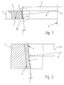
- FIG. 1 shows a partial axial section through an inventive Friction element from a total not shown here ....
- the friction unit shows the enlarged detail II from FIG. 1.
- the essentially annular friction element 1 has a carrier ring 2, for example made of steel or brass, which on its inner surface a scatter sintered friction lining 3 is provided.
- the actual friction surface 4 lies on the inner free surface of the friction lining 3 and has one basically conical alignment with respect to the axis 5 of the friction element 1, the cone angle Y taking into account the width Z and radius X of the friction surface 4 according to known and in connection with such arrangements usual calculation methods for the transmission of the torque is selected or calculated.
- the friction surface 4 is different from the pure truncated cone surface, such as it has approximately the wing 6 at the transition to the carrier ring 2, at least formed approximately as the outer surface of a spherical layer, the center of which M here at the intersection of the axis 5 of the friction element 1 with a vertical R to the cone angle Y selected for torque transmission in half Friction surface width (Z / 2) is.
- Cone angle Y is a position of the center M of the spherical layer in the point of penetration the axis 5 through the bottom plane of the spherical layer, which here with the upper limit of the friction element 1 shown coincides.
- the construction is at a ring height Z of 7.9 mm so designed that the radius of curvature of the friction surface Is 36 mm.
- the same radius of curvature is specified for the counter cone, which is made by grinding. Both parts, the friction ring and the counter cone, can with this constructive solution under a certain Angular range work without canting friction. It turned out dynamic coefficients of friction from 0.11 to 0.12, regardless of whether with mineral oil (e.g. SAE 75W-G14) or with synthetic oil (e.g. EGL 284). After 10,000 cycles, an axial path change of 0.08 to 0.12 mm was measured.
- the construction of the friction ring was designed with a ring height Z of 9.8 mm to a radius of curvature R of 50.015 mm outside and 45.004 mm inside (2x ring thickness subtracted).
- the angle Y of the tangent was 7 ° with this friction ring.
- the puncture point M for the radius of curvature was placed on the intersection of the perpendicular of the tangent and the ring axis S.
- the counter cones outside and inside were given the same radius of curvature.
- the friction ring has been tested for 10000 cycles in fully synthetic oil (e.g. BOT 72/94) and mineral oil (e.g. SAE 75W-GL4). Both tests showed a coefficient of friction of 0.105 to 0.115 and an axial travel change of 0.1 mm regardless of the specific axial force of 2 to 6 N / mm 2 . The change in axial travel took place within the first 2000 cycles and no change was detectable afterwards.
- the friction ring showed a uniform contact pattern on the outside and inside.
Landscapes
- Engineering & Computer Science (AREA)
- General Engineering & Computer Science (AREA)
- Mechanical Engineering (AREA)
- Mechanical Operated Clutches (AREA)
- Braking Arrangements (AREA)
Claims (4)
- Unité à friction, notamment pour des dispositifs de synchronisation de boítes de vitesses de véhicules, comportant deux éléments de friction (1) de forme essentiellement annulaire, qui peuvent être amenés sous l'effet d'un déplacement relatif à s'appliquer, en transmettant un couple, contre des surfaces de friction coopérantes (4), caractérisée en ce que les surfaces de friction (4) sont agencées chacune au moins approximativement sous la forme d'une surface enveloppe d'une couche sphérique, dont le centre (M) est situé sur l'axe (5) des éléments de friction (1) de forme sphérique soit dans le plan de base, soit à l'extérieur de la couche sphérique.
- Procédé pour fabriquer des éléments de friction (4) de forme essentiellement annulaire, notamment pour des dispositifs de synchronisation de boítes de vitesses de véhicules, selon lequel les éléments de friction (4) sont réalisés sous la forme de surfaces tronconiques possédant un angle de cône (Y) choisi pour la transmission du couple, et sont ensuite calibrés, caractérisé en ce que les surfaces de friction (4) sont réalisées, lors de l'étape de calibrage, au moins approximativement sous la forme d'une surface enveloppe d'une couche sphérique, dont le centre (M) est situé sur l'axe (5) des éléments de friction (1) de forme annulaire, soit dans le plan de base, soit à l'extérieur de la couche sphérique.
- Procédé selon la revendication 2, caractérisé en ce que l'étape de calibrage est réalisée par polissage de la surface de friction (4).
- Procédé selon la revendication 2, caractérisé en ce que l'étape de calibragé est réalisée, dans le cas de garnitures de friction formées par frittage (3), par gaufrage à l'aide d'un outil de gaufrage possédant la surface antagoniste respective correspondant à la surface enveloppe de la couche sphérique.
Applications Claiming Priority (3)
| Application Number | Priority Date | Filing Date | Title |
|---|---|---|---|
| AT1199/96 | 1996-07-08 | ||
| AT119996 | 1996-07-08 | ||
| AT0119996A AT403506B (de) | 1996-07-08 | 1996-07-08 | Reibeinheit |
Publications (2)
| Publication Number | Publication Date |
|---|---|
| EP0818637A1 EP0818637A1 (fr) | 1998-01-14 |
| EP0818637B1 true EP0818637B1 (fr) | 2001-09-05 |
Family
ID=3508759
Family Applications (1)
| Application Number | Title | Priority Date | Filing Date |
|---|---|---|---|
| EP97890113A Expired - Lifetime EP0818637B1 (fr) | 1996-07-08 | 1997-06-25 | Unité de friction |
Country Status (6)
| Country | Link |
|---|---|
| US (1) | US5918718A (fr) |
| EP (1) | EP0818637B1 (fr) |
| JP (1) | JPH1073131A (fr) |
| KR (1) | KR980010055A (fr) |
| AT (1) | AT403506B (fr) |
| DE (1) | DE59704513D1 (fr) |
Families Citing this family (8)
| Publication number | Priority date | Publication date | Assignee | Title |
|---|---|---|---|---|
| KR100692138B1 (ko) * | 2005-08-23 | 2007-03-12 | 현대자동차주식회사 | 자동 변속기용 클러치 |
| WO2010140412A1 (fr) * | 2009-06-04 | 2010-12-09 | 田中精密工業株式会社 | Matériau de frottement par glissement |
| US9695744B2 (en) | 2010-10-12 | 2017-07-04 | Ford Global Technologies, Llc | Engine drive system |
| DE102013000975A1 (de) * | 2013-01-22 | 2014-07-24 | Licos Trucktec Gmbh | "Reibschaltkupplung" |
| DE102015100869B4 (de) | 2015-01-21 | 2016-10-13 | Hoerbiger Antriebstechnik Holding Gmbh | Verfahren zur Herstellung eines Synchronrings sowie Synchronring für synchronisierte Schaltgetriebe |
| KR101994210B1 (ko) * | 2017-12-26 | 2019-06-28 | 현대트랜시스 주식회사 | 수동변속기용 싱크로나이저 링 |
| CN109780170A (zh) * | 2019-03-08 | 2019-05-21 | 重庆青山工业有限责任公司 | 汽车手动变速器同步环与接合齿圈的配合结构 |
| CN110877879A (zh) * | 2019-11-22 | 2020-03-13 | 成都凯天电子股份有限公司 | 自行式高空作业平台回转制动锁紧装置 |
Family Cites Families (9)
| Publication number | Priority date | Publication date | Assignee | Title |
|---|---|---|---|---|
| US191314A (en) * | 1877-05-29 | Improvement in friction-clutches | ||
| US686960A (en) * | 1901-04-01 | 1901-11-19 | John T Truitt | Frictional driving-gear. |
| US2354526A (en) * | 1940-02-07 | 1944-07-25 | Clark Equipment Co | Synchronizer and method of making the same |
| US3871944A (en) * | 1973-06-11 | 1975-03-18 | Minnesota Mining & Mfg | Integral composite element useful in electrostatic clutch or brake devices |
| DE2744994C2 (de) * | 1977-10-06 | 1985-08-29 | Stieber Division Der Borg-Warner Gmbh, 6900 Heidelberg | Verfahren zur Herstellung eines Synchronosierringes |
| DE3417813C1 (de) * | 1984-05-14 | 1985-06-05 | Sinterstahl GmbH, 8958 Füssen | Verwendung von Streusinter-Reibbelaegen in Reibkupplungen oder -bremsen |
| AT385826B (de) * | 1986-03-21 | 1988-05-25 | Hoerbiger & Co | Reibring fuer kupplungen oder bremsen, verfahren und vorrichtung zum herstellen des reibringes |
| DE3609879A1 (de) * | 1986-03-24 | 1987-10-08 | Hoerbiger & Co | Reibring fuer kupplungen oder bremsen, verfahren und vorrichtung zum herstellen des reibringes |
| AT387266B (de) * | 1987-05-20 | 1988-12-27 | Enfo Grundlagen Forschungs Ag | Reib- bzw. gleitkoerper, sowie verfahren und vorrichtung zu dessen herstellung |
-
1996
- 1996-07-08 AT AT0119996A patent/AT403506B/de not_active IP Right Cessation
-
1997
- 1997-06-25 EP EP97890113A patent/EP0818637B1/fr not_active Expired - Lifetime
- 1997-06-25 DE DE59704513T patent/DE59704513D1/de not_active Expired - Lifetime
- 1997-07-07 US US08/888,700 patent/US5918718A/en not_active Expired - Fee Related
- 1997-07-08 JP JP9182040A patent/JPH1073131A/ja active Pending
- 1997-07-21 KR KR1019970031409A patent/KR980010055A/ko not_active Withdrawn
Also Published As
| Publication number | Publication date |
|---|---|
| ATA119996A (de) | 1997-07-15 |
| JPH1073131A (ja) | 1998-03-17 |
| US5918718A (en) | 1999-07-06 |
| KR980010055A (ko) | 1998-04-30 |
| EP0818637A1 (fr) | 1998-01-14 |
| AT403506B (de) | 1998-03-25 |
| DE59704513D1 (de) | 2001-10-11 |
Similar Documents
| Publication | Publication Date | Title |
|---|---|---|
| DE2744994C2 (de) | Verfahren zur Herstellung eines Synchronosierringes | |
| EP0663536B1 (fr) | Rivet aveugle et méthode pour sa fabrication | |
| DE112009005177B4 (de) | Kraftübertragungszugmittel | |
| EP2459895B1 (fr) | Ensemble de bagues de synchronisation | |
| EP0521843B1 (fr) | Anneau de friction | |
| DE10139119A1 (de) | Drehmomentenfühler | |
| EP0818637B1 (fr) | Unité de friction | |
| DE4400431A1 (de) | Sinterreibwerkstoff für reibschlüssiges Element | |
| EP2181273B1 (fr) | Procede de fabrication d'un corps faisant partie d'un couple de friction, et corps faisant partie d'un couple de friction | |
| DE3705657A1 (de) | Reibring mit einer konischen oder zylindrischen reibflaeche | |
| DE19847139C1 (de) | Sperr-Synchronring für synchronisierte Schaltgetriebe | |
| DE19739469C2 (de) | Sicherheitskupplung | |
| AT407290B (de) | Reibkupplung oder bremse | |
| DE1085383B (de) | Getriebekette fuer Keilnutscheiben | |
| DE102005007647A1 (de) | Synchronisierungseinrichtung für ein Schaltgetriebe eines Kraftfahrzeuges | |
| DE102006023098B3 (de) | Mehrfach-Synchronisiereinheit für ein Schaltgetriebe | |
| DE102006030100B4 (de) | Schaltfinger für ein Getriebe-Betätigungsorgan | |
| DE19946706A1 (de) | Reibbelag | |
| DE102020108863A1 (de) | Druckstück für eine Synchronbaugruppe eines Fahrzeuggetriebes | |
| DE102007062467A1 (de) | Reibring | |
| DE102004016057A1 (de) | Mikrokonus-Kupplung | |
| DE4217948C1 (en) | Opening up surface pores on friction surfaces - by blasting surface with liq. or gas stream to remove bridging edges | |
| DE10055861A1 (de) | Reibring und Reibungskupplung | |
| EP3153732A1 (fr) | Anneau de friction pour une unité de synchronisation | |
| DE202007012150U1 (de) | Synchronring |
Legal Events
| Date | Code | Title | Description |
|---|---|---|---|
| PUAI | Public reference made under article 153(3) epc to a published international application that has entered the european phase |
Free format text: ORIGINAL CODE: 0009012 |
|
| AK | Designated contracting states |
Kind code of ref document: A1 Designated state(s): DE FR GB IT |
|
| 17P | Request for examination filed |
Effective date: 19980126 |
|
| AKX | Designation fees paid |
Free format text: DE FR GB IT |
|
| RBV | Designated contracting states (corrected) |
Designated state(s): DE FR GB IT |
|
| 17Q | First examination report despatched |
Effective date: 19990928 |
|
| GRAG | Despatch of communication of intention to grant |
Free format text: ORIGINAL CODE: EPIDOS AGRA |
|
| GRAG | Despatch of communication of intention to grant |
Free format text: ORIGINAL CODE: EPIDOS AGRA |
|
| GRAH | Despatch of communication of intention to grant a patent |
Free format text: ORIGINAL CODE: EPIDOS IGRA |
|
| GRAH | Despatch of communication of intention to grant a patent |
Free format text: ORIGINAL CODE: EPIDOS IGRA |
|
| GRAA | (expected) grant |
Free format text: ORIGINAL CODE: 0009210 |
|
| AK | Designated contracting states |
Kind code of ref document: B1 Designated state(s): DE FR GB IT |
|
| REF | Corresponds to: |
Ref document number: 59704513 Country of ref document: DE Date of ref document: 20011011 |
|
| GBT | Gb: translation of ep patent filed (gb section 77(6)(a)/1977) |
Effective date: 20011023 |
|
| REG | Reference to a national code |
Ref country code: GB Ref legal event code: IF02 |
|
| ET | Fr: translation filed | ||
| PLBE | No opposition filed within time limit |
Free format text: ORIGINAL CODE: 0009261 |
|
| STAA | Information on the status of an ep patent application or granted ep patent |
Free format text: STATUS: NO OPPOSITION FILED WITHIN TIME LIMIT |
|
| 26N | No opposition filed | ||
| PGFP | Annual fee paid to national office [announced via postgrant information from national office to epo] |
Ref country code: IT Payment date: 20080625 Year of fee payment: 12 |
|
| PGFP | Annual fee paid to national office [announced via postgrant information from national office to epo] |
Ref country code: FR Payment date: 20080522 Year of fee payment: 12 |
|
| PGFP | Annual fee paid to national office [announced via postgrant information from national office to epo] |
Ref country code: GB Payment date: 20080625 Year of fee payment: 12 |
|
| GBPC | Gb: european patent ceased through non-payment of renewal fee |
Effective date: 20090625 |
|
| REG | Reference to a national code |
Ref country code: FR Ref legal event code: ST Effective date: 20100226 |
|
| PG25 | Lapsed in a contracting state [announced via postgrant information from national office to epo] |
Ref country code: FR Free format text: LAPSE BECAUSE OF NON-PAYMENT OF DUE FEES Effective date: 20090630 |
|
| PG25 | Lapsed in a contracting state [announced via postgrant information from national office to epo] |
Ref country code: GB Free format text: LAPSE BECAUSE OF NON-PAYMENT OF DUE FEES Effective date: 20090625 |
|
| PG25 | Lapsed in a contracting state [announced via postgrant information from national office to epo] |
Ref country code: IT Free format text: LAPSE BECAUSE OF NON-PAYMENT OF DUE FEES Effective date: 20090625 |
|
| PGFP | Annual fee paid to national office [announced via postgrant information from national office to epo] |
Ref country code: DE Payment date: 20150831 Year of fee payment: 19 |
|
| REG | Reference to a national code |
Ref country code: DE Ref legal event code: R119 Ref document number: 59704513 Country of ref document: DE |
|
| PG25 | Lapsed in a contracting state [announced via postgrant information from national office to epo] |
Ref country code: DE Free format text: LAPSE BECAUSE OF NON-PAYMENT OF DUE FEES Effective date: 20170103 |