EP0818652A2 - Beleuchtungsleiste und Verfahren zur Herstellung - Google Patents
Beleuchtungsleiste und Verfahren zur Herstellung Download PDFInfo
- Publication number
- EP0818652A2 EP0818652A2 EP97110952A EP97110952A EP0818652A2 EP 0818652 A2 EP0818652 A2 EP 0818652A2 EP 97110952 A EP97110952 A EP 97110952A EP 97110952 A EP97110952 A EP 97110952A EP 0818652 A2 EP0818652 A2 EP 0818652A2
- Authority
- EP
- European Patent Office
- Prior art keywords
- strip
- conductor
- conductor strip
- lighting
- circuit board
- Prior art date
- Legal status (The legal status is an assumption and is not a legal conclusion. Google has not performed a legal analysis and makes no representation as to the accuracy of the status listed.)
- Granted
Links
Images


Classifications
-
- F—MECHANICAL ENGINEERING; LIGHTING; HEATING; WEAPONS; BLASTING
- F21—LIGHTING
- F21S—NON-PORTABLE LIGHTING DEVICES; SYSTEMS THEREOF; VEHICLE LIGHTING DEVICES SPECIALLY ADAPTED FOR VEHICLE EXTERIORS
- F21S2/00—Systems of lighting devices, not provided for in main groups F21S4/00 - F21S10/00 or F21S19/00, e.g. of modular construction
-
- B—PERFORMING OPERATIONS; TRANSPORTING
- B29—WORKING OF PLASTICS; WORKING OF SUBSTANCES IN A PLASTIC STATE IN GENERAL
- B29C—SHAPING OR JOINING OF PLASTICS; SHAPING OF MATERIAL IN A PLASTIC STATE, NOT OTHERWISE PROVIDED FOR; AFTER-TREATMENT OF THE SHAPED PRODUCTS, e.g. REPAIRING
- B29C45/00—Injection moulding, i.e. forcing the required volume of moulding material through a nozzle into a closed mould; Apparatus therefor
- B29C45/14—Injection moulding, i.e. forcing the required volume of moulding material through a nozzle into a closed mould; Apparatus therefor incorporating preformed parts or layers, e.g. injection moulding around inserts or for coating articles
- B29C45/14639—Injection moulding, i.e. forcing the required volume of moulding material through a nozzle into a closed mould; Apparatus therefor incorporating preformed parts or layers, e.g. injection moulding around inserts or for coating articles for obtaining an insulating effect, e.g. for electrical components
- B29C45/14655—Injection moulding, i.e. forcing the required volume of moulding material through a nozzle into a closed mould; Apparatus therefor incorporating preformed parts or layers, e.g. injection moulding around inserts or for coating articles for obtaining an insulating effect, e.g. for electrical components connected to or mounted on a carrier, e.g. lead frame
-
- F—MECHANICAL ENGINEERING; LIGHTING; HEATING; WEAPONS; BLASTING
- F21—LIGHTING
- F21S—NON-PORTABLE LIGHTING DEVICES; SYSTEMS THEREOF; VEHICLE LIGHTING DEVICES SPECIALLY ADAPTED FOR VEHICLE EXTERIORS
- F21S4/00—Lighting devices or systems using a string or strip of light sources
- F21S4/20—Lighting devices or systems using a string or strip of light sources with light sources held by or within elongate supports
- F21S4/22—Lighting devices or systems using a string or strip of light sources with light sources held by or within elongate supports flexible or deformable, e.g. into a curved shape
- F21S4/24—Lighting devices or systems using a string or strip of light sources with light sources held by or within elongate supports flexible or deformable, e.g. into a curved shape of ribbon or tape form, e.g. LED tapes
-
- F—MECHANICAL ENGINEERING; LIGHTING; HEATING; WEAPONS; BLASTING
- F21—LIGHTING
- F21V—FUNCTIONAL FEATURES OR DETAILS OF LIGHTING DEVICES OR SYSTEMS THEREOF; STRUCTURAL COMBINATIONS OF LIGHTING DEVICES WITH OTHER ARTICLES, NOT OTHERWISE PROVIDED FOR
- F21V23/00—Arrangement of electric circuit elements in or on lighting devices
- F21V23/06—Arrangement of electric circuit elements in or on lighting devices the elements being coupling devices, e.g. connectors
-
- F—MECHANICAL ENGINEERING; LIGHTING; HEATING; WEAPONS; BLASTING
- F21—LIGHTING
- F21S—NON-PORTABLE LIGHTING DEVICES; SYSTEMS THEREOF; VEHICLE LIGHTING DEVICES SPECIALLY ADAPTED FOR VEHICLE EXTERIORS
- F21S8/00—Lighting devices intended for fixed installation
- F21S8/02—Lighting devices intended for fixed installation of recess-mounted type, e.g. downlighters
- F21S8/022—Lighting devices intended for fixed installation of recess-mounted type, e.g. downlighters intended to be recessed in a floor or like ground surface, e.g. pavement or false floor
-
- F—MECHANICAL ENGINEERING; LIGHTING; HEATING; WEAPONS; BLASTING
- F21—LIGHTING
- F21S—NON-PORTABLE LIGHTING DEVICES; SYSTEMS THEREOF; VEHICLE LIGHTING DEVICES SPECIALLY ADAPTED FOR VEHICLE EXTERIORS
- F21S8/00—Lighting devices intended for fixed installation
- F21S8/02—Lighting devices intended for fixed installation of recess-mounted type, e.g. downlighters
- F21S8/024—Lighting devices intended for fixed installation of recess-mounted type, e.g. downlighters intended to be recessed in a wall or like vertical structure, e.g. building facade
-
- F—MECHANICAL ENGINEERING; LIGHTING; HEATING; WEAPONS; BLASTING
- F21—LIGHTING
- F21Y—INDEXING SCHEME ASSOCIATED WITH SUBCLASSES F21K, F21L, F21S and F21V, RELATING TO THE FORM OR THE KIND OF THE LIGHT SOURCES OR OF THE COLOUR OF THE LIGHT EMITTED
- F21Y2103/00—Elongate light sources, e.g. fluorescent tubes
- F21Y2103/10—Elongate light sources, e.g. fluorescent tubes comprising a linear array of point-like light-generating elements
-
- F—MECHANICAL ENGINEERING; LIGHTING; HEATING; WEAPONS; BLASTING
- F21—LIGHTING
- F21Y—INDEXING SCHEME ASSOCIATED WITH SUBCLASSES F21K, F21L, F21S and F21V, RELATING TO THE FORM OR THE KIND OF THE LIGHT SOURCES OR OF THE COLOUR OF THE LIGHT EMITTED
- F21Y2115/00—Light-generating elements of semiconductor light sources
- F21Y2115/10—Light-emitting diodes [LED]
-
- Y—GENERAL TAGGING OF NEW TECHNOLOGICAL DEVELOPMENTS; GENERAL TAGGING OF CROSS-SECTIONAL TECHNOLOGIES SPANNING OVER SEVERAL SECTIONS OF THE IPC; TECHNICAL SUBJECTS COVERED BY FORMER USPC CROSS-REFERENCE ART COLLECTIONS [XRACs] AND DIGESTS
- Y10—TECHNICAL SUBJECTS COVERED BY FORMER USPC
- Y10S—TECHNICAL SUBJECTS COVERED BY FORMER USPC CROSS-REFERENCE ART COLLECTIONS [XRACs] AND DIGESTS
- Y10S362/00—Illumination
- Y10S362/80—Light emitting diode
Definitions
- the invention relates to a lighting strip with a multi-core Conductor strip, the one with LED elements arranged one behind the other is equipped.
- a lighting strip of the aforementioned type is shown in EP-0 669 492 A1.
- a conductor strip is provided which a so-called "Kaplan film". It is one with one Metal coating provided plastic strips, in which the conductor tracks are exposed by etching away metal coating areas.
- Conductor strips are illuminants at predetermined intervals, hereinafter briefly called LED elements, soldered on.
- the production of the conductor strips is based on a relatively expensive technology and requires many steps and requires the use of high quality materials.
- Foil strips provided with conductor tracks usually have a coating provided, there have been sealing problems in practice and it has It has been shown that the film strip is difficult, especially in corner areas can be misplaced (risk of kinking) and is also quite sensitive to scratching.
- the invention has for its object to provide it with a conductor strip, which should be simple and inexpensive to manufacture and assemble and which is characterized by great functional reliability.
- LED elements are equipped in that the conductor strip from a variety of cut to length, in the axial direction contiguous conductor strip sections that each between two axially adjacent conductor strip sections one with these electrically connected printed circuit board is arranged and that each circuit board is equipped with an LED element.
- the lighting strip according to the invention provides that the individual wires of the conductor strip are covered with insulation are that the insulation at the end areas of each conductor strip section is removed and that the connection between the respective end a conductor strip section and the respective circuit board via electrical conductive contact elements is made, between the contact elements and the wires of the conductor strip section each have a crimp connection and between the contact elements and the conductor tracks of the circuit board one rivet connection is provided.
- the lighting strip according to the invention provides that the individual wires of the conductor strip are covered with insulation are that the insulation at the end areas of each conductor strip section is removed and that the connection between the respective end a conductor strip section and the respective circuit board via electrical conductive contact elements is made, between the contact elements and the wires of the conductor strip section each have a crimp connection and between the contact elements and the conductor tracks of the circuit board one rivet connection is provided.
- the end areas the conductor strip sections, the contact elements, the circuit boards and the LED elements each in one only the light exit side of the LED elements free colored, formed by direct molding Encapsulated in plastic housing.
- Another preferred embodiment of the invention can consist in that the end regions of the conductor strip sections, the contact elements, the Printed circuit boards and the LED elements each in one by direct Overmoulding with a transparent plastic material, such as polycarbonate, formed plastic housing are encapsulated. With this measure there is no need to keep the light exit side of the LED elements clear. Of further training can thereby be realized in that each Plastic housing on the light exit side of the LED elements molded material approach to the appropriate intervention in a corresponding cover openings provided cover of Has lighting bar. So there is the possibility of a cover a lighting strip from the start with in a row openings, such as holes, to be provided or already convert existing moldings, such as plinths, stair moldings or the like, by covering these strips with any hole pattern provides.
- a transparent plastic material such as polycarbonate
- a first measure provides that the conductor strip consists of individual each has an insulation wire
- a second Measure provides that the conductor strip in the manner of a flexible flat cable is trained. In both cases, you can use commercially available wires or Flat cables that can be used without any problems, even in difficult transition points or corner areas because of their high flexibility have it installed.
- Another embodiment of the invention provides instead that the conductor strip from an extruded, relatively dimensionally stable profile strip with it stored wires. It is then possible that the profile bar is designed as a clip strip and / or adhesive strip. These measures are useful for relatively rigid systems and then bring the special one The advantage that the conductor strips can be installed without additional aids or have it fastened and do not require any additional cover.
- the plastic housing an approximately rectangular contour with molded on the longitudinal edges Clip strips, clip lugs or the like for clip mounting of the conductor strip in a receiving channel formed within the lighting strip having.
- the lighting strip according to the invention is further characterized in that that the conductor strip in a receiving channel from a cover strip opaque material is arranged for the passage of the LED elements perforations formed in series one behind the other that the Conductor strips and the cover strip a pre-assembled installation unit for Arrangement in a receiving channel of the lighting strip is and that this Installation unit by a, which also engages in the receiving channel here friction and / or positively held Abehlußprofilance from one transparent plastic material is covered and kept in a position-oriented manner.
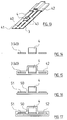
- the invention can be applied to a lighting strip with a multi-core Conductor strip, the one with LED elements arranged one behind the other is equipped, also realize that the conductor strip from one There is copper tape, the veins of which are punched and cut from each other are separated and that the conductor strip including the mounted LED elements, resistors and the like from an extruded thereon surrounded by a transparent plastic material formed tube profile is.
- a conductor or light strip also has an absolute Tightness
- Embodiment is given according to the one with a lighting bar multi-core conductor strip, the one with the row in a row LED elements is equipped, it is provided that the conductor strip a plastic film tape, copper tapes laminated on it and mounted LED elements, resistors and the like. and from one extruded thereon, formed from a transparent plastic material Hose profile exists.
- the tube profile can be on the underside equipped with a double-sided adhesive tape provided with a protective film to attach the conductor strip in the corresponding receiving channel to simplify the lighting bar.
- the lighting strip according to the invention can in particular be used as a handrail, Stair tread, luggage compartment, plinth or escape route marker strip designed be.
- a method of making an insulated, multi-core conductor strip with LED elements arranged in a row for a lighting strip is characterized according to the invention in that a conductor strip section finite length in conductor strip sections of predetermined length is divided and that at the respectively axially adjacent end regions of the Conductor strip sections one each, with an LED element and possibly with a printed circuit board is connected. It can Cutting a conductor strip section to length and connecting a circuit board each take place intermittently.
- the circuit board of an extrusion coating station fed and here as well as the end areas of those connected to the circuit board Overmoulded conductor with plasticized transparent plastic material becomes. This measure is also particularly advantageous in terms of on avoiding sealing problems and for using lighting strips a cover strips having a row of holes.
- the seventh step a method step is arranged in which a flexible cover strip supplied from a supply roll and with the Conductor strips and / or is connected to the circuit boards.
- the measure be taken after the sixth step and / or after the encapsulation of each printed circuit board Functional test is carried out.
- Fig. 1 shows a lighting bar for use as a bottom bar 1.
- the lighting bar but can also be used as a handrail, stair step, luggage compartment, Skirting or escape route marking bar may be formed.
- the lighting bar generally consists of aluminum or an aluminum alloy, can of course also be made of a plastic material.
- a receiving channel 2 of the lighting strip is a multi-core conductor strip 3, with the LED elements arranged in series 4 is assembled.
- the receiving channel 2 is up through a End profile strip 5 closed from a transparent material.
- the End profile bar 5 is z. B. made of polycarbonate.
- FIG. 2 is a lighting strip for use as a base or wall strip 6 shown.
- This bar also has a receiving channel 2 and one multi-core conductor strips 3, which are arranged in series with one another LED elements 4 is populated.
- the skirting or wall strip 6 is made also made of aluminum, an aluminum alloy or plastic, what also applies to the end profile strip 7, which with openings 8 for Light emission is provided.
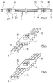
- Fig. 3 shows a multi-core conductor strip 3, which consists of a variety of cut conductor strip sections strung together in the axial direction 9 and arranged between the conductor strip sections 9 and with these there are electrically conductively connected printed circuit boards 10, which in conventional Way with conductor tracks, not shown, for. B. in the manner of a Printed circuit is provided and carries an LED element connected to it 4 and possibly a resistor 12 (see FIG. 7).
- the number of wires the conductor strip 3 is arbitrary and depends on the desired Type of lighting, such as permanent illumination or, if necessary, running light.
- FIG. 3 is five-wire, there is the conductor strip 3 according to FIGS. 4 and 5 each of three wires. You can the conductor strips 3, as shown in Fig. 4, each one Insulating wires 13 or, as shown in Fig. 4 according to Art a flexible flat cable 14 may be formed. In both cases the Conductor strips 3 divided into conductor strip sections 9 and these are with their end regions each to an at least one LED element 4 Printed circuit board 10 connected.
- a conductor strip 3 from an extruded, relatively dimensionally stable profile strip 15 with insulated or embedded therein to form non-insulated conductor wires and then in conductor strip sections 9 split.
- This possibility shown in FIG. 6 has the advantage To be able to form 3 clip lugs 16 onto the conductor strips for the purpose of being easier Clip fastening of the conductor strip 3 in the receiving channel 2 of the respective Lighting bar.
- the profile bar 15 can be provided with a bottom Double adhesive tape 17 be equipped so that the profile bar 15 after the Peel off a protective film 18 glued to the bottom of the receiving channel 2 can be. 6 also change profile strip sections 15 and with LED elements 4 printed circuit boards 10 from each other.
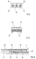
- FIG. 7 shows the cable assembly with a printed circuit board 10.
- a printed circuit board 10 For example are three wires 13 in different colors, e.g. B. red for positive pole black for negative pole and white for middle conductor and electrically conductive with the circuit board 10 connected.
- the individual wires 13 of each Conductor strip section 9 can also be a flat cable 14 according to FIG. 5 or a Profile bar 15 are provided according to FIG. 6.
- Fig. 7 carries the circuit board 10, an LED element 4 and a resistor 12.
- the cable assembly by means of electrical contact elements 19 is preferred manufactured, whereby - cf. also FIG. 8 - between the contact elements 19 and the wires of the wires 13 each have a crimp connection 20 and between the contact elements 19 and the conductor tracks of the printed circuit board 10 - cf. also Fig. 9 - a rivet connection 21 is provided in each case.
- the above Connections 20, 21 are also clearly shown in the longitudinal section Fig. 10 can be seen.
- this unit for a simple embodiment of a Lighting strip that does not waterproof the electrical seal Requires joints, brought together with a cover strip 22 shown in FIG. 11.
- the cover strip 22 has a narrowed by locking lugs 23 Channel 24 on which allows the circuit board 10 to be clipped in.
- the cover strip 22 has openings 25 arranged one behind the other to pass the LED elements 4 on. 11 can now in a receiving channel 2 a z. B. introduced baseboard 1 and supported by the self-locking end profile strip 5 and are held, as shown in Fig. 1.
- Plastic housing 26 are encapsulated.
- the plastic housing 26 is in the Fig. 7 to 10 shown and can also be molded with integrally molded clip strips 27 for fastening arrangement in a cover strip 22 (cf. also FIG. 11) be trained.
- the plastic housing 26 can also consist of a transparent material and also encapsulate the light exit side of the LED elements 4, wherein it is recommended to use the light exit sides of the individual LED elements 4 each have a material approach (not shown in more detail) for the appropriate intervention to be formed in the receiving openings 8 of the end profile strip 7 (FIG. 2).
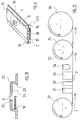
- a manufacturing facility shown in Fig. 12 can carry out the method for producing a lighting strip for a lighting strip of the example shown in FIGS. 1 and 2 Kind.
- a supply roll 30 is used Conductor strips 3 of finite length removed and a trimming station 31 fed.
- the trimming station 31 is equipped with tools that the Subdivide conductor strips 3 by cutting into conductor strip sections 9, then around the mutually adjacent end regions of conductor strips 3 and strip strip section 9.
- the tools hold the stripped End areas firmly and move so far apart that in a feed station 32 first the contact elements 19 to the stripped end regions for the purpose of establishing a crimp connection 20 and to the supplied Printed circuit board 10 struck in order to produce a riveted joint 21 can be.
- the cutting station 31 and feed station 32 coincide spatially or also spatially from one another be separated.
- the circuit board 10 supplied in each case is at least one preassembled LED element 4 but possibly also with a preassembled one Resistor 12 equipped.
- the electrically connected to the cable ends Printed circuit board 10 is transported on and an extrusion coating station 33 fed.
- the circuit board is then in the encapsulation station 33 10 as well as the contact elements 19 and the end regions of the to Printed circuit board 10 connected conductor with plasticized plastic material encapsulated.
- the light exit side of the LED element 4 kept clear of the plastic material while a complete encapsulation and encapsulation is provided when a transparent, translucent plastic material is used.
- the Injection molding station 33 follows a control station 34, in which a 100% Light control is carried out. After the light control, the lighting strip a cover strip 22 fed from a supply roll 35. There is a latching z. B. with the clip strips 27 of the plastic housing 26. After that, the completed lighting strip is placed on a Magazine roll 36 wound up and for laying in the receiving channel 2 a lighting bar ready. With lighting strips with In terms of tightness, the requirement profile can be encapsulated omitted, while in lighting strips with 15 formed from profile strips Conductor strip sections 9 on feeding a separate cover strip 22 can be dispensed with.
- connection between the respective End of a conductor strip section 9 and the respective circuit board 10 over to produce electrically conductive contact elements 19 and between the contact elements 19 and the wires of the conductor strip section 9 each Crimp connection 20 and between the contact elements 19 and the conductor tracks the circuit board 10 each has to provide a riveted connection 21 proved to be beneficial.
- one is special rational, reliable and inexpensive electrical connection between the respective end of a conductor strip section 9 and the respective circuit board 10 by soldering, brazing or in particular also Welding can be produced with the advantage of saving components and work steps.
Landscapes
- Engineering & Computer Science (AREA)
- General Engineering & Computer Science (AREA)
- Manufacturing & Machinery (AREA)
- Mechanical Engineering (AREA)
- Led Device Packages (AREA)
- Fastening Of Light Sources Or Lamp Holders (AREA)
- Illuminated Signs And Luminous Advertising (AREA)
- Decoration Of Textiles (AREA)
- Lighting Device Outwards From Vehicle And Optical Signal (AREA)
Abstract
Description
- Fig. 1
- eine erste Ausführungsform einer Beleuchtungsleiste,
- Fig. 2
- eine zweite Ausführungsform einer Beleuchtungsleiste,
- Fig. 3
- einen Leiterstreifen mit Leuchtmitteln,
- Fig. 4 - 6
- verschiedene Ausführungsformen eines Leiterstreifens,
- Fig. 7
- einen Anschlußbereich zwischen Leiterstreifen und Leiterplatte in Draufsicht,
- Fig. 8
- einen Schnitt etwa folgend der Linie VIII - VIII in Fig. 7,
- Fig. 9
- einen Schnitt etwa folgend der Linie IX - IX in Fig. 7,
- Fig. 10
- einen Schnitt etwa folgend der Linie X - X in Fig. 7,
- Fig. 11
- einen Schnitt durch eine Leiterplatten-Abdeckleisten-Verbindung,
- Fig. 12
- eine schematische Darstellung des Herstellungsverfahrens,
- Fig. 13 - 15
- eine andere Ausführungsform eines Leiterstreifens mit Leuchtmitteln und
- Fig. 16 - 17
- eine noch andere Ausführungsform eines Leiterstreifens mit Leuchtmitteln.
Claims (23)
- Beleuchtungsleiste mit einem mehradrigen Leiterstreifen (3), der mit in Reihe hintereinander angeordneten LED-Elementen (4) bestückt ist, dadurch gekennzeichnet, daß der Leiterstreifen (3) aus einer Vielzahl von abgelängten, in axialer Richtung aneinandergereihten Leiterstreifenabschnitten (9) besteht, daß jeweils zwischen zwei axial aneinandergrenzenden Leiterstreifenabschnitten (9) eine mit diesen elektrisch leitend verbundene Leiterplatte (10) angeordnet ist, und daß jede Leiterplatte (10) mit einem LED-Element (4) bestückt ist.
- Beleuchtungsleiste nach Anspruch 1, dadurch gekennzeichnet, daß die einzelnen Adern des Leiterstreifens (3) mit einer Isolierung umhüllt sind, daß die Isolierung an den Endbereichen jedes Leiterstreifenabschnitts (9) entfernt ist und daß die Verbindung zwischen dem jeweiligen Ende eines Leiterstreifenabschnitts (9) und der jeweiligen Leiterplatte (10) über elektrisch leitende Kontaktelemente (19) hergestellt ist, wobei zwischen den Kontaktelementen (19) und den Adern des Leiterstreifenabschnitts (9) jeweils eine Crimpverbindung (20) und zwischen den Kontaktelementen (19) und den Leiterbahnen der Leiterplatte (10) jeweils eine Nietverbindung (21) vorgesehen ist.
- Beleuchtungsleiste nach Anspruch 1 oder 2, dadurch gekennzeichnet, daß die Endbereiche der Leiterstreifenabschnitte (9), die Kontaktelemente (19), die Leiterplatten (10) und die LED-Elemente (4) jeweils in einem nur die Lichtaustrittsseite der LED-Elemente (4) freilassenden, durch unmittelbares Umspritzen gebildetes farbiges Kunststoffgehäuse (26) eingekapselt sind.
- Beleuchtungsleiste nach Anspruch 1 oder 2, dadurch gekennzeichnet, daß die Endbereiche der Leiterstreifenabschnitt (9), die Kontaktelemente (19), die Leiterplatten (10) und die LED-Elemente (4) jeweils in einem durch unmittelbares Umspritzen mit einem transparenten Kunststoffmaterial, wie Polycarbonat, gebildetes Kunststoffgehäuse (26) eingekapselt sind.
- Beleuchtungsleiste nach Anspruch 4, dadurch gekennzeichnet, daß jedes Kunststoffgehäuse (26) an der Lichtaustrittsseite der LED-Elemente (4) einen angeformten Materialansatz zum passenden Eingriff in eine mit entsprechenden Aufnahmeöffnungen (8) versehene Abdeckung (7) der Beleuchtungsleiste aufweist.
- Beleuchtungsleiste nach wenigstens einem der Ansprüche 1 bis 5, dadurch gekennzeichnet, daß der Leiterstreifen (3) aus einzelnen jeweils eine Isolierung aufweisenden Drähten (13) besteht.
- Beleuchtungsleiste nach wenigstens einem der Ansprüche 1 bis 5, dadurch gekennzeichnet, daß der Leiterstreifen (3) nach Art eines flexiblen Flachkabels (14) ausgebildet ist.
- Beleuchtungsleiste nach wenigstens einem der Ansprüche 1 bis 5, dadurch gekennzeichnet, daß der Leiterstreifen (3) aus einer extrudierten, relativ formstabilen Profilleiste (15) mit darin eingelagerten Drähten besteht.
- Beleuchtungsleiste nach Anspruch 8, dadurch gekennzeichnet, daß die Profilleiste (15) als Klipsleiste und/oder Klebeleiste ausgebildet ist.
- Beleuchtungsleiste nach wenigstens einem der Ansprüche 1 bis 9, dadurch gekennzeichnet, daß das Kunststoffgehäuse (26) eine etwa rechteckige Kontur mit an den Längsrändern angeformten Klipsleisten, Klipsnasen (16) oder dgl. für eine Klipsmontage des Leiterstreifens (3) in einem innerhalb der Beleuchtungsleiste ausgebildeten Aufnahmekanal (2) aufweist.
- Beleuchtungsleiste nach einem oder mehreren der vorangegangenen Ansprüche, dadurch gekennzeichnet, daß der Leiterstreifen (3) in einem Aufnahmekanal (24) einer Abdeckleiste (22) aus undurchsichtigem Material angeordnet ist, die zum Durchtritt der LED-Elemente (4) in Reihe hintereinander ausgebildete Lochungen (25) aufweist, daß der Leiterstreifen (3) und die Abdeckleiste (22) eine vorkonfektionierte Einbaueinheit zur Anordnung in einem Aufnahmekanal (2) der Beleuchtungsleiste ist und daß diese Einbaueinheit durch eine, ebenfalls in den Aufnahmekanal (2) eingreifende und hier kraft- und/oder formschlüssig gehaltene Abschlußprofilleiste (5) aus einem transparenten Kunststoffmaterial überdeckt und lageorientiert gehalten ist.
- Beleuchtungsleiste mit einem mehradrigen Leiterstreifen (3), der mit in Reihe hintereinander angeordneten LED-Elementen (4) bestückt ist, dadurch gekennzeichnet, daß der Leiterstreifen (3) aus einem Kupferband (40) besteht, dessen Adern durch Stanz- und Freischnitte (41, 43) voneinander getrennt sind und daß der Leiterstreifen (3) einschließlich der aufmontierten LED-Elemente (4), Widerstände (12) und dgl. von einem darauf aufextrudierten, aus einem transparenten Kunststoffmaterial gebildeten Schlauchprofil (42) umgeben ist.
- Beleuchtungsleiste mit einem mehradrigen Leiterstreifen (3), der mit in Reihe hintereinander angeordneten LED-Elementen (4) bestückt ist, dadurch gekennzeichnet, daß der Leiterstreifen (3) aus einem Folienband (50), darauf aufkaschierten Kupferbändern (51) und aufmontierten LED-Elementen (4), Widerständen (12) und dgl. sowie aus einem darauf aufextrudierten aus einem transparenten Kunststoffmaterial gebildeten Schlauchprofil (52) besteht.
- Beleuchtungsleiste nach zumindest einem der vorhergehenden Ansprüche, gestaltet als Handlauf-, Treppenstufen-, Gepäckfach-, Sockel- oder Fluchtwegmarkierungsleiste.
- Verfahren zum Herstellen eines isolierten mehradrigen Leiterstreifens (3) mit in Reihe hintereinander angeordneten LED-Elementen (4) für eine Beleuchtungsleiste, dadurch gekennzeichnet, daß ein Leiterstreifen (3) endlicher Länge in Leiterstreifenabschnitte (9) vorbestimmter Länge unterteilt wird und daß an den jeweils axial benachbarten Endbereichen der Leiterstreifenabschnitte (9) jeweils eine mit einem LED-Element (4) und ggf. mit einem Widerstand (12) bestückte Leiterplatte (10) angeschlossen wird.
- Verfahren nach Anspruch 15, dadurch gekennzeichnet, daß das Ablängen eines Leiterstreifenabschnitts (9) und das Anschließen einer Leiterplatte (10) jeweils intermittierend erfolgt.
- Verfahren nach Anspruch 15 und 16 mit den sich jeweils intermittierend wiederholenden Verfahrensschritten:1. Abziehen eines Leiterstreifens (3) endlicher Länge von einer Vorratsrolle (30) und Zuführen zu einer Beschneidestation (31),2. Ablängen eines Leiterstreifenabschnitts (9) vorbestimmter Länge vom Leiterstreifen (3) endlicher Länge und Festhalten des Leiterstreifenabschnitts (9) mit einer Haltevorrichtung,3. Abisolieren der einander benachbarten Endbereiche von Leiterstreifen (3) und Leiterstreifenabschnitt (9),4. Positionieren der abisolierten Endbereiche,5. Zuführen einer mit zumindest einem LED-Element (4) bestückten Leiterplatte (10),6. Herstellen einer elektrischen Verbindung zwischen den abisolierten Endbereichen und den Leiterbahnen der Leiterplatte (10),7. Weiterleiten des über die Leiterplatte (10) wieder mit dem Leiterstreifen (3) verbundenen Leiterstreifenabschnitts (9) zu einer Aufwickeltrommel (36).
- Verfahren nach Anspruch 17, dadurch gekennzeichnet, daß die Verfahrensschritte zwei, drei und vier gleichzeitig in der Beschneidestation (31) durchgeführt werden.
- Verfahren nach Anspruch 17 oder 18, dadurch gekennzeichnet, daß zwischen dem sechsten und siebenten Verfahrensschritt die Leiterplatte (10) einer Umspritzungsstation (33) zugeführt und hier ebenso wie die Endbereiche der an die Leiterplatte (10) angeschlossenen Leiter mit plastifiziertem farbigem Kunststoffmaterial umspritzt wird, wobei die Lichtaustrittsseite des LED-Elements (4) vom Umspritzungsmaterial freigehalten wird.
- Verfahren nach Anspruch 17 oder 18, dadurch gekennzeichnet, daß zwischen dem sechsten und siebenten Verfahrensschritt die Leiterplatte (10) einer Umspritzungsstation zugeführt und hier ebenso wie die Endbereiche der an der Leiterplatte (10) angeschlossenen Leiter mit plastifiziertem transparentem Kunststoffmaterial umspritzt wird.
- Verfahren nach einem oder mehreren der vorangegangenen Ansprüche, dadurch gekennzeichnet, daß dem siebenten Verfahrensschritt ein Verfahrensschritt vorgeordnet ist, bei dem dem Leiterstreifen (3) eine flexible Abdeckleiste (22) von einer Vortatsrolle (35) her zugeführt und mit dem Leiterstreifen (3) und/oder mit den Leiterplatten (10) verbunden wird.
- Verfahren nach einem oder mehreren der vorangegangenen Ansprüche, dadurch gekennzeichnet, daß nach dem sechsten Verfahrensschritt und/oder nach dem Umspritzen einer jeden Leiterplatte (10) eine Funktionsprüfung erfolgt.
- Beleuchtungsleiste insbesondere nach Anspruch 1, dadurch gekennzeichnet, daß die einzelnen Adern des Leiterstreifens (3) mit einer Isolierung umhüllt sind, daß die Isolierung an den Endbereichen jedes Leiterstreifenabschnitts (9) entfernt ist und daß zwischen dem jeweiligen Ende eines Leiterstreifenabschnitts (9) und den Leiterbahnen der Leiterplatte (10) eine Lot-, Hartlöt- oder Schweißverbindung vorgesehen ist.
Priority Applications (1)
| Application Number | Priority Date | Filing Date | Title |
|---|---|---|---|
| TW086113651A TW488197B (en) | 1996-07-11 | 1997-09-19 | Lighting strip and method for production |
Applications Claiming Priority (2)
| Application Number | Priority Date | Filing Date | Title |
|---|---|---|---|
| DE19627856 | 1996-07-11 | ||
| DE19627856A DE19627856A1 (de) | 1996-07-11 | 1996-07-11 | Beleuchtungsleiste und Verfahren zur Herstellung |
Publications (3)
| Publication Number | Publication Date |
|---|---|
| EP0818652A2 true EP0818652A2 (de) | 1998-01-14 |
| EP0818652A3 EP0818652A3 (de) | 1998-04-29 |
| EP0818652B1 EP0818652B1 (de) | 2002-12-18 |
Family
ID=7799478
Family Applications (1)
| Application Number | Title | Priority Date | Filing Date |
|---|---|---|---|
| EP97110952A Expired - Lifetime EP0818652B1 (de) | 1996-07-11 | 1997-07-02 | Beleuchtungsleiste und Verfahren zur Herstellung |
Country Status (7)
| Country | Link |
|---|---|
| US (1) | US6074074A (de) |
| EP (1) | EP0818652B1 (de) |
| KR (1) | KR100392981B1 (de) |
| DE (2) | DE19627856A1 (de) |
| ES (1) | ES2188825T3 (de) |
| HU (1) | HU224144B1 (de) |
| SG (1) | SG67985A1 (de) |
Cited By (17)
| Publication number | Priority date | Publication date | Assignee | Title |
|---|---|---|---|---|
| WO2000055541A1 (es) * | 1999-03-16 | 2000-09-21 | Friedemann Hoffmann | Dispositivo de señalizacion luminosa para suelos |
| DE19904915A1 (de) * | 1999-02-06 | 2001-02-01 | Alcatel Sa | Feuchtigkeitsdichtes Lichtband |
| WO2004023033A1 (en) | 2002-09-06 | 2004-03-18 | Koninklijke Philips Electronics N.V. | Led assembly |
| DE102006011594A1 (de) * | 2006-03-10 | 2007-09-13 | Mross Jun., Ulrich | Beleuchtungsvorrichtung |
| WO2007134963A1 (de) * | 2006-05-18 | 2007-11-29 | Osram Gesellschaft mit beschränkter Haftung | Anordnung für eine elektrische leitungsführung für led-leuchten |
| WO2008115983A1 (en) | 2007-03-19 | 2008-09-25 | Lumination Llc | Sealed lighting units |
| WO2008125480A1 (de) * | 2007-04-12 | 2008-10-23 | BSH Bosch und Siemens Hausgeräte GmbH | Flachbandkabelbeleuchtung für ein wasserführendes haushaltsgerät |
| WO2010092106A1 (de) * | 2009-02-13 | 2010-08-19 | Osram Gesellschaft mit beschränkter Haftung | Leuchtmodul und verfahren zum herstellen eines leuchtmoduls |
| WO2010124951A3 (de) * | 2009-04-30 | 2010-12-29 | Saint-Gobain Glass France | Scheibenanordnung mit beleuchtung durch led-lichtleiste und herstellungsverfahren |
| WO2010089218A3 (de) * | 2009-02-04 | 2011-01-06 | Osram Gesellschaft mit beschränkter Haftung | Leuchtmodul |
| EP2543922A1 (de) * | 2011-07-04 | 2013-01-09 | Thomas Gmür Gmbh | Lichtleiste |
| DE102012214333A1 (de) * | 2012-08-10 | 2014-03-06 | Protektorwerk Florenz Maisch Gmbh & Co. Kg | Profilelement |
| AT13894U1 (de) * | 2013-04-03 | 2014-11-15 | Tridonic Gmbh & Co Kg | LED - Kette |
| CN105101610A (zh) * | 2014-05-20 | 2015-11-25 | 广东德豪润达电气股份有限公司 | 软性电路板及具有该软性电路板的led软灯带 |
| WO2017098383A1 (en) * | 2015-12-10 | 2017-06-15 | Osram Gmbh | A casing for lighting devices, corresponding device and method |
| WO2020182573A1 (de) | 2019-03-14 | 2020-09-17 | Volkswagen Aktiengesellschaft | Beleuchtungseinheit für ein kraftfahrzeug |
| CN115812341A (zh) * | 2020-07-09 | 2023-03-17 | 昕诺飞控股有限公司 | 照明带 |
Families Citing this family (127)
| Publication number | Priority date | Publication date | Assignee | Title |
|---|---|---|---|---|
| FI108106B (fi) * | 1996-11-25 | 2001-11-15 | Modular Technology Group Engin | Menetelmä johde-elementin valmistamiseksi ja johde-elementti |
| US6720745B2 (en) | 1997-08-26 | 2004-04-13 | Color Kinetics, Incorporated | Data delivery track |
| US6965205B2 (en) | 1997-08-26 | 2005-11-15 | Color Kinetics Incorporated | Light emitting diode based products |
| DE19857718C2 (de) * | 1997-12-18 | 2002-07-11 | Carmen-Katja Pollmann | Niedervolt-Beleuchtungssystem |
| DE29803477U1 (de) * | 1998-03-03 | 1998-07-09 | P.E.R. Flucht- und Rettungsleitsysteme GmbH, 22885 Barsbüttel | Vorrichtung zur Ausbildung aktiv leuchtender Leuchtwegesysteme |
| USD445211S1 (en) | 2000-06-08 | 2001-07-17 | Media Technology Source, Inc. | Theater aisle lighting extrusion |
| US7202613B2 (en) | 2001-05-30 | 2007-04-10 | Color Kinetics Incorporated | Controlled lighting methods and apparatus |
| US7303300B2 (en) | 2000-09-27 | 2007-12-04 | Color Kinetics Incorporated | Methods and systems for illuminating household products |
| DE10106961A1 (de) * | 2001-02-15 | 2002-08-29 | Happich Fahrzeug & Ind Teile | Bleuchtungseinrichtung |
| US6739735B2 (en) * | 2001-09-20 | 2004-05-25 | Illuminated Guidance Systems, Inc. | Lighting strip for direction and guidance systems |
| US6566824B2 (en) * | 2001-10-16 | 2003-05-20 | Teledyne Lighting And Display Products, Inc. | Flexible lighting segment |
| US6997575B2 (en) * | 2002-01-29 | 2006-02-14 | Gelcore Llc | Apparatus and manufacturing method for border lighting |
| DE20203326U1 (de) | 2002-03-01 | 2002-07-04 | Hansen, Hans-Thomas, 25855 Haselund | LED-Beleuchtung |
| CN100547282C (zh) * | 2002-04-25 | 2009-10-07 | 林原 | 可挠性发光体装置及其制造方法 |
| US7063440B2 (en) * | 2002-06-03 | 2006-06-20 | Everbrite, Llc | LED accent lighting units |
| US7300192B2 (en) | 2002-10-03 | 2007-11-27 | Color Kinetics Incorporated | Methods and apparatus for illuminating environments |
| US6678171B1 (en) | 2002-10-24 | 2004-01-13 | Guide Corporation | Fastening arrangement for light emitting diode metal array |
| DE20300976U1 (de) | 2003-01-17 | 2003-04-03 | Brandau, Jonas, 10407 Berlin | Niederspannungsdekorationsleuchte mit weißen SMD-LEDs |
| ES2934308T3 (es) | 2003-05-05 | 2023-02-21 | Signify North America Corp | Unidad de iluminación |
| PL201463B1 (pl) * | 2003-05-19 | 2009-04-30 | Andrzej Szymański | Oprawa liniowego źródła światła |
| US7128438B2 (en) * | 2004-02-05 | 2006-10-31 | Agilight, Inc. | Light display structures |
| US7144139B2 (en) * | 2004-03-10 | 2006-12-05 | Kramer Eric W | Flexible surface lighting system |
| CN1998112A (zh) * | 2004-10-08 | 2007-07-11 | 滕波工业公司 | 发光照明系统和方法 |
| US20060146529A1 (en) * | 2005-01-04 | 2006-07-06 | Hsin-Yin Ho | Plastic light emitting band |
| US8305225B2 (en) * | 2005-02-14 | 2012-11-06 | Truck-Lite Co., Llc | LED strip light lamp assembly |
| JP2006256003A (ja) * | 2005-03-16 | 2006-09-28 | Honda Motor Co Ltd | 構造板 |
| DE102005027371B4 (de) * | 2005-06-14 | 2009-12-10 | Ursula Denschlag | Leuchtelementen-Bausatz |
| US7520771B2 (en) | 2005-07-13 | 2009-04-21 | Lumination Llc | LED string light engine and devices that are illuminated by the string light engine |
| US7160140B1 (en) | 2005-07-13 | 2007-01-09 | Gelcore Llc | LED string light engine |
| DE102005039651B4 (de) * | 2005-08-22 | 2008-04-03 | Airbus Deutschland Gmbh | Illumination im Bereich von Flugzeugkabinen |
| US8465175B2 (en) | 2005-11-29 | 2013-06-18 | GE Lighting Solutions, LLC | LED lighting assemblies with thermal overmolding |
| DE102006018668B4 (de) * | 2006-04-21 | 2013-04-11 | Osram Gmbh | Modulares Beleuchtungssystem und Beleuchtungsanordnung |
| US20080007418A1 (en) * | 2006-06-26 | 2008-01-10 | Maki Brian E | Proximity-triggered handrail cueing system with automatic attention capture |
| DE102006031345A1 (de) * | 2006-07-06 | 2008-01-10 | Patent-Treuhand-Gesellschaft für elektrische Glühlampen mbH | Formflexibles Beleuchtungssystem |
| US8807796B2 (en) | 2006-09-12 | 2014-08-19 | Huizhou Light Engine Ltd. | Integrally formed light emitting diode light wire and uses thereof |
| US8052303B2 (en) | 2006-09-12 | 2011-11-08 | Huizhou Light Engine Ltd. | Integrally formed single piece light emitting diode light wire and uses thereof |
| PL2061991T3 (pl) * | 2006-09-12 | 2011-08-31 | Paul Lo | Integralnie utworzony jednoelementowy przewód świetlny z diod elektroluminescencyjnych |
| US8567992B2 (en) * | 2006-09-12 | 2013-10-29 | Huizhou Light Engine Ltd. | Integrally formed light emitting diode light wire and uses thereof |
| US7815341B2 (en) * | 2007-02-14 | 2010-10-19 | Permlight Products, Inc. | Strip illumination device |
| US20080239716A1 (en) * | 2007-03-30 | 2008-10-02 | Yuan Lin | Light strip |
| US20090104804A1 (en) * | 2007-10-23 | 2009-04-23 | Jeff Lin | Led metal strip flexible interconnection |
| CN201121811Y (zh) * | 2007-11-09 | 2008-09-24 | 邵树发 | 可任意安排造型之线条灯 |
| US20090147509A1 (en) * | 2007-12-07 | 2009-06-11 | Reed Daniel P | Configurable led lighting strip |
| US8118447B2 (en) | 2007-12-20 | 2012-02-21 | Altair Engineering, Inc. | LED lighting apparatus with swivel connection |
| US7832896B2 (en) * | 2008-04-18 | 2010-11-16 | Lumination Llc | LED light engine |
| US8177392B2 (en) * | 2008-05-29 | 2012-05-15 | Norm Tarko | Light strip including a core layer of insulating material receiving spaced apart light emitting diodes |
| US7938562B2 (en) | 2008-10-24 | 2011-05-10 | Altair Engineering, Inc. | Lighting including integral communication apparatus |
| US8901823B2 (en) | 2008-10-24 | 2014-12-02 | Ilumisys, Inc. | Light and light sensor |
| US8653984B2 (en) | 2008-10-24 | 2014-02-18 | Ilumisys, Inc. | Integration of LED lighting control with emergency notification systems |
| US8214084B2 (en) | 2008-10-24 | 2012-07-03 | Ilumisys, Inc. | Integration of LED lighting with building controls |
| CN100588870C (zh) * | 2008-11-07 | 2010-02-10 | 深圳市贝晶光电科技有限公司 | 一种led线条灯 |
| CN101769469B (zh) * | 2008-12-31 | 2011-10-12 | 佳必琪国际股份有限公司 | 发光二极管灯条及其制造方法 |
| CN101813263B (zh) * | 2009-02-20 | 2012-02-01 | 深圳市科利尔照明科技有限公司 | 一种制作灯带的方法及灯带 |
| US8474998B2 (en) | 2010-03-08 | 2013-07-02 | Ge Lighting Solutions Llc | Rail and clip mounting for LED modules for fluorescent application replacement |
| WO2011119958A1 (en) | 2010-03-26 | 2011-09-29 | Altair Engineering, Inc. | Inside-out led bulb |
| US8444287B2 (en) * | 2010-06-16 | 2013-05-21 | Gary Lawrence Hardesty | Lighted flooring |
| WO2012058556A2 (en) | 2010-10-29 | 2012-05-03 | Altair Engineering, Inc. | Mechanisms for reducing risk of shock during installation of light tube |
| USD649690S1 (en) * | 2011-01-04 | 2011-11-29 | LEDs ON | Extrusion for LED-based lighting apparatus |
| USD649682S1 (en) * | 2011-01-04 | 2011-11-29 | LEDs ON | Extrusion for LED-based lighting apparatus |
| USD649689S1 (en) * | 2011-01-04 | 2011-11-29 | LEDs ON | Extrusion for LED-based lighting apparatus |
| USD649687S1 (en) * | 2011-01-04 | 2011-11-29 | LEDs ON | Extrusion for LED-based lighting apparatus |
| USD649691S1 (en) * | 2011-01-04 | 2011-11-29 | LEDs ON | Extrusion for LED-based lighting apparatus |
| USD649680S1 (en) * | 2011-01-04 | 2011-11-29 | LEDs ON | Extrusion for light emitting diode based lighting apparatus |
| USD649686S1 (en) * | 2011-01-04 | 2011-11-29 | LEDs ON | Extrusion for LED-based lighting apparatus |
| USD649684S1 (en) * | 2011-01-04 | 2011-11-29 | LEDs ON | Extrusion for LED-based lighting apparatus |
| USD651739S1 (en) * | 2011-01-04 | 2012-01-03 | LEDs ON | Extrusion for LED-based lighting apparatus |
| USD649692S1 (en) * | 2011-01-04 | 2011-11-29 | LEDs ON | Extrusion for LED-based lighting apparatus |
| KR101032928B1 (ko) | 2011-01-07 | 2011-05-06 | 메코시스 주식회사 | 미디어 파사드 루버장치 |
| USD652569S1 (en) * | 2011-02-15 | 2012-01-17 | LEDs ON | Extrusion for LED-based lighting apparatus |
| USD652986S1 (en) * | 2011-03-25 | 2012-01-24 | LEDs ON | Extrusion for LED-based lighting apparatus |
| USD652568S1 (en) * | 2011-03-25 | 2012-01-17 | LEDs ON | Extrusion for LED-based lighting apparatus |
| USD652985S1 (en) * | 2011-05-13 | 2012-01-24 | LEDs ON | Extrusion for LED-based lighting apparatus |
| USD649681S1 (en) * | 2011-06-15 | 2011-11-29 | LEDsON | Extrusion for LED-based lighting apparatus |
| USD649683S1 (en) * | 2011-06-15 | 2011-11-29 | LEDs ON | Extrusion for LED-based lighting apparatus |
| USD649685S1 (en) * | 2011-06-19 | 2011-11-29 | LEDs ON | Extrusion for LED-based lighting apparatus |
| USD649688S1 (en) * | 2011-06-19 | 2011-11-29 | LEDs ON | Extrusion for LED-based lighting apparatus |
| USD649693S1 (en) * | 2011-06-20 | 2011-11-29 | LEDs ON | Extrusion for LED-based lighting apparatus |
| US9072171B2 (en) * | 2011-08-24 | 2015-06-30 | Ilumisys, Inc. | Circuit board mount for LED light |
| USD662255S1 (en) * | 2011-11-04 | 2012-06-19 | Klus Sylwester | External housing for LED-based linear lighting apparatus |
| USD662256S1 (en) * | 2011-11-04 | 2012-06-19 | Klus Sylwester | External housing for LED-based linear lighting apparatus |
| US8702284B2 (en) * | 2012-02-08 | 2014-04-22 | Lun An Pan Enterprise Co., Ltd. | Vehicle running board |
| US9117991B1 (en) * | 2012-02-10 | 2015-08-25 | Flextronics Ap, Llc | Use of flexible circuits incorporating a heat spreading layer and the rigidizing specific areas within such a construction by creating stiffening structures within said circuits by either folding, bending, forming or combinations thereof |
| JP5927682B2 (ja) * | 2012-04-19 | 2016-06-01 | フィリップス ライティング ホールディング ビー ヴィ | Ledグリッド装置、及びledグリッド装置を製造する方法 |
| CN103511995B (zh) * | 2012-06-29 | 2016-04-20 | 展晶科技(深圳)有限公司 | 发光二极管灯条 |
| US9271367B2 (en) | 2012-07-09 | 2016-02-23 | Ilumisys, Inc. | System and method for controlling operation of an LED-based light |
| US20140111982A1 (en) * | 2012-10-18 | 2014-04-24 | GE Lighting Solutions, LLC | Tape-on retrofit leds for fluorescent troffers |
| US9285084B2 (en) | 2013-03-14 | 2016-03-15 | Ilumisys, Inc. | Diffusers for LED-based lights |
| US9464780B2 (en) | 2013-03-15 | 2016-10-11 | General Led, Inc. | LED light engine for signage |
| US9626884B2 (en) | 2013-03-15 | 2017-04-18 | General Led, Inc. | LED light engine for signage |
| US10217387B2 (en) | 2013-03-15 | 2019-02-26 | General Led Opco, Llc | LED light engine for signage |
| TWI509186B (zh) * | 2013-09-06 | 2015-11-21 | 隆達電子股份有限公司 | 全周光型發光單元及發光裝置及全周光型發光單元的製作方法 |
| WO2015049726A1 (ja) * | 2013-10-01 | 2015-04-09 | トヨタ自動車株式会社 | 空燃比センサの異常診断装置 |
| US9267650B2 (en) | 2013-10-09 | 2016-02-23 | Ilumisys, Inc. | Lens for an LED-based light |
| WO2015112437A1 (en) | 2014-01-22 | 2015-07-30 | Ilumisys, Inc. | Led-based light with addressed leds |
| US9777908B1 (en) * | 2014-02-27 | 2017-10-03 | Amazon Technologies, Inc. | Strut channel recessed lighting fixture |
| US9644836B1 (en) * | 2014-03-28 | 2017-05-09 | Itasca Plastics, Inc | Lighted handrail assembly |
| DE102014104433A1 (de) * | 2014-03-28 | 2015-10-01 | Döllken-Kunststoffverarbeitung Gmbh | Verfahren und Vorrichtung zum Bearbeiten eines LED-Streifens |
| US9510400B2 (en) | 2014-05-13 | 2016-11-29 | Ilumisys, Inc. | User input systems for an LED-based light |
| DE102015005285A1 (de) | 2015-04-25 | 2016-10-27 | Happich Gmbh | Beleuchtungsleiste |
| EP3093552B1 (de) * | 2015-05-12 | 2021-02-17 | OSRAM GmbH | Verbindungsvorrichtung für eine leuchte und entsprechendes verfahren |
| US10161568B2 (en) | 2015-06-01 | 2018-12-25 | Ilumisys, Inc. | LED-based light with canted outer walls |
| CN105172089A (zh) * | 2015-10-16 | 2015-12-23 | 中山市欧曼科技照明有限公司 | 一种led柔性灯带的生产方法 |
| US10077897B2 (en) * | 2016-03-03 | 2018-09-18 | David R. Hall | Toilet with an LED diffuser strip |
| USD799066S1 (en) | 2016-05-13 | 2017-10-03 | Qtran, Inc. | Corner extrusion |
| USD798471S1 (en) | 2016-05-13 | 2017-09-26 | Qtran, Inc. | Multi-level extrusion |
| USD799065S1 (en) | 2016-05-13 | 2017-10-03 | Qtran, Inc. | Extrusion |
| US9741273B1 (en) | 2016-08-10 | 2017-08-22 | Jeffrey A. Curtis | Illuminated assemblies and methods of manufacture thereof |
| US10845034B2 (en) * | 2017-09-05 | 2020-11-24 | AVID Labs, LLC | Lighting system |
| US10731804B2 (en) * | 2018-01-24 | 2020-08-04 | Carl Boehmer | Traffic control system with flexible LED lighted assembly |
| US10823366B2 (en) | 2018-03-14 | 2020-11-03 | Optic Arts, Llc | Luminaire lens and housing system |
| JP2020526906A (ja) * | 2018-07-17 | 2020-08-31 | ルミレッズ ホールディング ベーフェー | Ledと反射要素とを含む照明デバイス |
| WO2020022938A1 (ru) | 2018-07-26 | 2020-01-30 | Светлана Тавабилевна ГАЙНАНОВА | Фасадная конструкция с интегрированными светодиодными источниками света |
| IT201900002223A1 (it) * | 2019-02-15 | 2020-08-15 | Giovenzana Int B V | Pulsantiera per operare la manutenzione di un ascensore con organo di illuminazione incorporato |
| EP3739121A1 (de) * | 2019-05-17 | 2020-11-18 | Siut GmbH | Belagplatte und einbauschiene für belagplatte sowie verlegesystem mit belagplatte und einbauschiene |
| USD919877S1 (en) * | 2019-10-29 | 2021-05-18 | Sylwester Klus | Extrusion for LED based lighting apparatus |
| USD933879S1 (en) | 2020-01-16 | 2021-10-19 | LEDsON Sp. ZOO, Sp.K | Self-mating extrusion and inserts with mirror surface assembly for LED-based lighting apparatus |
| USD929032S1 (en) | 2020-01-16 | 2021-08-24 | LEDsON Sp. ZOO, Sp.K | Self-mating extrusion and inserts with mirror surface assembly for LED-based lighting apparatus |
| USD933880S1 (en) | 2020-01-16 | 2021-10-19 | LEDsON Sp. ZOO, Sp.K | Self-mating extrusion and inserts with mirror surface assembly for LED-based lighting apparatus |
| USD934489S1 (en) | 2020-01-16 | 2021-10-26 | LEDsON Sp. ZOO, Sp.K | Extrusion for LED-based lighting apparatus |
| USD931521S1 (en) | 2020-01-16 | 2021-09-21 | LEDsON Sp. ZOO, Sp.K | Self-mating extrusion and inserts with mirror surface assembly for LED-based lighting apparatus |
| USD932092S1 (en) | 2020-01-16 | 2021-09-28 | LEDsON Sp. ZOO, Sp.K | Self-mating extrusion and inserts with mirror surface assembly for LED-based lighting apparatus |
| DE102020001001A1 (de) | 2020-02-17 | 2021-08-19 | LS Lighting Solutions GmbH | LED-Streifen |
| US11125399B1 (en) | 2020-06-01 | 2021-09-21 | Apogee Lighting Holdings, Llc | Connection for scalable LED luminaire tape |
| DE102021118215A1 (de) | 2021-07-14 | 2023-01-19 | Wieland Electric Gmbh | Flachbandleitung als Stromführungsprofil |
| CN114352956B (zh) * | 2021-12-07 | 2022-09-30 | 东莞市欧思科光电科技有限公司 | Led灯带的制造方法 |
| JP7668426B2 (ja) * | 2022-01-11 | 2025-04-24 | シグニファイ ホールディング ビー ヴィ | トラック照明システムのための照明デバイス |
| CN114811472B (zh) * | 2022-06-30 | 2022-09-20 | 深圳市兴连鑫光源有限公司 | 一种突破性实现高效便携式供电的软灯条 |
Family Cites Families (25)
| Publication number | Priority date | Publication date | Assignee | Title |
|---|---|---|---|---|
| US2284305A (en) * | 1939-03-25 | 1942-05-26 | Garrard Engineering & Mfg Comp | Record changing mechanism for phonographs |
| DE1516677A1 (de) * | 1966-04-02 | 1970-07-23 | Philips Patentverwaltung | Strassenmarkierungsstreifen |
| US3500036A (en) * | 1966-06-14 | 1970-03-10 | Istvan S Szentveri | Decorative strip lighting |
| US3755663A (en) * | 1971-11-17 | 1973-08-28 | Shelly Ass Inc | Electrical display device and method of making the same |
| DE2441330B2 (de) * | 1974-08-29 | 1977-05-12 | Westfälische Metall IndustrieKG, Hueck & Co, 4780 Lippstadt | Fahrzeugleuchte mit mehreren gluehlampen in einem als masseleitung dienenden lampentraeger |
| US4204273A (en) * | 1977-01-31 | 1980-05-20 | Goldberg Gerald M | Construction of illuminating ribbon of light bulbs |
| US4173035A (en) * | 1977-12-01 | 1979-10-30 | Media Masters, Inc. | Tape strip for effecting moving light display |
| JPH0535427Y2 (de) * | 1986-09-25 | 1993-09-08 | ||
| US4761720A (en) * | 1987-05-14 | 1988-08-02 | Wolo Manufacturing Corporation | Illuminated tape |
| US5155669A (en) * | 1987-05-20 | 1992-10-13 | Yukio Yamuro | Light emitting apparatus |
| GB2215024B (en) * | 1988-02-04 | 1992-01-15 | Lynx Electronics Ltd | Modular light strip |
| GB8807758D0 (en) * | 1988-03-31 | 1988-05-05 | Consumerville Ltd | Decorative lighting system |
| DE3835942A1 (de) * | 1988-10-21 | 1990-04-26 | Telefunken Electronic Gmbh | Flaechenhafter strahler |
| GB2252617B (en) * | 1991-02-06 | 1994-11-09 | Consumerville Ltd | Lighting system |
| GB2284306B (en) * | 1991-03-13 | 1995-10-11 | Standard Products Co | Electroluminescent light strip |
| US5496427A (en) * | 1991-03-13 | 1996-03-05 | The Standard Products Company | Process for manufacturing an elongated electroluminescent light strip |
| JPH0817113B2 (ja) * | 1991-03-13 | 1996-02-21 | ザ スタンダード プロダクツ カンパニー | エレクトロルミネッセントライトストリップ |
| JP2779726B2 (ja) * | 1992-02-07 | 1998-07-23 | 雅章 鶴薗 | 装飾電球の点灯装置 |
| US5321593A (en) * | 1992-10-27 | 1994-06-14 | Moates Martin G | Strip lighting system using light emitting diodes |
| US5337225A (en) * | 1993-01-06 | 1994-08-09 | The Standard Products Company | Lighting strip system |
| GB9303689D0 (en) * | 1993-02-24 | 1993-04-14 | Shorrock Ltd | Lighting system |
| DE4406364A1 (de) * | 1994-02-26 | 1995-08-31 | Happich Gmbh Gebr | Beleuchtungsleiste |
| DE4412772A1 (de) * | 1994-04-14 | 1995-10-19 | Airsigna Gmbh & Co Kg | Beleuchtungseinrichtung insbesondere Notbeleuchtungseinrichtung für das Innere von Wasserfahrzeugen |
| US5528476A (en) * | 1995-02-09 | 1996-06-18 | Fenton; Barry E. | Lighting apparatus for use on kites |
| US5927845A (en) * | 1995-08-28 | 1999-07-27 | Stantech | Integrally formed linear light strip with light emitting diodes |
-
1996
- 1996-07-11 DE DE19627856A patent/DE19627856A1/de not_active Withdrawn
-
1997
- 1997-06-20 KR KR1019970026159A patent/KR100392981B1/ko not_active Expired - Fee Related
- 1997-07-01 HU HU9701133A patent/HU224144B1/hu not_active IP Right Cessation
- 1997-07-02 EP EP97110952A patent/EP0818652B1/de not_active Expired - Lifetime
- 1997-07-02 DE DE59708984T patent/DE59708984D1/de not_active Expired - Fee Related
- 1997-07-02 ES ES97110952T patent/ES2188825T3/es not_active Expired - Lifetime
- 1997-07-04 SG SG1997002372A patent/SG67985A1/en unknown
- 1997-07-10 US US08/891,359 patent/US6074074A/en not_active Expired - Fee Related
Cited By (24)
| Publication number | Priority date | Publication date | Assignee | Title |
|---|---|---|---|---|
| DE19904915A1 (de) * | 1999-02-06 | 2001-02-01 | Alcatel Sa | Feuchtigkeitsdichtes Lichtband |
| WO2000055541A1 (es) * | 1999-03-16 | 2000-09-21 | Friedemann Hoffmann | Dispositivo de señalizacion luminosa para suelos |
| WO2004023033A1 (en) | 2002-09-06 | 2004-03-18 | Koninklijke Philips Electronics N.V. | Led assembly |
| DE102006011594A1 (de) * | 2006-03-10 | 2007-09-13 | Mross Jun., Ulrich | Beleuchtungsvorrichtung |
| WO2007134963A1 (de) * | 2006-05-18 | 2007-11-29 | Osram Gesellschaft mit beschränkter Haftung | Anordnung für eine elektrische leitungsführung für led-leuchten |
| CN101443974B (zh) * | 2006-05-18 | 2011-07-27 | 奥斯兰姆有限公司 | 用于发光二极管发光装置的电线路引导装置的配置 |
| WO2008115983A1 (en) | 2007-03-19 | 2008-09-25 | Lumination Llc | Sealed lighting units |
| EP2126962A4 (de) * | 2007-03-19 | 2014-09-03 | Ge Lighting Solutions Llc | Versiegelte beleuchtungseinheiten |
| WO2008125480A1 (de) * | 2007-04-12 | 2008-10-23 | BSH Bosch und Siemens Hausgeräte GmbH | Flachbandkabelbeleuchtung für ein wasserführendes haushaltsgerät |
| WO2010089218A3 (de) * | 2009-02-04 | 2011-01-06 | Osram Gesellschaft mit beschränkter Haftung | Leuchtmodul |
| US8994039B2 (en) | 2009-02-04 | 2015-03-31 | Osram Gesellschaft Mit Beschraenkter Haftung | Lighting module |
| WO2010092106A1 (de) * | 2009-02-13 | 2010-08-19 | Osram Gesellschaft mit beschränkter Haftung | Leuchtmodul und verfahren zum herstellen eines leuchtmoduls |
| DE102009008845B4 (de) | 2009-02-13 | 2024-10-17 | Inventronics Gmbh | Leuchtmodul |
| WO2010124951A3 (de) * | 2009-04-30 | 2010-12-29 | Saint-Gobain Glass France | Scheibenanordnung mit beleuchtung durch led-lichtleiste und herstellungsverfahren |
| US8708521B2 (en) | 2009-04-30 | 2014-04-29 | Saint-Gobain Glass France | Pane assembly |
| EP2543922A1 (de) * | 2011-07-04 | 2013-01-09 | Thomas Gmür Gmbh | Lichtleiste |
| DE102012214333A1 (de) * | 2012-08-10 | 2014-03-06 | Protektorwerk Florenz Maisch Gmbh & Co. Kg | Profilelement |
| AT13894U1 (de) * | 2013-04-03 | 2014-11-15 | Tridonic Gmbh & Co Kg | LED - Kette |
| CN105101610A (zh) * | 2014-05-20 | 2015-11-25 | 广东德豪润达电气股份有限公司 | 软性电路板及具有该软性电路板的led软灯带 |
| CN105101610B (zh) * | 2014-05-20 | 2018-08-24 | 广东德豪润达电气股份有限公司 | 软性电路板及具有该软性电路板的led软灯带 |
| WO2017098383A1 (en) * | 2015-12-10 | 2017-06-15 | Osram Gmbh | A casing for lighting devices, corresponding device and method |
| WO2020182573A1 (de) | 2019-03-14 | 2020-09-17 | Volkswagen Aktiengesellschaft | Beleuchtungseinheit für ein kraftfahrzeug |
| US11433805B2 (en) | 2019-03-14 | 2022-09-06 | Volkswagen Aktiengesellschaft | Lighting unit for a motor vehicle |
| CN115812341A (zh) * | 2020-07-09 | 2023-03-17 | 昕诺飞控股有限公司 | 照明带 |
Also Published As
| Publication number | Publication date |
|---|---|
| HUP9701133A3 (en) | 2002-06-28 |
| HU224144B1 (hu) | 2005-05-30 |
| EP0818652B1 (de) | 2002-12-18 |
| US6074074A (en) | 2000-06-13 |
| ES2188825T3 (es) | 2003-07-01 |
| EP0818652A3 (de) | 1998-04-29 |
| DE19627856A1 (de) | 1998-01-15 |
| HUP9701133A2 (hu) | 1998-03-30 |
| KR19980041766A (ko) | 1998-08-17 |
| DE59708984D1 (de) | 2003-01-30 |
| SG67985A1 (en) | 1999-10-19 |
| KR100392981B1 (ko) | 2004-02-19 |
| HU9701133D0 (en) | 1997-08-28 |
Similar Documents
| Publication | Publication Date | Title |
|---|---|---|
| EP0818652B1 (de) | Beleuchtungsleiste und Verfahren zur Herstellung | |
| EP1233232B1 (de) | Beleuchtungseinrichtung | |
| EP2389535B1 (de) | Leuchtband und verfahren zum herstellen eines leuchtbands | |
| WO2000040896A1 (de) | Lichtband-system und verfahren zum montieren eines lichtband-systems | |
| DE2344948A1 (de) | Vorrichtung zum halten und befestigen elektrischer leitungen | |
| DE1564334B2 (de) | Kontaktstreifen zur Verwendung bei der Serienfertigung von mittels Kunststoffumpressen gekapselten Halbleiterbauelementen | |
| DE3149641A1 (de) | "eleketrische schaltungsplatte und verfahren zu ihrer herstellung" | |
| DE10051884A1 (de) | Verfahren zur Herstellung von Leiterfolie-Trägergehäuse-Einheiten | |
| DE10319525A1 (de) | Bandförmige Anordnung mit einer Leiterbahnstruktur und mit damit elektrisch verbundenen elektronischen Bauteilen, insbesondere Lichtband mit Leuchtelementen | |
| EP0373434B1 (de) | Lastschaltmodul für Kraftfahrzeuge | |
| DE202022106049U1 (de) | Anschlussverbindungselement für ein Leuchtdiodenband, mit einem Anschlussverbindungselement versehenes Leuchtdiodenband und Beleuchtungsstreifen mit einem solchen Leuchtdiodenband | |
| DE2900124C2 (de) | Elektrische Leuchte | |
| DE1680844B2 (de) | Radkotschutzer aus durchsichtigem Kunst stoff, insbesondere fur Zweirader | |
| DE102013217549A1 (de) | Leiterbahnstanzgitter und Verfahren zum Fertigen desselben | |
| DE8912914U1 (de) | Leiteranordnung aus gestanzten Leiterbahnen | |
| DE3880771T2 (de) | Profilleistensystem zum verlegen von elektrischen stromversorgungsleitungen, und gegebenenfalls auch signalleitern, sowie verfahren zur herstellung eines proflleistenabschnittes fuer ein solches system. | |
| DE19719436C2 (de) | Spritzgußgehäuse | |
| WO2018137948A1 (de) | Verfahren zum herstellen eines led-bandes | |
| DE102010027149A1 (de) | Verbiegbare Metallkernleiterplatte | |
| DE2014959B2 (de) | Kabelbaum, insbesondere fuer die verwendung in kraftfahrzeugen, und verfahren zu seiner herstellung | |
| DE202008007474U1 (de) | Leuchtband mit einem biegeelastischen streifenförmigen Träger | |
| DE2538199A1 (de) | Anschlussklemme fuer elektrische leitungen | |
| DE4406625C1 (de) | Elektrisches Steckverbindungsteil | |
| EP4361497A1 (de) | Anschlussverbindungselement für ein leuchtdiodenband, mit einem anschlussverbindungselement versehenes leuchtdiodenband und beleuchtungsstreifen mit einem solchen leuchtdiodenband | |
| DE19710428B4 (de) | Verfahren zur Herstellung eines Steckverbinders |
Legal Events
| Date | Code | Title | Description |
|---|---|---|---|
| PUAI | Public reference made under article 153(3) epc to a published international application that has entered the european phase |
Free format text: ORIGINAL CODE: 0009012 |
|
| AK | Designated contracting states |
Kind code of ref document: A2 Designated state(s): DE ES FI FR GB GR IT SE |
|
| PUAL | Search report despatched |
Free format text: ORIGINAL CODE: 0009013 |
|
| 17P | Request for examination filed |
Effective date: 19980126 |
|
| AK | Designated contracting states |
Kind code of ref document: A3 Designated state(s): AT BE CH DE DK ES FI FR GB GR IE IT LI LU MC NL PT SE |
|
| AKX | Designation fees paid |
Free format text: DE ES FI FR GB GR IT SE |
|
| RBV | Designated contracting states (corrected) |
Designated state(s): DE ES FI FR GB GR IT SE |
|
| 17Q | First examination report despatched |
Effective date: 20010507 |
|
| RTI1 | Title (correction) |
Free format text: LIGHTING STRIP AND METHOD OF MANUFACTURING |
|
| GRAH | Despatch of communication of intention to grant a patent |
Free format text: ORIGINAL CODE: EPIDOS IGRA |
|
| GRAH | Despatch of communication of intention to grant a patent |
Free format text: ORIGINAL CODE: EPIDOS IGRA |
|
| RTI1 | Title (correction) |
Free format text: LIGHTING STRIP AND METHOD OF MANUFACTURING |
|
| GRAA | (expected) grant |
Free format text: ORIGINAL CODE: 0009210 |
|
| AK | Designated contracting states |
Kind code of ref document: B1 Designated state(s): DE ES FI FR GB GR IT SE |
|
| REG | Reference to a national code |
Ref country code: GB Ref legal event code: FG4D Free format text: NOT ENGLISH |
|
| RIC1 | Information provided on ipc code assigned before grant |
Free format text: 7F 21S 4/00 A, 7F 21K 7/00 B |
|
| REF | Corresponds to: |
Ref document number: 59708984 Country of ref document: DE Date of ref document: 20030130 Kind code of ref document: P Ref document number: 59708984 Country of ref document: DE Date of ref document: 20030130 |
|
| GBT | Gb: translation of ep patent filed (gb section 77(6)(a)/1977) |
Effective date: 20030326 |
|
| REG | Reference to a national code |
Ref country code: GR Ref legal event code: EP Ref document number: 20030401065 Country of ref document: GR |
|
| REG | Reference to a national code |
Ref country code: ES Ref legal event code: FG2A Ref document number: 2188825 Country of ref document: ES Kind code of ref document: T3 |
|
| ET | Fr: translation filed | ||
| PLBE | No opposition filed within time limit |
Free format text: ORIGINAL CODE: 0009261 |
|
| STAA | Information on the status of an ep patent application or granted ep patent |
Free format text: STATUS: NO OPPOSITION FILED WITHIN TIME LIMIT |
|
| 26N | No opposition filed |
Effective date: 20030919 |
|
| PGFP | Annual fee paid to national office [announced via postgrant information from national office to epo] |
Ref country code: FI Payment date: 20080617 Year of fee payment: 12 Ref country code: IT Payment date: 20080620 Year of fee payment: 12 |
|
| PGFP | Annual fee paid to national office [announced via postgrant information from national office to epo] |
Ref country code: SE Payment date: 20080618 Year of fee payment: 12 Ref country code: ES Payment date: 20080709 Year of fee payment: 12 Ref country code: DE Payment date: 20080702 Year of fee payment: 12 |
|
| PGFP | Annual fee paid to national office [announced via postgrant information from national office to epo] |
Ref country code: FR Payment date: 20080613 Year of fee payment: 12 |
|
| PGFP | Annual fee paid to national office [announced via postgrant information from national office to epo] |
Ref country code: GB Payment date: 20080620 Year of fee payment: 12 |
|
| PGFP | Annual fee paid to national office [announced via postgrant information from national office to epo] |
Ref country code: GR Payment date: 20080620 Year of fee payment: 12 |
|
| EUG | Se: european patent has lapsed | ||
| GBPC | Gb: european patent ceased through non-payment of renewal fee |
Effective date: 20090702 |
|
| REG | Reference to a national code |
Ref country code: FR Ref legal event code: ST Effective date: 20100331 |
|
| PG25 | Lapsed in a contracting state [announced via postgrant information from national office to epo] |
Ref country code: FR Free format text: LAPSE BECAUSE OF NON-PAYMENT OF DUE FEES Effective date: 20090731 Ref country code: FI Free format text: LAPSE BECAUSE OF NON-PAYMENT OF DUE FEES Effective date: 20090702 |
|
| PG25 | Lapsed in a contracting state [announced via postgrant information from national office to epo] |
Ref country code: GB Free format text: LAPSE BECAUSE OF NON-PAYMENT OF DUE FEES Effective date: 20090702 |
|
| PG25 | Lapsed in a contracting state [announced via postgrant information from national office to epo] |
Ref country code: DE Free format text: LAPSE BECAUSE OF NON-PAYMENT OF DUE FEES Effective date: 20100202 |
|
| REG | Reference to a national code |
Ref country code: ES Ref legal event code: FD2A Effective date: 20090703 |
|
| PG25 | Lapsed in a contracting state [announced via postgrant information from national office to epo] |
Ref country code: GR Free format text: LAPSE BECAUSE OF NON-PAYMENT OF DUE FEES Effective date: 20100204 Ref country code: ES Free format text: LAPSE BECAUSE OF NON-PAYMENT OF DUE FEES Effective date: 20090703 |
|
| PG25 | Lapsed in a contracting state [announced via postgrant information from national office to epo] |
Ref country code: IT Free format text: LAPSE BECAUSE OF NON-PAYMENT OF DUE FEES Effective date: 20090702 |
|
| PG25 | Lapsed in a contracting state [announced via postgrant information from national office to epo] |
Ref country code: SE Free format text: LAPSE BECAUSE OF NON-PAYMENT OF DUE FEES Effective date: 20090703 |