EP0818662A2 - Dispositif pour supporter des parois de four garnies d'un revêtement monolithique - Google Patents
Dispositif pour supporter des parois de four garnies d'un revêtement monolithique Download PDFInfo
- Publication number
- EP0818662A2 EP0818662A2 EP97107268A EP97107268A EP0818662A2 EP 0818662 A2 EP0818662 A2 EP 0818662A2 EP 97107268 A EP97107268 A EP 97107268A EP 97107268 A EP97107268 A EP 97107268A EP 0818662 A2 EP0818662 A2 EP 0818662A2
- Authority
- EP
- European Patent Office
- Prior art keywords
- holding device
- claw
- anchor stone
- furnace wall
- fastening means
- Prior art date
- Legal status (The legal status is an assumption and is not a legal conclusion. Google has not performed a legal analysis and makes no representation as to the accuracy of the status listed.)
- Granted
Links
- 239000000919 ceramic Substances 0.000 claims abstract description 14
- 238000004873 anchoring Methods 0.000 claims abstract description 5
- 239000004575 stone Substances 0.000 claims description 55
- 210000000078 claw Anatomy 0.000 claims description 37
- 238000009413 insulation Methods 0.000 claims description 8
- 210000002268 wool Anatomy 0.000 claims description 8
- 239000000463 material Substances 0.000 claims description 7
- 238000007789 sealing Methods 0.000 claims description 7
- 229910000831 Steel Inorganic materials 0.000 claims description 5
- 239000010959 steel Substances 0.000 claims description 5
- 229910000639 Spring steel Inorganic materials 0.000 claims description 3
- 238000009434 installation Methods 0.000 description 12
- 238000004519 manufacturing process Methods 0.000 description 7
- 230000000694 effects Effects 0.000 description 2
- 238000005516 engineering process Methods 0.000 description 2
- 238000010438 heat treatment Methods 0.000 description 2
- 230000001052 transient effect Effects 0.000 description 2
- 230000015572 biosynthetic process Effects 0.000 description 1
- 239000004568 cement Substances 0.000 description 1
- 238000010276 construction Methods 0.000 description 1
- 238000010411 cooking Methods 0.000 description 1
- 210000003746 feather Anatomy 0.000 description 1
- 238000007667 floating Methods 0.000 description 1
- 239000011810 insulating material Substances 0.000 description 1
- 230000010354 integration Effects 0.000 description 1
- 238000007726 management method Methods 0.000 description 1
- 239000000126 substance Substances 0.000 description 1
Images


Classifications
-
- F—MECHANICAL ENGINEERING; LIGHTING; HEATING; WEAPONS; BLASTING
- F27—FURNACES; KILNS; OVENS; RETORTS
- F27D—DETAILS OR ACCESSORIES OF FURNACES, KILNS, OVENS OR RETORTS, IN SO FAR AS THEY ARE OF KINDS OCCURRING IN MORE THAN ONE KIND OF FURNACE
- F27D1/00—Casings; Linings; Walls; Roofs
- F27D1/14—Supports for linings
- F27D1/141—Anchors therefor
- F27D1/142—Anchors made from ceramic material
Definitions
- the invention relates to a holding device for monolithic lined furnace walls comprising a ceramic Anchor stone for anchoring a monolithic lining and a fastener for fastening the ceramic anchor stone on a furnace wall.
- Ceramic Anchor more in the foreground.
- the use of the Ceramic anchor is of particular interest in Temperature ranges from approx. 1,000 to 1,200 ° C, however, can an application at temperatures below 1,000 ° C also makes sense from a technical and economic point of view be.
- the Anchor stone either as a hand shape or as a plastic Manufactured format is available via a wedge connection introduced into the fastener so that it due to transient and stationary thermal influences expansion can occur that tear the anchor stone leave or cause damage to the holding device can.
- the object of the invention is therefore a holding device to deliver of the type mentioned above, which compared to the State of the art in economic and qualitative Regarded improved and thus more versatile and extensive can be used.
- This task is accomplished by a generic holding device solved, which is characterized in that the anchor stone is manufactured on hydraulic high-pressure presses.
- the manufacture of ceramic advantageously fulfills Anchor stones on high pressure hydraulic presses consistently homogeneous quality standards, so that they Comparison to standard, hand-made or plastic manufactured format present anchors clearly higher quality level of mechanical and mineralogical Have properties and also cheap in Manufacturing are.
- the anchor stone tapers conically towards the furnace wall.
- the anchor stone with at least a groove and / or groove is configured.
- the invention proposes that one or more Grooves and / or one or more grooves offset from one another, are arranged all around.
- the invention proposes that the fastener is metallic.
- Fastening means includes a claw attached to the anchor stone attacks.
- the fastening means has a bracket, on the one hand with the claw and on the other hand is connected to the furnace wall.
- the invention proposes that the bracket to the Claw is screwed on.
- the Furnace wall is metallic, and the bracket to the furnace wall is welded on.
- a further development according to the invention is characterized in that that the fastener is a spring, preferably in the form of a spring plate.
- the invention proposes that the spring the anchor stone physically contacted.
- the anchor stone is experienced by means of the spring or the spring plate, in the claw, advantageously a flexible, "floating" storage, on the one hand a stable bracket the monolithic lining on the train and on the other free movement of the anchor stone in the fastener enables.
- installation technology is absolutely essential required traction of the anchor stone by driving in wooden or plastic wedges causes, due to the wedge connections by both transient as well as stationary thermal influences that to possibly anisotropic expansion of the materials and uncontrolled
- the anchor stones can cause tension tear and / or the fasteners are damaged can.
- the spring is screwed to the bracket and / or the claw.
- the invention proposes that a screw, preferably a hexagon screw including hexagon nut, for the connection between the claw, the bracket and the spring plate is screwed.
- Hexagon nut which also as pure assembly aids no special requirements, for example with regard to their temperature behavior must meet, is manufacturing technology and inexpensive.
- At least one elastic sealing ring preferably a rubber-like O-ring, arranged in the screw connection of the fastener is.
- two elastic sealing rings can be used be provided, one between the head of a screw and one side of the fastener and another between the other side of the fastener and a nut.
- the flexible use of the anchor stone by using the Feather is still elastic by the action of the or Sealing rings reinforced in the screw connection. It is particularly advantageous that not only the anchor stone in the Fasteners are freely movable, but the claw and the bracket are kept flexible with respect to each other can be. This high level of flexibility is particularly important when it comes to initial heating of furnace systems required at the different due to the increasing temperature gradient Thermal expansion stresses in the ceiling and / or Sidewall construction can occur. Although under operating conditions mostly burn elastic sealing rings, the mobility in the screw connection remains maintained.
- the invention proposes, among other things, to simplify assembly furthermore that the anchor stone in his head area has a recess that the area-wise recording a screw head or a nut of the Screw connection of the fastener is used.
- the claw can be made of heat-resistant, ferritic or austenitic flat material, preferably Flat steel, be made by forming.
- bracket according to the invention made of heat-resistant, ferritic or austenitic flat material, preferably flat steel, be produced by forming.
- the spring plate made of spring steel consists.
- the claw with an insulating mat is wrapped.
- the invention is therefore based on the surprising finding Reason that ceramic anchor stones on hydraulic High-pressure presses, in any desired format, qualitatively high quality and inexpensive to manufacture.
- the quality and durability of the holding device according to the invention is also surprisingly inexpensive the flexible use of the anchor stone in the fastener, in which he can move freely, via a spring and possibly elastic sealing rings, increased.
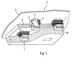
- Fig. 1 are several holding devices according to the invention 1 shown installed in a ceiling 2 of a furnace.
- the core of the holding device 1 according to the invention thereby an anchor stone 3, which is partially supported by a claw 4 is embraced.
- the claw 4 is in turn one Bracket 5 attached to a metallic furnace wall 6.
- the claw 4 is wrapped with an insulating mat 7, and the insulating mat 7 is in turn in one area Insulation 8, embedded over an insulating wool 9.
- the Insulating mat 7, the insulation 8 and the insulating wool 9 run between the metallic furnace wall 6 and a monolithic liner 10 over one, on Train designed, adhesion on the anchor stones 3 and the fasteners 4, 5 stable on the metallic Furnace wall 6 is attached.
- the ceiling installation shown in Fig. 1 can be as follows receive:
- the anchor block 3 is made to size on hydraulic high-pressure presses manufactured, the concrete design the same with reference to Fig.en 5a to 7b described in detail is.
- each fastener is still a spring plate 11 made of spring steel, the Meaning described in detail with reference to FIG. 8 is manufactured and selected a commercially available screw 12.
- the metallic bracket 5 is attached to the metallic one Furnace wall 6 welded to form a weld 13, see Fig. 2b.
- Holding devices 21 also for installation a monolithic liner 30 in a sidewall 22 use as shown in Fig. 3.
- There is an anchor stone 23 the anchorage of the monolithic lining 30 serves, via a claw 24 and a bracket 25 on one metallic furnace wall 26 attached.
- Each claw 24 is from an insulating mat 27 encased and partially in one Insulation 28, embedded over an insulating wool 29, so that the insulating materials 27, 28, 29 between the monolithic Lining 30 and the metallic furnace wall 26 for Formation of a refractory furnace wall installation are arranged.
- FIG. 3 can also be installed analogously the ceiling installation according to Fig. 1 using a spring plate 31 and a screw 32 per fastener and Production of a weld 33 between each bracket 25 and create the metallic furnace wall 26, as the Fig.en 4a up to 4d.
- FIGS. 5a to 7b show three possible configurations by way of example of anchor stones 40, 50, 60 with different Length increments for different wall thicknesses for use in holding devices according to the invention in the refractory lining represented by industrial furnaces.
- each anchor stone 40, 50, 60 has a head area with a Recess 41, 51, 61 and two shoulders 42, 52, 62 as well a tapering towards the head area Fuselage with circumferential, offset grooves 43, 43 ', 53, 53 ', 63 and grooves 44, 54, 64, 64' is formed.
- Each recess 41, 51, 61 serves to receive one end a corresponding fastener screw connection.
- the shoulders 42, 52, 62 each allow a claw corresponding anchor stone 40, 50, 60 in its head area can be gripped on both sides.
- the grooves 43, 43 ', 53, 53', 63 and grooves 44, 54, 64, 64 'and the taper of the Anchor stones 40, 50, 60 are used for stable anchoring monolithic lining.
- Fig. 8 shows a fastener for use in a Holding device according to the invention, the claw 70, a Bracket 71, a spring plate 72, a hex nut 73, one Includes hexagon screw 74 and two O-rings 75, 75 '.
- an anchor stone experiences at the Installation in the claw 70 flexible storage, i.e. he is freely movably and stably supported in the fastener, so that, for example, when uncontrolled tensions arise due to possibly anisotropic thermal expansion Wedging or tearing of the anchor stone prevented becomes.
- This effect is also supported by the two O-rings 75, 75 'in the screw connection, between the Hexagon nut 73 and the claw 70 on the one hand and the spring plate 72 and the head of the hexagon screw 74 on the other hand, which in particular the claw 70 flexible to the bracket 71 holds.
Landscapes
- Engineering & Computer Science (AREA)
- Chemical & Material Sciences (AREA)
- Ceramic Engineering (AREA)
- Mechanical Engineering (AREA)
- General Engineering & Computer Science (AREA)
- Furnace Housings, Linings, Walls, And Ceilings (AREA)
- Finishing Walls (AREA)
Applications Claiming Priority (2)
| Application Number | Priority Date | Filing Date | Title |
|---|---|---|---|
| DE29611897U DE29611897U1 (de) | 1996-07-09 | 1996-07-09 | Haltevorrichtung für monolithisch ausgekleidete Ofenwände |
| DE29611897U | 1996-07-09 |
Publications (3)
| Publication Number | Publication Date |
|---|---|
| EP0818662A2 true EP0818662A2 (fr) | 1998-01-14 |
| EP0818662A3 EP0818662A3 (fr) | 1998-01-28 |
| EP0818662B1 EP0818662B1 (fr) | 2003-05-07 |
Family
ID=8026231
Family Applications (1)
| Application Number | Title | Priority Date | Filing Date |
|---|---|---|---|
| EP97107268A Expired - Lifetime EP0818662B1 (fr) | 1996-07-09 | 1997-06-25 | Dispositif pour supporter des parois de four garnies d'un revêtement monolithique |
Country Status (3)
| Country | Link |
|---|---|
| EP (1) | EP0818662B1 (fr) |
| AT (1) | ATE239892T1 (fr) |
| DE (2) | DE29611897U1 (fr) |
Cited By (2)
| Publication number | Priority date | Publication date | Assignee | Title |
|---|---|---|---|---|
| DE202009015430U1 (de) | 2009-11-12 | 2010-01-28 | Nebgen, Peter, Dipl.-Ing. | Haltevorrichtung für einen keramischen Ankerstein |
| WO2022248411A1 (fr) * | 2021-05-27 | 2022-12-01 | Refractory Intellectual Property Gmbh & Co. Kg | Dispositif de maintien pour maintenir une pierre d'ancrage en céramique sur une paroi de four, four comprenant un tel dispositif de maintien, procédé de fixation d'un tel dispositif de maintien à une paroi de four, et pierre d'ancrage en céramique pour un tel dispositif de maintien |
Family Cites Families (8)
| Publication number | Priority date | Publication date | Assignee | Title |
|---|---|---|---|---|
| US2021610A (en) * | 1934-06-14 | 1935-11-19 | Quint George | Refractory anchor |
| US2240117A (en) * | 1939-08-17 | 1941-04-29 | A P Green Fire Brick Company | Wall anchoring means |
| US2527063A (en) * | 1944-07-03 | 1950-10-24 | Gen Refractories Co | Process of making refractory brick for use in suspended furnace roofs |
| GB1019198A (en) * | 1963-03-22 | 1966-02-02 | Morgan Refractories Ltd | Improvements in and relating to furnaces and furnace linings |
| US3295280A (en) * | 1964-04-09 | 1967-01-03 | S Obermayer Co | Furnace wall anchoring structures |
| GB1044095A (en) * | 1964-10-02 | 1966-09-28 | Detrick M H Co | Composite refractory furnace wall and component anchor brick |
| CS166981B1 (fr) * | 1973-05-07 | 1976-03-29 | ||
| AT377587B (de) * | 1981-08-26 | 1985-04-10 | Hansa Metallwerke Ag | Steuerscheibenventil, insbesondere sanitaerventil |
-
1996
- 1996-07-09 DE DE29611897U patent/DE29611897U1/de not_active Expired - Lifetime
-
1997
- 1997-06-25 DE DE59710018T patent/DE59710018D1/de not_active Expired - Lifetime
- 1997-06-25 EP EP97107268A patent/EP0818662B1/fr not_active Expired - Lifetime
- 1997-06-25 AT AT97107268T patent/ATE239892T1/de not_active IP Right Cessation
Cited By (3)
| Publication number | Priority date | Publication date | Assignee | Title |
|---|---|---|---|---|
| DE202009015430U1 (de) | 2009-11-12 | 2010-01-28 | Nebgen, Peter, Dipl.-Ing. | Haltevorrichtung für einen keramischen Ankerstein |
| EP2322889A1 (fr) | 2009-11-12 | 2011-05-18 | Peter Nebgen | Dispositif de retenue pour une pierre d'ancrage céramique et four doté d'un tel dispositif de retenue |
| WO2022248411A1 (fr) * | 2021-05-27 | 2022-12-01 | Refractory Intellectual Property Gmbh & Co. Kg | Dispositif de maintien pour maintenir une pierre d'ancrage en céramique sur une paroi de four, four comprenant un tel dispositif de maintien, procédé de fixation d'un tel dispositif de maintien à une paroi de four, et pierre d'ancrage en céramique pour un tel dispositif de maintien |
Also Published As
| Publication number | Publication date |
|---|---|
| EP0818662A3 (fr) | 1998-01-28 |
| DE29611897U1 (de) | 1996-10-31 |
| DE59710018D1 (de) | 2003-06-12 |
| EP0818662B1 (fr) | 2003-05-07 |
| ATE239892T1 (de) | 2003-05-15 |
Similar Documents
| Publication | Publication Date | Title |
|---|---|---|
| EP0593750B1 (fr) | Vis | |
| EP0440896B1 (fr) | Elément de fixation | |
| DE2557846A1 (de) | Befestigungselement fuer feuerfeste auskleidungen | |
| CH677515A5 (fr) | ||
| DE2808290A1 (de) | Verfahren und vorrichtung zur lagerung elektrischer heizelemente in einem mit keramischen fasern isolierten ofen | |
| DE2715717B2 (de) | Ankerschiene mit Schienenhalterung für ein Magnetschwebefahrzeug | |
| EP0439706A1 (fr) | Attache pour plaques de façade | |
| EP0835512B1 (fr) | Reacteur nucleaire pourvu d'une chambre collectrice pour le c ur en fusion | |
| EP0818662B1 (fr) | Dispositif pour supporter des parois de four garnies d'un revêtement monolithique | |
| DE2353179B1 (de) | Zylindrischer Kernreaktor-Druckbehaelter aus Stahlbeton | |
| DE2659316C2 (de) | Einlagekörper für Scheinfugen, insbesondere in Betonfahrbahnplatten | |
| DE3726829C2 (de) | Verfahren zur Verhinderung oder Vermeidung von Wärmeübertragung bei der Durchführung von Leitungen durch absperrende Bauteile | |
| EP0086751B1 (fr) | Ancre pouvant être soumise à la traction | |
| DE3620413C2 (fr) | ||
| EP1753916A1 (fr) | Dispositif d'ancrage, barre d'ancrage et procede de fabrication d'un dispositif d'ancrage | |
| EP1259739A1 (fr) | Clou | |
| DE10234807A1 (de) | Tragwerk zur Befestigung von Fassadenplatten an einer Zwischendecke oder dgl. | |
| DE202009015430U1 (de) | Haltevorrichtung für einen keramischen Ankerstein | |
| DE906940C (de) | Verankerung der Tragkabel einer Haengebruecke | |
| DE3307939C2 (de) | Brandschutzverkleidung | |
| DE602004004645T2 (de) | Langgestreckte Stopfenstange | |
| DE2149509A1 (de) | Werksmaessig vorgefertigte, auswechselbare platten zum auskleiden von industrieoefen | |
| DE3212462A1 (de) | Deckenabstellung | |
| DE602004001686T2 (de) | Langgestreckte Stopfenstange | |
| DE2547427C3 (de) | Schornsteinrohrelement |
Legal Events
| Date | Code | Title | Description |
|---|---|---|---|
| PUAI | Public reference made under article 153(3) epc to a published international application that has entered the european phase |
Free format text: ORIGINAL CODE: 0009012 |
|
| PUAL | Search report despatched |
Free format text: ORIGINAL CODE: 0009013 |
|
| AK | Designated contracting states |
Kind code of ref document: A2 Designated state(s): AT DE DK FR GB |
|
| AK | Designated contracting states |
Kind code of ref document: A3 Designated state(s): AT DE DK FR GB |
|
| 17P | Request for examination filed |
Effective date: 19980216 |
|
| RBV | Designated contracting states (corrected) |
Designated state(s): AT DE DK FR GB |
|
| 17Q | First examination report despatched |
Effective date: 20000411 |
|
| RAP1 | Party data changed (applicant data changed or rights of an application transferred) |
Owner name: REFRATECHNIK HOLDING GMBH & CO. KG |
|
| RAP1 | Party data changed (applicant data changed or rights of an application transferred) |
Owner name: REFRATECHNIK HOLDING GMBH |
|
| GRAH | Despatch of communication of intention to grant a patent |
Free format text: ORIGINAL CODE: EPIDOS IGRA |
|
| GRAH | Despatch of communication of intention to grant a patent |
Free format text: ORIGINAL CODE: EPIDOS IGRA |
|
| GRAA | (expected) grant |
Free format text: ORIGINAL CODE: 0009210 |
|
| AK | Designated contracting states |
Designated state(s): AT DE DK FR GB |
|
| PG25 | Lapsed in a contracting state [announced via postgrant information from national office to epo] |
Ref country code: GB Free format text: LAPSE BECAUSE OF FAILURE TO SUBMIT A TRANSLATION OF THE DESCRIPTION OR TO PAY THE FEE WITHIN THE PRESCRIBED TIME-LIMIT Effective date: 20030507 Ref country code: FR Free format text: LAPSE BECAUSE OF FAILURE TO SUBMIT A TRANSLATION OF THE DESCRIPTION OR TO PAY THE FEE WITHIN THE PRESCRIBED TIME-LIMIT Effective date: 20030507 |
|
| REG | Reference to a national code |
Ref country code: GB Ref legal event code: FG4D Free format text: NOT ENGLISH |
|
| REF | Corresponds to: |
Ref document number: 59710018 Country of ref document: DE Date of ref document: 20030612 Kind code of ref document: P |
|
| PG25 | Lapsed in a contracting state [announced via postgrant information from national office to epo] |
Ref country code: AT Free format text: LAPSE BECAUSE OF NON-PAYMENT OF DUE FEES Effective date: 20030625 |
|
| PG25 | Lapsed in a contracting state [announced via postgrant information from national office to epo] |
Ref country code: DK Free format text: LAPSE BECAUSE OF FAILURE TO SUBMIT A TRANSLATION OF THE DESCRIPTION OR TO PAY THE FEE WITHIN THE PRESCRIBED TIME-LIMIT Effective date: 20030807 |
|
| GBV | Gb: ep patent (uk) treated as always having been void in accordance with gb section 77(7)/1977 [no translation filed] |
Effective date: 20030507 |
|
| PLBE | No opposition filed within time limit |
Free format text: ORIGINAL CODE: 0009261 |
|
| STAA | Information on the status of an ep patent application or granted ep patent |
Free format text: STATUS: NO OPPOSITION FILED WITHIN TIME LIMIT |
|
| 26N | No opposition filed |
Effective date: 20040210 |
|
| EN | Fr: translation not filed | ||
| PGFP | Annual fee paid to national office [announced via postgrant information from national office to epo] |
Ref country code: DE Payment date: 20150701 Year of fee payment: 19 |
|
| REG | Reference to a national code |
Ref country code: DE Ref legal event code: R119 Ref document number: 59710018 Country of ref document: DE |
|
| PG25 | Lapsed in a contracting state [announced via postgrant information from national office to epo] |
Ref country code: DE Free format text: LAPSE BECAUSE OF NON-PAYMENT OF DUE FEES Effective date: 20170103 |