EP0818736A2 - System zur Zuweisung eines Bootstrap-Prozessors in einem symmetrischen Multiprozessorrechner mit Rückstellung von Zeitüberwachungsschaltung - Google Patents
System zur Zuweisung eines Bootstrap-Prozessors in einem symmetrischen Multiprozessorrechner mit Rückstellung von Zeitüberwachungsschaltung Download PDFInfo
- Publication number
- EP0818736A2 EP0818736A2 EP97111466A EP97111466A EP0818736A2 EP 0818736 A2 EP0818736 A2 EP 0818736A2 EP 97111466 A EP97111466 A EP 97111466A EP 97111466 A EP97111466 A EP 97111466A EP 0818736 A2 EP0818736 A2 EP 0818736A2
- Authority
- EP
- European Patent Office
- Prior art keywords
- boot strap
- processor
- working
- assignment
- working processors
- Prior art date
- Legal status (The legal status is an assumption and is not a legal conclusion. Google has not performed a legal analysis and makes no representation as to the accuracy of the status listed.)
- Withdrawn
Links
Images


Classifications
-
- G—PHYSICS
- G06—COMPUTING OR CALCULATING; COUNTING
- G06F—ELECTRIC DIGITAL DATA PROCESSING
- G06F15/00—Digital computers in general; Data processing equipment in general
- G06F15/16—Combinations of two or more digital computers each having at least an arithmetic unit, a program unit and a register, e.g. for a simultaneous processing of several programs
- G06F15/177—Initialisation or configuration control
-
- G—PHYSICS
- G06—COMPUTING OR CALCULATING; COUNTING
- G06F—ELECTRIC DIGITAL DATA PROCESSING
- G06F9/00—Arrangements for program control, e.g. control units
- G06F9/06—Arrangements for program control, e.g. control units using stored programs, i.e. using an internal store of processing equipment to receive or retain programs
- G06F9/44—Arrangements for executing specific programs
- G06F9/4401—Bootstrapping
- G06F9/4405—Initialisation of multiprocessor systems
-
- G—PHYSICS
- G06—COMPUTING OR CALCULATING; COUNTING
- G06F—ELECTRIC DIGITAL DATA PROCESSING
- G06F9/00—Arrangements for program control, e.g. control units
- G06F9/06—Arrangements for program control, e.g. control units using stored programs, i.e. using an internal store of processing equipment to receive or retain programs
- G06F9/46—Multiprogramming arrangements
- G06F9/50—Allocation of resources, e.g. of the central processing unit [CPU]
Definitions
- Multiprocessor computers implement varying levels of symmetry. Master-slave processor computer systems are very asymmetric, whereas in computers designed with higher levels of symmetry, each of the working processors are capable of performing the same functions. In symmetric computers, the working processors share buses, address the same memory and basic input/output system (BIOS) resources, and receive the same array of interrupts.
- BIOS basic input/output system
- Symmetric multiprocessor computers also tend to have a non-hierarchal bus arbitration process.
- the Intel® Pentium-Pro® Processor Bus arbitration protocol supports fair arbitration between a maximum of four working processors in the typical multiprocessor configuration.
- a unique identification i.e., agent ID of 0, 1, 2, or 3, is assigned to each working processor as part of the power-on configuration by a central agent that is also responsible for bus arbitration control.
- Bus arbitration between the working processors is then made using a round-robin algorithm, which arranges the working processors in a circular order of priority: 0, 1, 2, 3, 0, 1, 2, etc.
- the working processor with the highest priority becomes the bus owner on every arbitration event, and the working processor that owns the bus is allowed to request its use. Input/output and possibly memory subsystems may, however, have higher priority, defeating the immediate use of the bus by the working processor.
- the symmetry in some multiprocessor computers tends to break down when considering reset protocol in which the computer is bootstrapped after being powered-on or rebooted after an operating system failure.
- Pentium-Pro® multiprocessor systems fall into this class.
- the same working processor (called the boot strap processor) performs the bootstrapping operations every time the computer is powered-on.
- the bootstrapping can generally not be assigned among the other working processors even though they have access to the same computer system resources and would thus be capable of performing the role of boot strap processor.
- the asymmetry in the reset process has undesirable artifacts. It is not entirely uncommon for at least one of the working processors in a multiprocessor computer to fail. If the failed working processor is also the assigned boot strap processor then the computer as a whole is inoperable. This risk is unacceptable for expensive multiprocessor computers performing time critical functions.
- the computer's failure should be avoidable. It is common for these computers to have a system management processor that monitors environmental conditions and shut-down events. From this information, the system management processor many times can predict the failure of the working processor, to which bootstrapping is assigned. Because of the asymmetry and rigidity of the computers in prior art designs, however, bootstrap processor reassignment cannot occur.
- the invention in its broad form, resides in a boot strap assignment system in a symmetric multiprocessor computer, and a method therefor, as recited in claims 1 and 9 respectively.
- a preferred embodiment described hereinafter features a boot strap assignment method and system for a multiprocessor computer.
- the computer is symmetric at least to the extent that each of the working processors of the computer may perform the role of the boot strap processor. This role is assigned among the working processors by a central agent as part of the power-on configuration.
- An example of the central agent is a bus arbitration controller.
- the assignment system involves a system management processor which monitors the operation of the multiprocessor computer and controls a switching circuit that selectively transmits the boot strap assignment from the central agent to the working processors.
- the switching circuit comprises a plurality of switches that intercept the boot strap assignment signal transmitted from the central agent to bus request lines passing between the working processors.
- a demultiplexor is used to decode boot strap selection signals from the system management processor.
- One of the switches is then selectively closed to pass the boot strap assignment to only one of the bus request lines.
- a watch dog timer function may be further included. This timer is then reset upon finishing bootstrapping the multiprocessor computer. Should the timer time-out after measuring a predetermined amount of time, however, the system management processor assumes a bootstrap failure. Accordingly, the system management processor assigns a new working processor as the boot strap processor utilizing the inventive switch circuit.
- the invention may also be characterized as a method of assigning the bootstrapping function among multiple processors in a multiprocessor computer.
- the method includes intercepting the boot strap assignment signal from the central agent while determining which one of the multiple processors should perform the bootstrapping. The signal is then transmitted to the working processors to effect the selection.
- FIG. 1 shows the prior art bus arbitration aspects of a Pentium-Pro® multiprocessor computer having four working processors P0, P1, P2, P3.
- Each of the working processors includes four bus request pins BR0, BR1, BR2, BR3 that are associated with bus arbitration.
- the BR0 bus request pin is an input/output pin on each of the working processors and is used to signal arbitration requests for the bus during normal operation.
- the BR1, BR2, BR3 bus request pin of each working processor are input only pins, being used to monitor the arbitration requests of the respective other working processors.
- Bus request lines BREQ0#, BREQ1#, BREQ2#, BREQ3# are distributed among the four working processors P0, P1, P2, P3 in a rotating fashion.
- the BR0 pin of the first processor P0 for example is connected to the bus request line BREQ0#; the BR0 pin of the second processor P1 is connected to the BREQ1# bus request line, and so on.
- the BR1 pin of the first processor P0 is connected to the BREQ1# bus request line; the BR1 pin of the second processor P1 is connected to the BREQ2# bus request line. The remaining lines and pins are connected in this fashion.
- bus arbitration the bus owner among the working processors P0, P1, P2, P3 will arbitrate the bus via its BR0 pin.
- the bus request is passed to the BR1, BR2, BR3 pins of the other working processors via the bus request lines. In this way, each working processor P0, P1, P2, P3 can send its bus requests to the other working processors while monitoring the other processors requests.
- Bus ownership which is coordinated via the bus request lines, is rotated among the working processors based upon the agent ID.
- Each working processor maintains its agent ID, assigned as part of the power-on configuration, and an ID that indicates the current bus owner.
- every working processor P0-P3 is assigned its unique agent ID.
- a central agent 12 the bus arbitration controller, is responsible for asserting the BREQ0# bus signal during reset.
- each of the working processors P0-P3 samples its BR1, BR2, BR3 pins to determine its corresponding agent ID for arbitration.
- processor P0 would have an agent ID of 0 since none of its BR1, BR2, and BR3 pins are active, and processor P3 would have an agent ID of 3 since its BR1 pin is active. The agent ID cannot change without the re-assertion of the RESET#.
- the working processor that is assigned the agent ID of 0 recognizes that it is the boot strap processor. After the RESET# signal goes inactive, this assigned boot strap processor will automatically begin bootstrapping the computer and in time will bring the other working processors on-line. Since processor P0 must always receive the agent ID of 0, it is always the boot strap processor.
- FIG. 2 shows a modification to the bus arbitration system that enables the control of the above-described boot strap processor assignment process.
- the assignment signal on line AS from the bus arbitration system controller 12 is intercepted by switch circuit 14.
- the circuit 14 preferably uses CMOS switches to lower electrical loading and reduce delay time. This allows the timing requirements of the original specifications to be met.
- the switch circuit 14 selectively transmits the assignment signal only to one of the bus request lines BREQ0#, BREQ1#, BREQ2#, BREQ3# during the assertion of the RESET# signal. This process has the effect of controlling the assignment of the agent IDs among the working processors P0, P1, P2, and P3, thus selectively dictating the boot strap processor.
- the switch circuit 14 is controlled by a 8031 system management processor 16 through a latch 18 and demultiplexor 20.
- the system processor 16 performs a watch dog timer function in which it initiates its own reset of the working processors P0, P1, P2, P3 via OR gate 22, which also receives the system reset signal RESET#.
- the system management processor 16 is also connected to transducers, not shown, distributed around the computer to monitor environmental conditions such as temperature and line voltage. Additionally, it has non-volatile persistent storage and can access the main logic boards of the computer to interrogate the previously saved shut-down events.
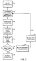
- FIG. 3 is a process diagram illustrating the boot strap assignment of the present invention utilizing the switch circuit 14 of Fig. 2. Based upon the available information such as previous, shut-down events and environmental conditions of the computer, the system management processor 16 determines which of the working processors P0, P1, P2, and P3 is functioning properly and is thus qualified to perform the bootstrapping operation in step 110.
- the selection signal from the system management processor 16 is stored in the latch 18.
- the two-bit output BSPS0, BSPS1 of the latch 18 is provided to the S0 and S1 ports respectively of a 2:4 demultiplexer 20.
- the demultiplexer 20 closes only one of the normally open CMOS switches 14 in response to receiving CRESET# signal at its enable port EN# in step 112. It therefore selects one of the bus request lines to receive the assignment signal AS from the bus arbitration controller 12.
- CRESET# is a delayed version of the system reset signal RESET# so that it is still valid on the active to inactive transition of the system reset signal RESET #, which causes the processors to sample their respective BR1-BR3 pins.
- the selection process of the switches 14 determines the agent IDs, step 114, for the working processors P0-P3 since the assignment signal as is provided on the selected one of BREQ0# through BREQ3# lines. Based upon the established agent ID assignment protocol, the working processor whose BR0 pin is active and whose BR1, BR2 and BR3 pins remain inactive assumes the agent ID of 0, and takes the role as the boot strap processor. The working processor whose BR1 pin is active assumes the agent ID of 3; the working processor whose BR2 pin is active assumes the agent ID of 2; and the working processor whose BR3 pin is active assumes the agent ID of 1.
- CRESET# Shortly after the system reset signal RESET# is inactive, CRESET# is also de-asserted. When this occurs, the demultiplexor 20 is no longer enabled causing the CMOS switches 14 to open. Thus, the bus request lines BREQ0# through BREQ3# become isolated and will not be influenced during normal operation by residual electrical loading from the added circuitry of the CMOS switches 14.
- the assigned bootstrap processor accesses the boot address space in step 116. It initializes all functions on the system, finishes diagnostics, and wakes up the remaining working processors one at a time to ensure that they are properly functioning.
- the boot strap processor also updates a table that is accessible to the operating system indicating which of working processors are operating properly.
- the system management processor 16 In parallel with the boot strapping of the computer, the system management processor 16 also initializes a watchdog timer function to begin counting-down from a predetermined time period in step 117. In the preferred embodiment, the time period is five seconds.
- the final role of the assigned bootstrap processor is to signal the system management processor to reset the watchdog timer function.
- the resetting of the watchdog timer at the end of the bootstrapping indicates to the system management processor 16 that the bootstrapping operation was successful and that operation is proceeding normally.
- the boot strap processor will never reach the end of the bootstrapping operation and signal the system management processor 16.
- the watchdog timer will time-out indicating unsuccessful bootstrapping in step 120.
- system management processor 16 When the watchdog timer times-out, the system management processor 16 initiates a second reset operation and assigns the bootstrapping function to another processor by asserting its own reset to the working processor via the OR gate 22 with appropriate control of CRESET#, step 122. An indication of this newly assigned processor is stored in latch 18, and steps 111 through 117 are repeated as illustrated by loop 200 in Fig. 3. Further, system management processor 16 identifies and labels the working processor that failed in the bootstrapping operation as inoperative. The newly assigned boot strap processor subsequently updates the table to indicate the failed processor to the operating system.
Landscapes
- Engineering & Computer Science (AREA)
- Software Systems (AREA)
- Theoretical Computer Science (AREA)
- Physics & Mathematics (AREA)
- General Engineering & Computer Science (AREA)
- General Physics & Mathematics (AREA)
- Computer Hardware Design (AREA)
- Computer Security & Cryptography (AREA)
- Debugging And Monitoring (AREA)
- Power Sources (AREA)
- Hardware Redundancy (AREA)
- Multi Processors (AREA)
Applications Claiming Priority (2)
| Application Number | Priority Date | Filing Date | Title |
|---|---|---|---|
| US678891 | 1996-07-12 | ||
| US08/678,891 US5860002A (en) | 1996-07-12 | 1996-07-12 | System for assigning boot strap processor in symmetric multiprocessor computer with watchdog reassignment |
Publications (2)
| Publication Number | Publication Date |
|---|---|
| EP0818736A2 true EP0818736A2 (de) | 1998-01-14 |
| EP0818736A3 EP0818736A3 (de) | 2005-08-24 |
Family
ID=24724723
Family Applications (1)
| Application Number | Title | Priority Date | Filing Date |
|---|---|---|---|
| EP97111466A Withdrawn EP0818736A3 (de) | 1996-07-12 | 1997-07-07 | System zur Zuweisung eines Bootstrap-Prozessors in einem symmetrischen Multiprozessorrechner mit Rückstellung von Zeitüberwachungsschaltung |
Country Status (2)
| Country | Link |
|---|---|
| US (2) | US5860002A (de) |
| EP (1) | EP0818736A3 (de) |
Cited By (1)
| Publication number | Priority date | Publication date | Assignee | Title |
|---|---|---|---|---|
| WO2005038652A1 (en) * | 2003-10-06 | 2005-04-28 | Intel Corporation | Optimization of smi handling and initialization |
Families Citing this family (43)
| Publication number | Priority date | Publication date | Assignee | Title |
|---|---|---|---|---|
| US5904733A (en) * | 1997-07-31 | 1999-05-18 | Intel Corporation | Bootstrap processor selection architecture in SMP systems |
| US6058475A (en) * | 1997-09-22 | 2000-05-02 | Ncr Corporation | Booting method for multi-processor computer |
| JP3614650B2 (ja) * | 1998-03-20 | 2005-01-26 | 富士通株式会社 | マルチプロセッサ制御方式及びこれに用いられるブート装置及びブート制御装置 |
| US6701429B1 (en) * | 1998-12-03 | 2004-03-02 | Telefonaktiebolaget Lm Ericsson(Publ) | System and method of start-up in efficient way for multi-processor systems based on returned identification information read from pre-determined memory location |
| JP2000187600A (ja) * | 1998-12-22 | 2000-07-04 | Nec Corp | ウオッチドッグタイマ方式 |
| US6665761B1 (en) | 1999-07-28 | 2003-12-16 | Unisys Corporation | Method and apparatus for routing interrupts in a clustered multiprocessor system |
| US6687818B1 (en) | 1999-07-28 | 2004-02-03 | Unisys Corporation | Method and apparatus for initiating execution of an application processor in a clustered multiprocessor system |
| US6760708B1 (en) | 1999-08-19 | 2004-07-06 | Dell Products L.P. | Method and system for migrating stored data to a build-to-order computing system |
| US6606716B1 (en) | 1999-10-06 | 2003-08-12 | Dell Usa, L.P. | Method and system for automated technical support for computers |
| IE20000602A1 (en) * | 1999-08-19 | 2001-04-18 | Dell Products Lp | Method and system for automated technical support for computers |
| US6560726B1 (en) * | 1999-08-19 | 2003-05-06 | Dell Usa, L.P. | Method and system for automated technical support for computers |
| US7996843B2 (en) * | 1999-08-25 | 2011-08-09 | Qnx Software Systems Gmbh & Co. Kg | Symmetric multi-processor system |
| US6556431B1 (en) | 1999-10-06 | 2003-04-29 | Dell Usa, L.P. | System and method for converting alternating current into direct current |
| US6317316B1 (en) | 1999-10-06 | 2001-11-13 | Dell Usa, L.P. | Method and system for integrated personal computer components |
| US6564220B1 (en) | 1999-10-06 | 2003-05-13 | Dell Usa, L.P. | System and method for monitoring support activity |
| US6563698B1 (en) | 1999-10-06 | 2003-05-13 | Dell Usa, L.P. | System and method for providing a computer system with a detachable component |
| US6539499B1 (en) | 1999-10-06 | 2003-03-25 | Dell Usa, L.P. | Graphical interface, method, and system for the provision of diagnostic and support services in a computer system |
| US6574615B1 (en) | 1999-10-06 | 2003-06-03 | Dell Usa, L.P. | System and method for monitoring support activity |
| US6598223B1 (en) | 1999-10-06 | 2003-07-22 | Dell Usa, L.P. | Method and system for installing and testing build-to-order components in a defined configuration computer system |
| US6611911B1 (en) | 1999-12-30 | 2003-08-26 | Intel Corporation | Bootstrap processor election mechanism on multiple cluster bus system |
| US6487464B1 (en) * | 2000-02-25 | 2002-11-26 | Intel Corporation | Power-on software for robust boot |
| US6584560B1 (en) * | 2000-04-19 | 2003-06-24 | Dell Usa, L.P. | Method and system for booting a multiprocessor computer |
| US7366888B2 (en) * | 2001-06-07 | 2008-04-29 | Lenovo Singapore Pte. Ltd | Booting to a recovery/maintenance environment |
| US7251723B2 (en) * | 2001-06-19 | 2007-07-31 | Intel Corporation | Fault resilient booting for multiprocessor system using appliance server management |
| US7003775B2 (en) * | 2001-08-17 | 2006-02-21 | Hewlett-Packard Development Company, L.P. | Hardware implementation of an application-level watchdog timer |
| US6996745B1 (en) | 2001-09-27 | 2006-02-07 | Sun Microsystems, Inc. | Process for shutting down a CPU in a SMP configuration |
| US20030074506A1 (en) * | 2001-10-16 | 2003-04-17 | International Business Machines Corporation | Extending processors from two-way to four-way configuration |
| US7676606B1 (en) * | 2002-04-24 | 2010-03-09 | Cisco Technology, Inc. | Method and system for monitoring and controlling status of programmable devices |
| US7065641B2 (en) * | 2002-06-13 | 2006-06-20 | Intel Corporation | Weighted processor selection apparatus and method for use in multiprocessor systems |
| US7100034B2 (en) * | 2003-05-23 | 2006-08-29 | Hewlett-Packard Development Company, L.P. | System for selecting another processor to be the boot strap processor when the default boot strap processor does not have local memory |
| US7480720B2 (en) * | 2003-06-25 | 2009-01-20 | International Business Machines Corporation | Method and system for load balancing switch modules in a server system and a computer system utilizing the same |
| US7363484B2 (en) * | 2003-09-15 | 2008-04-22 | Hewlett-Packard Development Company, L.P. | Apparatus and method for selectively mapping proper boot image to processors of heterogeneous computer systems |
| KR100568246B1 (ko) * | 2003-11-19 | 2006-04-05 | 삼성전자주식회사 | 컴퓨터 시스템 및 그 제어방법 |
| US20070067614A1 (en) * | 2005-09-20 | 2007-03-22 | Berry Robert W Jr | Booting multiple processors with a single flash ROM |
| US7366810B2 (en) * | 2005-11-16 | 2008-04-29 | Via Technologies, Inc. | Method and system for multi-processor arbitration |
| US8868424B1 (en) * | 2008-02-08 | 2014-10-21 | West Corporation | Interactive voice response data collection object framework, vertical benchmarking, and bootstrapping engine |
| US8364940B2 (en) | 2010-05-28 | 2013-01-29 | Microsoft Corporation | Automatically starting servers at low temperatures |
| TWI446161B (zh) * | 2010-12-30 | 2014-07-21 | Ibm | 處理一多處理器資訊處理系統之一故障處理器的裝置及方法 |
| US8954721B2 (en) | 2011-12-08 | 2015-02-10 | International Business Machines Corporation | Multi-chip initialization using a parallel firmware boot process |
| EP3324288B1 (de) * | 2016-11-21 | 2021-09-08 | VIA Technologies, Inc. | Mehrkernmikroprozessor, der einen seiner prozessorkerne dynamisch als bootstrap-prozessor bestimmt |
| US11842202B2 (en) * | 2019-10-25 | 2023-12-12 | Intel Corporation | Apparatus and method for dynamic selection of an optimal processor core for power-up and/or sleep modes |
| CN113064747B (zh) * | 2021-03-26 | 2022-10-28 | 山东英信计算机技术有限公司 | 一种服务器启动过程中的故障定位方法、系统及装置 |
| US12190120B2 (en) * | 2022-06-21 | 2025-01-07 | Stmicroelectronics Application Gmbh | Processing system, related integrated circuit, device and method |
Family Cites Families (8)
| Publication number | Priority date | Publication date | Assignee | Title |
|---|---|---|---|---|
| JPH06103481B2 (ja) * | 1985-11-15 | 1994-12-14 | 株式会社日立製作所 | プログラムロ−デイング方式 |
| GB8823509D0 (en) * | 1988-10-06 | 1988-11-16 | Int Computers Ltd | Bootstrap mechanism for data processing system |
| DE59005468D1 (de) * | 1989-03-21 | 1994-05-26 | Siemens Nixdorf Inf Syst | Multiprozessorsystem. |
| US5497497A (en) * | 1989-11-03 | 1996-03-05 | Compaq Computer Corp. | Method and apparatus for resetting multiple processors using a common ROM |
| JP3461825B2 (ja) * | 1991-06-26 | 2003-10-27 | 三星電子株式会社 | マルチプロセッサ分散型初期化および自己テストシステム |
| US5491788A (en) * | 1993-09-10 | 1996-02-13 | Compaq Computer Corp. | Method of booting a multiprocessor computer where execution is transferring from a first processor to a second processor based on the first processor having had a critical error |
| US5627962A (en) * | 1994-12-30 | 1997-05-06 | Compaq Computer Corporation | Circuit for reassigning the power-on processor in a multiprocessing system |
| US5768585A (en) * | 1995-11-21 | 1998-06-16 | Intel Corporation | System and method for synchronizing multiple processors during power-on self testing |
-
1996
- 1996-07-12 US US08/678,891 patent/US5860002A/en not_active Expired - Lifetime
-
1997
- 1997-07-07 EP EP97111466A patent/EP0818736A3/de not_active Withdrawn
-
1998
- 1998-10-23 US US09/178,184 patent/US6009521A/en not_active Expired - Lifetime
Cited By (4)
| Publication number | Priority date | Publication date | Assignee | Title |
|---|---|---|---|---|
| WO2005038652A1 (en) * | 2003-10-06 | 2005-04-28 | Intel Corporation | Optimization of smi handling and initialization |
| GB2422230A (en) * | 2003-10-06 | 2006-07-19 | Intel Corp | Optimization Of SMI Handling And Initialization |
| GB2422230B (en) * | 2003-10-06 | 2007-07-11 | Intel Corp | Optimization Of SMI Handling And Initialization |
| US7493435B2 (en) | 2003-10-06 | 2009-02-17 | Intel Corporation | Optimization of SMI handling and initialization |
Also Published As
| Publication number | Publication date |
|---|---|
| US6009521A (en) | 1999-12-28 |
| US5860002A (en) | 1999-01-12 |
| EP0818736A3 (de) | 2005-08-24 |
Similar Documents
| Publication | Publication Date | Title |
|---|---|---|
| US5860002A (en) | System for assigning boot strap processor in symmetric multiprocessor computer with watchdog reassignment | |
| JP3962394B2 (ja) | ホットプラグ可能な問題のあるコンポーネントの動的検出および問題のあるコンポーネントからのシステムリソースの再割り当て | |
| US6112320A (en) | Computer watchdog timer | |
| JP3976275B2 (ja) | Smpにおけるサーバノードの非介入動的ホットプラグおよびホット除去 | |
| JP3706542B2 (ja) | 処理コアの使用を動的に更新する方法および装置 | |
| US5125081A (en) | Inter-configuration changing controller based upon the connection and configuration information among plurality of clusters and the global storage | |
| US5828821A (en) | Checkpoint restart method and apparatus utilizing multiple log memories | |
| US7584345B2 (en) | System for using FPGA technology with a microprocessor for reconfigurable, instruction level hardware acceleration | |
| US8082470B2 (en) | Share resources and increase reliability in a server environment | |
| CA1335843C (en) | Programmable option select | |
| US6584560B1 (en) | Method and system for booting a multiprocessor computer | |
| US6295566B1 (en) | PCI add-in-card capability using PCI-to-PCI bridge power management | |
| JP2005011319A (ja) | 非対称データ処理システムリソースの非介入動的ホット追加およびホット除去 | |
| US20020133693A1 (en) | Apparatus and method for implementing fault resilient booting in a multi-processor system by using flush command to control resetting of the processors and isolating failed processors | |
| JP2007149116A (ja) | クラスタ化マルチプロセッサシステム内でアプリケーションプロセッサの実行を開始する方法および装置 | |
| US11876732B2 (en) | Method for managing the configuration of access to peripherals and their associated resources of a system on chip, and corresponding system on chip | |
| US20030145194A1 (en) | Bootstrap processor election mechanism on multiple cluster bus systems | |
| US7194614B2 (en) | Boot swap method for multiple processor computer systems | |
| US20090083467A1 (en) | Method and System for Handling Interrupts Within Computer System During Hardware Resource Migration | |
| US7251744B1 (en) | Memory check architecture and method for a multiprocessor computer system | |
| US20080040600A1 (en) | System and Method for Reducing Instability In An Information Handling System | |
| US5408647A (en) | Automatic logical CPU assignment of physical CPUs | |
| WO1994008291A9 (en) | AUTOMATIC LOGICAL CPU ASSIGNMENT OF PHYSICAL CPUs | |
| US6598105B1 (en) | Interrupt arbiter for a computing system | |
| US11966750B2 (en) | System-on-chip management controller |
Legal Events
| Date | Code | Title | Description |
|---|---|---|---|
| PUAI | Public reference made under article 153(3) epc to a published international application that has entered the european phase |
Free format text: ORIGINAL CODE: 0009012 |
|
| AK | Designated contracting states |
Kind code of ref document: A2 Designated state(s): AT BE CH DE DK ES FI FR GB GR IE IT LI LU MC NL PT SE |
|
| AX | Request for extension of the european patent |
Free format text: AL;LT;LV;RO;SI |
|
| RAP1 | Party data changed (applicant data changed or rights of an application transferred) |
Owner name: COMPAQ COMPUTER CORPORATION |
|
| RAP1 | Party data changed (applicant data changed or rights of an application transferred) |
Owner name: HEWLETT-PACKARD DEVELOPMENT COMPANY, L.P. |
|
| PUAL | Search report despatched |
Free format text: ORIGINAL CODE: 0009013 |
|
| AK | Designated contracting states |
Kind code of ref document: A3 Designated state(s): AT BE CH DE DK ES FI FR GB GR IE IT LI LU MC NL PT SE |
|
| AX | Request for extension of the european patent |
Extension state: AL LT LV RO SI |
|
| 17P | Request for examination filed |
Effective date: 20060224 |
|
| AKX | Designation fees paid |
Designated state(s): DE FR GB IT NL |
|
| GRAP | Despatch of communication of intention to grant a patent |
Free format text: ORIGINAL CODE: EPIDOSNIGR1 |
|
| STAA | Information on the status of an ep patent application or granted ep patent |
Free format text: STATUS: THE APPLICATION IS DEEMED TO BE WITHDRAWN |
|
| 18D | Application deemed to be withdrawn |
Effective date: 20090811 |