EP0819080B1 - Machine d'emballage a dispositif racleur - Google Patents
Machine d'emballage a dispositif racleur Download PDFInfo
- Publication number
- EP0819080B1 EP0819080B1 EP96908249A EP96908249A EP0819080B1 EP 0819080 B1 EP0819080 B1 EP 0819080B1 EP 96908249 A EP96908249 A EP 96908249A EP 96908249 A EP96908249 A EP 96908249A EP 0819080 B1 EP0819080 B1 EP 0819080B1
- Authority
- EP
- European Patent Office
- Prior art keywords
- bars
- stripping
- sealing jaws
- product
- packaging material
- Prior art date
- Legal status (The legal status is an assumption and is not a legal conclusion. Google has not performed a legal analysis and makes no representation as to the accuracy of the status listed.)
- Expired - Lifetime
Links
- 238000004806 packaging method and process Methods 0.000 title claims description 12
- 238000007789 sealing Methods 0.000 claims description 62
- 239000005022 packaging material Substances 0.000 claims description 41
- 230000001419 dependent effect Effects 0.000 claims 1
- 239000000047 product Substances 0.000 description 29
- 239000000463 material Substances 0.000 description 3
- 239000007788 liquid Substances 0.000 description 2
- 230000015572 biosynthetic process Effects 0.000 description 1
- 239000006227 byproduct Substances 0.000 description 1
- 238000000034 method Methods 0.000 description 1
- 238000012856 packing Methods 0.000 description 1
- 230000002093 peripheral effect Effects 0.000 description 1
- 238000009966 trimming Methods 0.000 description 1
Images


Classifications
-
- B—PERFORMING OPERATIONS; TRANSPORTING
- B65—CONVEYING; PACKING; STORING; HANDLING THIN OR FILAMENTARY MATERIAL
- B65B—MACHINES, APPARATUS OR DEVICES FOR, OR METHODS OF, PACKAGING ARTICLES OR MATERIALS; UNPACKING
- B65B51/00—Devices for, or methods of, sealing or securing package folds or closures; Devices for gathering or twisting wrappers, or necks of bags
- B65B51/10—Applying or generating heat or pressure or combinations thereof
- B65B51/26—Devices specially adapted for producing transverse or longitudinal seams in webs or tubes
- B65B51/30—Devices, e.g. jaws, for applying pressure and heat, e.g. for subdividing filled tubes
Definitions
- This invention is concerned with packaging machines of the type commonly referred to as vertical form fill and seal machines.
- a web of packaging material is drawn along a former and then passes downwards in a tubular formation; the edges are then sealed longitudinally, after which horizontal seals are made at regular intervals to form mdividual packets.
- a measured quantity of product to be packaged is dropped into each packet before a top seal is formed by sealing jaws which simultaneously form the bottom seal of the next packet.
- the sealing jaws commonly include a cutting device which separates successive packets.
- FR-A-2192006 discloses a vertical form, fill and seal packaging machine for packaging liquids
- the machine is arranged to feed a tubular packing material along a downwardly extending path and comprises opposed sealing jaws for forming horizontal seals across the tubular packaging material at regular intervals and has a product control arrangement comprising opposed parallel support rods carried by endless flexible conveyors which grip the tubular packaging material above the sealing jaws as a new seal is formed and move with the packaging material until the seal is gripped between opposed cutting jaws disposed downstream of the sealing jaws.
- the purpose of the support rods is to protect the newly formed seals from the weight of liquid above the seal whilst the seal cools.
- EP-A-0165819 discloses a vertical form fill and seal packaging machine arranged to feed a tubular packaging material along a downwardly extending path and comprising opposed sealing jaws for forming horizontal seals across the tubular packaging materials at regular intervals and a product control arrangement comprising cooperating parallel stripping bars.
- the stripping bars are mounted on the sealing jaws which are arranged to rotate continuously, and thus the stripping bars rotate at the same speed as the sealing jaws.
- the invention provides a vertical form, fill and seal packaging machine arranged to feed a tubular packaging material along a downwardly extending path and comprising opposed sealing jaws for forming horizontal seals across the tubular packaging material at regular intervals and a product control arrangement comprising cooperating parallel stripping bars, characterised in that said product control arrangement comprises a conveyor arrangement on each said side of the path which conveyor arrangements each comprise at least one conveyor mounted separately from and at the side of one sealing jaws and carrying respective said stripping bars which are moved downwards by the conveyors such that the stripping bars cooperatively sweep downwardly past and on opposite sides of the packaging material prior to engagement of the packaging material by the sealing jaws to form said seals to ensure that product being packaged drops down past the sealing jaws before the jaws act to form each seal.
- the present invention thus allows the stripping bars to be driven at a greater speed than the sealing jaws while they are performing each stripping operation.
- the present invention may be adapted to provide, in addition to the stripping bars, one or more pairs of product catching bars mounted on a pair of conveyors as described above.
- the product catching bars are brought close together by the conveyors carrying them, on opposite sides of the packaging material and in a region above the sealing jaws as they form each seal, to ensure that each quantity of product does not enter the bottom seal area before the seal is formed.
- the product catching bars may be carried by the same conveyors that carry the stripping bars, or by separate conveyors
- bar as used in this context embraces rollers which can rotate about their axes, as well as bars which are non-rotatably mounted on the corresponding conveyor or conveyors.
- This invention is particularly applicable to continuously moving packaging material and sealing jaws, the jaws being for example in a rotary form.
- the drive for the packaging material in this case being normally intermittent.
- the path of the jaws may be such that the jaws remain in contact with the packaging material through a finite distance
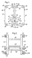
- the packaging material is only briefly engaged by the jaws while they are at about their 3 o'clock and 9 o'clock position respectively; for the purpose of illustration, Figure 1 and 2 of the attached drawings show a simple rotary jaw arrangement in that form
- Each conveyor preferably comprises two belts or chains located on opposite sides of the sealing jaws and carrying stripping bars secured at their ends to the respective belts or chains.
- the invention also includes form, fill and seal packaging machine arranged to feed a tubular packaging material along a downwardly extending path and comprising opposed sealing jaws for forming horizontal seals across the tubular packaging material at regular intervals and a product control arrangement comprising cooperating parallel stripping bars, characterised in that said product control arrangement comprises a conveyor arrangement on each said side of the path which conveyor arrangements each comprise at least one conveyor mounted separately from and at the side of the sealing jaws and carrying respective said stripping bars which are moved downwards by the conveyors on opposite sides of the packaging material prior to engagement of the packaging material by the sealing jaws to form said seals to ensure that product being packaged drops down past the sealing jaws before the jaws act to form each seal and cooperating product catching bars arranged on opposite sides of said path to prevent product dropping prematurely between jaws whereby said product control arrangement can ensure that there is no said product disposed between said jaws when said seals are formed.
- Figure 1 shows packaging material 10 moving downwards between rotary sealing members 12 and 14 which include heated sealing jaws 12A and 14A.
- the packaging material has had its longitudinal (vertical) edges sealed together, and the portion below the sealing jaws already contains product being packaged; accordingly, the lower portion 10A of the packaging material shown in Figure 1 is in an expanded condition.
- the portion of the packaging material above the sealing jaws is shown flat (i.e. unexpanded) for the sake of simple illustration, but would in practice be in an expanded condition to provide space into which the next quantity of product will be dropped immediately after the sealing jaws have come together to form the next horizontal seal.
- Each of the sealing members 12,14 is mounted on a shaft 16,18 and the opposite ends of the shafts are mounted in bearings 20.
- a drive (not shown) is connected to the right-hand end of each shaft to rotate the shafts at identical speeds so that the sealing jaws 12A,14A come together to form seals across the packaging material at regular intervals.
- a stripping device for the packaging machine comprises two pairs of belts 21,22 which pass around pulleys 24 and are located on opposite sides of the sealing jaws, as viewed in Figure 2.
- Each pair of belts carries a number of stripping bars 26 of which the ends are secured to the respective belts.
- the pulleys 24 are all mounted in cantilever fashion on shafts 28, 28a, the shafts 28A each being connected to a drive (not shown) whereby the belts are driven at the same speed (which fluctuates cyclically) and with appropriate timing with respect to the sealing jaws.
- Figure 1 shows the sealing jaws 12A,14A at positions at which they are about to engage the packaging material 10.
- Two of the stripping bars are shown in positions just below the sealing jaws, having moved downwards along parallel vertical paths in contact with the packaging material and just ahead of the sealing jaws to ensure that the product being packaged has dropped down below the corresponding sealing position.
- the stripping bars 26 are moved by the belts 22 at a speed slightly greater than that of the packaging material 10 at least during the downward-moving part of their cycle, and may then be driven more slowly during the remainder of their cycle.
- a common drive motor may be provided for the sealing jaws and belts.
- separate speed-controllable "servo" drive motors may be provided, with provision for electronic timing, these being commercially available systems; each motor in this case may be capable of modulating its speed so that the sealing intervals can be adjusted while ensuring that the sealing jaws have a peripheral speed equal to that of the packaging material while they are engaging the packaging material to form each seal, and that the cooperating stripping bars on opposite sides of the packaging material have engaged the packaging material and performed their stripping operation before the material is engaged by the sealing jaws.
- the pulleys may be arranged to form a path for each belt which converges obliquely and linearly towards the packaging material before passing around a pulley from which the belts move vertically downwards.
- the belts 21,22 may also carry product catching bars.
- product catching bars similar to the stripping bars 26 may be carried by separate pairs of belts running adjacent to the belts 21,22 (at least while moving downwards) and driven by a separate servo motor so that the speeds of these separate belts can be suitably modulated to enable the product catching bars to perform their desired operations.
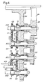
- Figure 3 shows two pairs of stripping bars 40A-D in parked positions in which they can be left if stripping is not required.
- Figure 3 (which omits certain parts for the sake of clear illustration) also shows one opposed pair of stripping bars in positions 40S and 40T in which they are about to commence their downward movement to cooperate with another in performing a stripping operation as described above with reference to the first example.
- Each of the stripping bars is mounted at its opposite ends on two chains, for example chains 42 and 44 for the stripping bar 40A shown in Figures 4 and 5.
- Each chain passes around four sprockets mounted for rotation about horizontal axes at the four corners of a rectangle.
- Two upper sprockets 45 and 46 for the chain 42 are shown, as well as two upper sprockets 48 and 50 for the chain 44.
- the corresponding opposed stripping bar 40B ( Figure 3) is similarly carried by chains of which only one chain 51 is shown passing around sprockets 102, 104 in Figure 4 Sprockets 56, 58 for the other chain are shown in Figure 4.
- a product catching roll or bar 60 Immediately behind the stripping bar 40A as it moves towards the centre line of the machine (i.e. upwards as viewed in Figure 4) is a product catching roll or bar 60. This is mounted at its opposite ends on chains 62 and 64 which run parallel to the chains 42 and 44. The chains 62 and 64 run respectively around four sprockets coaxial with the sprockets for the chains carrying the stripper bars. Sprockets 66 and 68 for the chain 62 are shown more clearly in Figure 5, which also shows upper sprockets 70 and 72 for a corresponding chain 74 supporting one end of an opposed catching roll 76 (see Figure 3).
- the chain 64 ( Figure 4) with its corresponding sprockets forms essentially a mirror image of the arrangement shown in Figure 5.
- Figure 3 shows the approaching stripping bars 40A,40B which will come together and cooperate at the position shown in dotted outlines 40S and 40T to commence the stripping action as described above.
- Figure 3 also shows the additional stripping bars 40C,40D which are at that stage moving apart, followed by product catching rolls 78 and 80 carried by the outer pairs of chains 62,64 etc.
- the sprockets are mounted on several shafts of which two shafts 80A and 80B are shown ( Figure 4) extending from one side of the machine to the other and are mounted for rotation in bearings in side frame members 82 and 84. Additional short shafts are provided for other sprockets, for example, shafts 80C and 80D as shown in Figure 5.
- the chains carrying the product catching rolls are driven by a timing belt 86 passing around a pulley 88 mounted on the shaft 80B.
- the sprocket 72 for the chain 74 is keyed to the shaft 80B so that this chain in turn drives the shaft 80D via the sprocket 70 which is keyed thereto.
- This shaft is in turn connected to the shaft 80C via gears 90 and 92 and thus drives the shaft 80C (to which the sprocket 68 is keyed) and consequently also the shaft 80A to which the sprocket 66 is keyed.
- the shafts 80A and 80B in turn drive sprockets for the other chains 64 etc which support the product catching rolls on the other side of the machine.
- the inner chains 42,44 etc carrying the stripping bars are driven by a timing belt 94 ( Figure 3) via a pulley 96 keyed to a shaft 98.
- the shaft 98 driving the adjacent sprocket (not visible in the drawings) for a stripping bar chain also drives the corresponding sprocket and chain on the other side of the machine, and the other sprockets for the stripping bar chains are driven by various gears and an additional cross shaft (not shown) in essentially the same manner as is described above with respect to the chains and sprockets for the catching rolls.
- Independent drives are provided partly so that the spacing between each stripping bar and its following catching roll can be varied during downward movement.
- the catching rolls can initially lag behind the stripping bars to create a gap sufficient for the sealing jaws to pass between them, as necessary, the catching rolls being subsequently driven at a greater speed to reduce the gaps only after the cooperating sealing jaws on the sealing members (described below) have passed beyond the 9 o'clock/3 o'clock positions sufficiently to enable the catching rolls to pass through the gap between the sealing jaws.
- separate electronically timed drives are provided for the chains and also for the sealing members to enable the distances between the successive horizontal seals on the packaging material to be varied in accordance with the desired lengths of the packets to be formed.
- the electronic drives also enable the stripping distance for each bag to be adjusted: that is to say, the distance along which the stripping bars move forwards with respect to and in close proximity to the packaging material to perform each stripping operation.
- shaft position encoders or independent sensors may be included to signal the positions of the various drives and thus enable their electronic controls to achieve the desired timing between the drives.
- This facility may include "cam” switches driven by the drives so as to make one resolution for each packet, with detectors for determining if the machine stops with any drive in a position (indicated by the corresponding "cam") in a position indicating a potential clash between two or more components of the machine (sealers, strippers and catchers).
- the drives can be initially driven by the electronic controller so as to be appropriately positioned relative to one another before the machine is brought fully into operation. During this start-up procedure the precise positions of the drives can be signalled to the electronic controller by detectors sensing the leading or trailing edge of each "cam” as it moves past the respective detector.
- FIG 4 shows two shafts 110 and 112 which carry respective rotary sealing members 114 and 116 and are mounted at their opposite ends for rotation in bearings in the side frames 82 and 84.
- Each of the sealing members has opposed (180° spaced) sealing jaws of which jaws 114A and 116B are shown in positions in which they are cooperating to form a seal in the packaging material (not shown).
- the sealing member 114 is driven by a trimming belt 117, and the sealing member 116 is driven in the opposite direction and at the same speed via gears 117A and 117B.
- Figure 3 shows one end bearing 118 for the shaft 110, and an end bearing 120 for the shaft 112.
- a spring 122 (or set of springs) is provided to load the shaft 112 towards the shaft 110 so that an adjustable contact force between the sealing members is achieved during each sealing operation.
- the spring force is adjustable by means of a bolt 124.
- Each of the sealing bars is electrically heated. Electrical power is applied to them for that purpose via fixed members 126 and 128 engaging slip rings (not shown) on the shafts.
- Figure 3 shows a chain tensioning member 130 which carries adjacent pairs of lower sprockets and is movable downwards to tension all four chains on one side of the machine.
- a similar arrangement would be provided for tensioning the chains on the other side of the machine.
- other ways of the tensioning the chains may alternatively be used to allow greater independence in the tensioning of each chain.
Landscapes
- Engineering & Computer Science (AREA)
- Mechanical Engineering (AREA)
- Package Closures (AREA)
- Containers And Plastic Fillers For Packaging (AREA)
Claims (11)
- Machine d'emballage formeuse-remplisseuse-scelleuse verticale agencée pour alimenter un matériau d'emballage tubulaire (10) le long d'une trajectoire s'étendant vers le bas et comprenant des mâchoires de scellement opposées (12A, 14A ; 114, 116) pour former des scellements horizontaux à travers le matériau d'emballage tubulaire à intervalles réguliers et un agencement de contrôle des produits comprenant des barres racleuses parallèles coopérantes (26 ; 40A, 40B, 40C, 40D), caractérisée en ce que ledit agencement de contrôle des produits comprend un agencement de convoyeur sur chacun desdits côtés de la trajectoire, lesquels agencements de convoyeur comprennent chacun au moins un convoyeur (21, 22 ; 42, 44, 51) monté séparément depuis et au niveau du côté de l'une des mâchoires de scellement et portant lesdites barres racleuses respectives qui sont déplacées vers le bas par les convoyeurs de telle sorte que les barres racleuses balaient de manière coopérative vers le bas en passant devant et sur les côtés opposés du matériau d'emballage avant la mise en prise du matériau d'emballage par les mâchoires de scellement pour former lesdits scellements, afin de garantir que le produit emballé tombe en passant devant les mâchoires de scellement avant que les mâchoires n'agissent pour former chaque scellement.
- Machine selon la revendication 1, dans laquelle chaque agencement de convoyeur comprend deux convoyeurs (21, 22 ; 42, 44, 51) agencés pour supporter les extrémités opposées des barres racleuses respectives.
- Machine selon la revendication 2, dans laquelle les convoyeurs sont des dispositifs souples sans fin qui se déplacent le long de trajectoires fermées autour d'organes de support (24 ; 45, 46, 48, 50, 56, 58, 102, 104).
- Machine selon la revendication 3, dans laquelle les convoyeurs comprennent des chaínes.
- Machine selon l'une quelconque des revendications précédentes, dans laquelle chaque agencement de convoyeur porte deux barres racleuses ou plus.
- Machine selon l'une quelconque des revendications précédentes, dans laquelle les mâchoires de scellement (12A, 14A ; 114, 116) sont montées pour tourner autour d'axes horizontaux, et dans laquelle la trajectoire de chaque convoyeur s'étend autour de l'axe de l'une des mâchoires de scellement.
- Machine selon l'une quelconque des revendications précédentes, dans laquelle ledit agencement de contrôle des produits comprend des barres de réception des produits coopérantes (60, 76, 78, 80) agencées pour coopérer afin d'empêcher la chute prématurée des produits entre lesdites mâchoires.
- Machine selon la revendication 7, lorsqu'elle dépend de la revendication 3, dans laquelle chacun desdits organes de support est fixé à ou peut tourner autour d'un arbre respectif (80A, 80B, 80C, 80D), lesquels arbres portent aussi un second organe de support respectif (66, 68, 70, 72) pour un convoyeur souple sans fin supplémentaire (62, 64, 74), lesdits convoyeurs supplémentaires portant lesdites barres de réception des produits.
- Machine selon la revendication 7, 8 ou 9, dans laquelle les barres racleuses, les barres de réception des produits et les mâchoires de scellement sont entraínées respectivement par trois moteurs indépendant et comprenant des commandes par lesquelles les moteurs sont commandés électroniquement les uns par rapport aux autres.
- Machine d'emballage selon la revendication 9, dans laquelle lesdites commandes pour les moteurs entraínant les barres racleuses et de réception sont telles qu'elles permettent aux barres racleuses et de réception des produits d'être stationnées dans des positions à distance du matériau d'emballage lorsque le raclage et la réception ne sont pas nécessaires.
- Machine selon l'une quelconque des revendications précédentes, dans laquelle chacun desdits convoyeurs est agencé pour déplacer les barres respectives le long de trajectoires s'étendant vers le bas entre les mâchoires de scellement et vers le haut sur l'extérieur des mâchoires de scellement respectives.
Applications Claiming Priority (5)
| Application Number | Priority Date | Filing Date | Title |
|---|---|---|---|
| GB9506876 | 1995-04-01 | ||
| GBGB9506876.3A GB9506876D0 (en) | 1995-04-03 | 1995-04-03 | Packaging machine |
| GBGB9605426.7A GB9605426D0 (en) | 1996-03-15 | 1996-03-15 | Packaging machine |
| GB9605426 | 1996-03-15 | ||
| PCT/GB1996/000770 WO1996032328A1 (fr) | 1995-04-01 | 1996-03-29 | Machine d'emballage a dispositif racleur |
Publications (2)
| Publication Number | Publication Date |
|---|---|
| EP0819080A1 EP0819080A1 (fr) | 1998-01-21 |
| EP0819080B1 true EP0819080B1 (fr) | 2002-01-30 |
Family
ID=26306804
Family Applications (1)
| Application Number | Title | Priority Date | Filing Date |
|---|---|---|---|
| EP96908249A Expired - Lifetime EP0819080B1 (fr) | 1995-04-01 | 1996-03-29 | Machine d'emballage a dispositif racleur |
Country Status (6)
| Country | Link |
|---|---|
| US (1) | US6006503A (fr) |
| EP (1) | EP0819080B1 (fr) |
| JP (1) | JPH11504594A (fr) |
| AU (1) | AU712551B2 (fr) |
| DE (1) | DE69618941T2 (fr) |
| WO (1) | WO1996032328A1 (fr) |
Families Citing this family (7)
| Publication number | Priority date | Publication date | Assignee | Title |
|---|---|---|---|---|
| US6581360B1 (en) * | 1997-03-21 | 2003-06-24 | Molins Plc | Packaging machinery |
| DE19719338C1 (de) * | 1997-05-07 | 1998-08-06 | Rovema Gmbh | Quersiegelvorrichtung für eine Schlauchbeutelmaschine |
| US6876896B1 (en) | 1999-04-26 | 2005-04-05 | Ab Tetrapak | Variable motion system and method |
| DE60213545T2 (de) | 2001-12-12 | 2007-08-09 | Tna Australia Pty Ltd., Lidcombe | Rotierende Siegel- und Abstreifeinheit für eine Verpackungsmaschine |
| US6928794B2 (en) * | 2003-08-01 | 2005-08-16 | 3M Innovative Properties Company | Method and apparatus for making a continuous series of filled pouches |
| CA2736010C (fr) * | 2007-12-19 | 2014-08-19 | Altentech Power Inc. | Sechoir pour produits combustibles |
| CN109455363A (zh) * | 2018-12-28 | 2019-03-12 | 浙江旭翔机械科技有限公司 | 用于横封夹爪机构的主动力系统 |
Family Cites Families (16)
| Publication number | Priority date | Publication date | Assignee | Title |
|---|---|---|---|---|
| US2915866A (en) * | 1958-05-12 | 1959-12-08 | Lynch Corp | Product settling means for draw type wrapping machine |
| US2956383A (en) * | 1959-05-19 | 1960-10-18 | Hayssen Mfg Company | Product settling attachments for packaging machines |
| US3070931A (en) * | 1961-01-10 | 1963-01-01 | Gen Packaging Equip Co | Packaging machine |
| US3262244A (en) * | 1962-10-10 | 1966-07-26 | Woodman Company Inc | Particle stopper apparatus for form and fill machine |
| US3668815A (en) * | 1970-03-12 | 1972-06-13 | Woodman Co | Vibrating clamp product settler |
| IT954476B (it) * | 1972-04-24 | 1973-08-30 | Dominici Antonio Flli | Procedimento e dispositivo per produrre contenitori d imballaggio riempiti e sigillati |
| US4663917A (en) * | 1984-06-20 | 1987-05-12 | Taylor Alfred A | Packaging apparatus |
| US4757668A (en) * | 1986-01-27 | 1988-07-19 | Ilapak Research & Development S.A. | Method and apparatus for form-fill-seal packaging of articles |
| DE3732033A1 (de) * | 1987-09-23 | 1989-04-13 | Rovema Gmbh | Siegelvorrichtung |
| DE3837709A1 (de) * | 1988-11-07 | 1990-05-10 | Rovema Gmbh | Schlauchbeutelmaschine |
| JP2540117B2 (ja) * | 1990-07-31 | 1996-10-02 | 雅夫 福田 | 包装機 |
| US5279098A (en) * | 1990-07-31 | 1994-01-18 | Ishida Scales Mfg. Co., Ltd. | Apparatus for and method of transverse sealing for a form-fill-seal packaging machine |
| AU649286B2 (en) * | 1990-11-30 | 1994-05-19 | Unilever Plc | Collating apparatus |
| DE9016520U1 (de) * | 1990-12-05 | 1991-02-21 | Rovema - Verpackungsmaschinen Gmbh, 35463 Fernwald | Stripper |
| US5412927A (en) * | 1993-11-03 | 1995-05-09 | Kawashimaseisakusyo Co., Ltd. | Longitudinal bag-making, filling and packaging machine |
| DE4412577A1 (de) * | 1994-04-13 | 1995-10-19 | Rovema Gmbh | Quersiegel-Vorrichtung für eine Schlauchbeutel-Verpackungsmaschine |
-
1996
- 1996-03-29 WO PCT/GB1996/000770 patent/WO1996032328A1/fr not_active Ceased
- 1996-03-29 DE DE69618941T patent/DE69618941T2/de not_active Expired - Fee Related
- 1996-03-29 US US08/930,541 patent/US6006503A/en not_active Expired - Fee Related
- 1996-03-29 EP EP96908249A patent/EP0819080B1/fr not_active Expired - Lifetime
- 1996-03-29 JP JP8530796A patent/JPH11504594A/ja active Pending
- 1996-03-29 AU AU51567/96A patent/AU712551B2/en not_active Ceased
Also Published As
| Publication number | Publication date |
|---|---|
| AU712551B2 (en) | 1999-11-11 |
| EP0819080A1 (fr) | 1998-01-21 |
| JPH11504594A (ja) | 1999-04-27 |
| AU5156796A (en) | 1996-10-30 |
| WO1996032328A1 (fr) | 1996-10-17 |
| DE69618941T2 (de) | 2002-11-14 |
| US6006503A (en) | 1999-12-28 |
| DE69618941D1 (de) | 2002-03-14 |
Similar Documents
| Publication | Publication Date | Title |
|---|---|---|
| EP0665796B1 (fr) | Faconneur ajustable de pourtour | |
| EP0680880B1 (fr) | Dispositif pour sceller des récipients par l'application d'une feuille de couverture | |
| EP1008523B1 (fr) | Procédé d'emballage pour une bande de sacs reliés | |
| EP1382532B1 (fr) | Dispositif de séparation en groupes de produits alimentés en continu | |
| CA1285204C (fr) | Dispositif et methode pour debiter de la pellicule d'emballage | |
| US6854242B2 (en) | Modular shrink-wrap machine | |
| WO1990005087A1 (fr) | Machines et procedes permettant de doubler la capacite de machines a empaqueter | |
| US6581360B1 (en) | Packaging machinery | |
| US5537806A (en) | Bag sealing apparatus and related method for sealing bags | |
| EP0819080B1 (fr) | Machine d'emballage a dispositif racleur | |
| EP0640526A1 (fr) | Procédé et dispositif pour manipuler un courant de produits | |
| US3147168A (en) | Bag making machine and method | |
| SK30194A3 (en) | Synchronizing device, especially for manufacturing systems and packing of food products | |
| GB1487263A (en) | Packaging apparatus | |
| CA1333180C (fr) | Methode et dispositif pour l'empilage d'articles | |
| GB2328425A (en) | Vertical form fill and seal packaging machines with optional use of stripping bars | |
| US4905446A (en) | Apparatus for wrapping articles | |
| US5123522A (en) | Sealing head bridging conveyor | |
| JP3405424B2 (ja) | 真空包装装置 | |
| JPH0534208B2 (fr) | ||
| CA1059476A (fr) | Applicateur d'un ruban de scellement sur du carton | |
| JP3464327B2 (ja) | 包装機のシール装置 | |
| EP1740461A1 (fr) | Machine a emballer sous sachets verticale | |
| IT9067648A1 (it) | Macchina confezionatrice, particolarmente per la formazione di involucri del tipo flow-pack e simili, e relativo procedimento di azionamento | |
| IT9003778A1 (it) | Gruppo di taglio ed alimentazione di film applicabile su macchine condizionatrici di prodotti. |
Legal Events
| Date | Code | Title | Description |
|---|---|---|---|
| PUAI | Public reference made under article 153(3) epc to a published international application that has entered the european phase |
Free format text: ORIGINAL CODE: 0009012 |
|
| 17P | Request for examination filed |
Effective date: 19971030 |
|
| AK | Designated contracting states |
Kind code of ref document: A1 Designated state(s): DE DK ES FR GR IE IT NL |
|
| 17Q | First examination report despatched |
Effective date: 19991213 |
|
| GRAG | Despatch of communication of intention to grant |
Free format text: ORIGINAL CODE: EPIDOS AGRA |
|
| GRAG | Despatch of communication of intention to grant |
Free format text: ORIGINAL CODE: EPIDOS AGRA |
|
| GRAH | Despatch of communication of intention to grant a patent |
Free format text: ORIGINAL CODE: EPIDOS IGRA |
|
| GRAH | Despatch of communication of intention to grant a patent |
Free format text: ORIGINAL CODE: EPIDOS IGRA |
|
| RBV | Designated contracting states (corrected) |
Designated state(s): DE DK ES FR GR IE IT NL |
|
| GRAA | (expected) grant |
Free format text: ORIGINAL CODE: 0009210 |
|
| AK | Designated contracting states |
Kind code of ref document: B1 Designated state(s): DE DK ES FR GR IE IT NL |
|
| PG25 | Lapsed in a contracting state [announced via postgrant information from national office to epo] |
Ref country code: GR Free format text: LAPSE BECAUSE OF FAILURE TO SUBMIT A TRANSLATION OF THE DESCRIPTION OR TO PAY THE FEE WITHIN THE PRESCRIBED TIME-LIMIT Effective date: 20020130 |
|
| REF | Corresponds to: |
Ref document number: 69618941 Country of ref document: DE Date of ref document: 20020314 |
|
| REG | Reference to a national code |
Ref country code: IE Ref legal event code: FG4D |
|
| PG25 | Lapsed in a contracting state [announced via postgrant information from national office to epo] |
Ref country code: IE Free format text: LAPSE BECAUSE OF NON-PAYMENT OF DUE FEES Effective date: 20020329 |
|
| PG25 | Lapsed in a contracting state [announced via postgrant information from national office to epo] |
Ref country code: DK Free format text: LAPSE BECAUSE OF FAILURE TO SUBMIT A TRANSLATION OF THE DESCRIPTION OR TO PAY THE FEE WITHIN THE PRESCRIBED TIME-LIMIT Effective date: 20020430 |
|
| PG25 | Lapsed in a contracting state [announced via postgrant information from national office to epo] |
Ref country code: ES Free format text: LAPSE BECAUSE OF FAILURE TO SUBMIT A TRANSLATION OF THE DESCRIPTION OR TO PAY THE FEE WITHIN THE PRESCRIBED TIME-LIMIT Effective date: 20020730 |
|
| PLBE | No opposition filed within time limit |
Free format text: ORIGINAL CODE: 0009261 |
|
| STAA | Information on the status of an ep patent application or granted ep patent |
Free format text: STATUS: NO OPPOSITION FILED WITHIN TIME LIMIT |
|
| REG | Reference to a national code |
Ref country code: IE Ref legal event code: MM4A |
|
| 26N | No opposition filed | ||
| PGFP | Annual fee paid to national office [announced via postgrant information from national office to epo] |
Ref country code: NL Payment date: 20030131 Year of fee payment: 8 |
|
| PGFP | Annual fee paid to national office [announced via postgrant information from national office to epo] |
Ref country code: DE Payment date: 20030221 Year of fee payment: 8 |
|
| PGFP | Annual fee paid to national office [announced via postgrant information from national office to epo] |
Ref country code: FR Payment date: 20030313 Year of fee payment: 8 |
|
| PG25 | Lapsed in a contracting state [announced via postgrant information from national office to epo] |
Ref country code: NL Free format text: LAPSE BECAUSE OF NON-PAYMENT OF DUE FEES Effective date: 20041001 Ref country code: DE Free format text: LAPSE BECAUSE OF NON-PAYMENT OF DUE FEES Effective date: 20041001 |
|
| PG25 | Lapsed in a contracting state [announced via postgrant information from national office to epo] |
Ref country code: FR Free format text: LAPSE BECAUSE OF NON-PAYMENT OF DUE FEES Effective date: 20041130 |
|
| NLV4 | Nl: lapsed or anulled due to non-payment of the annual fee |
Effective date: 20041001 |
|
| REG | Reference to a national code |
Ref country code: FR Ref legal event code: ST |
|
| PG25 | Lapsed in a contracting state [announced via postgrant information from national office to epo] |
Ref country code: IT Free format text: LAPSE BECAUSE OF NON-PAYMENT OF DUE FEES;WARNING: LAPSES OF ITALIAN PATENTS WITH EFFECTIVE DATE BEFORE 2007 MAY HAVE OCCURRED AT ANY TIME BEFORE 2007. THE CORRECT EFFECTIVE DATE MAY BE DIFFERENT FROM THE ONE RECORDED. Effective date: 20050329 |