EP0819100B1 - Filterkartusche für wasser - Google Patents
Filterkartusche für wasser Download PDFInfo
- Publication number
- EP0819100B1 EP0819100B1 EP96908952A EP96908952A EP0819100B1 EP 0819100 B1 EP0819100 B1 EP 0819100B1 EP 96908952 A EP96908952 A EP 96908952A EP 96908952 A EP96908952 A EP 96908952A EP 0819100 B1 EP0819100 B1 EP 0819100B1
- Authority
- EP
- European Patent Office
- Prior art keywords
- water
- cover member
- vessel
- mass
- filtration
- Prior art date
- Legal status (The legal status is an assumption and is not a legal conclusion. Google has not performed a legal analysis and makes no representation as to the accuracy of the status listed.)
- Expired - Lifetime
Links
Images

Classifications
-
- C—CHEMISTRY; METALLURGY
- C02—TREATMENT OF WATER, WASTE WATER, SEWAGE, OR SLUDGE
- C02F—TREATMENT OF WATER, WASTE WATER, SEWAGE, OR SLUDGE
- C02F1/00—Treatment of water, waste water, or sewage
- C02F1/001—Processes for the treatment of water whereby the filtration technique is of importance
- C02F1/003—Processes for the treatment of water whereby the filtration technique is of importance using household-type filters for producing potable water, e.g. pitchers, bottles, faucet mounted devices
-
- C—CHEMISTRY; METALLURGY
- C02—TREATMENT OF WATER, WASTE WATER, SEWAGE, OR SLUDGE
- C02F—TREATMENT OF WATER, WASTE WATER, SEWAGE, OR SLUDGE
- C02F1/00—Treatment of water, waste water, or sewage
- C02F1/28—Treatment of water, waste water, or sewage by sorption
- C02F1/283—Treatment of water, waste water, or sewage by sorption using coal, charred products, or inorganic mixtures containing them
-
- C—CHEMISTRY; METALLURGY
- C02—TREATMENT OF WATER, WASTE WATER, SEWAGE, OR SLUDGE
- C02F—TREATMENT OF WATER, WASTE WATER, SEWAGE, OR SLUDGE
- C02F2201/00—Apparatus for treatment of water, waste water or sewage
- C02F2201/002—Construction details of the apparatus
- C02F2201/006—Cartridges
-
- C—CHEMISTRY; METALLURGY
- C02—TREATMENT OF WATER, WASTE WATER, SEWAGE, OR SLUDGE
- C02F—TREATMENT OF WATER, WASTE WATER, SEWAGE, OR SLUDGE
- C02F2307/00—Location of water treatment or water treatment device
- C02F2307/04—Location of water treatment or water treatment device as part of a pitcher or jug
Definitions
- the present invention relates to a filtration cartridge to be used with a hand-held water filtration system, the filtration cartridge being adapted to permit water to flow therethrough, and containing a granular purifying agent which is insoluble in water.
- Various hand-held devices which utilize a granular purifying agent, such as activated charcoal and/or an ion exchange material for the purification of water.
- a granular purifying agent such as activated charcoal and/or an ion exchange material for the purification of water. Examples of such devices are: United States Patent No. 4,306,971 (Hansch); United States Patent No. 4,895,648 (Hanhunt); United States Patent No. 4,969,996 (Hanhunt); and, United States Patent No. 5,049,272 (Nieweg).
- these devices comprise a large funnel-shaped member to hold and channel the water to be purified, a removable filtration cartridge placed in the flow channel of the funnel-shaped member, and a collection beaker for the purified water.
- the filtration cartridge is ordinarily constructed to allow the water to flow therethrough, and contains the aforementioned granular purifying agent and/or ion exchange material.
- These filtration cartridges are typically constructed from inexpensive plastics materials and are designed to be discarded after the granular purifying agent loses its effectiveness, typically after about a month of normal household usages (i.e., after about 100 litres of water have been filtered).
- the rate of flow of water through the filter cartridge is critical for effective water purification. It is necessary to contain the water within the filtration cartridge for a sufficient time to allow for ion exchange and filtration to occur, yet if the flow rate through the cartridge is too slow, then an insufficient volume of water will be purified, in a time frame which is satisfactory to the user of the filtration system.
- Certain known filtration cartridges such as the subject of United States Patent No. 4,895,648 (Hansch)[equivalent to EP-A-0340382] and published UK Patent Application No.
- GB-A-2 197 647 (Clarke et al.), rely upon an array of water flow openings which are sufficiently small to trap the granular purifying material within the cartridge, while allowing water to pass therethrough.
- the size of the water flow openings is necessarily very small in order to trap the granular purifying agent within the cartridge; this sizing results in significant time lag for overall water filtration, since only a small volume of water can pass through the filtration cartridge openings at a given time.
- particles of the granular purifying agent to become trapped in the water flow openings, blocking them and further reducing flow rates. Further problems develop in relation to the venting of air out of the collection beaker through the filter cartridge.
- top and bottom secondary filters must be sized differently in order to fit the different top and bottom end dimensions of the filtration cartridge. More particularly, the top secondary filter is typically conical, to correspond to the general shape of the cartridge cap, which cap has been so configured to achieve adequate air ventilation.
- each of the top and bottom secondary filters must be separately manufactured using molds or dies of differing sizes and shapes. Further, it is necessary to use some form of fastening means to secure the secondary filters, most notably the top secondary filter, to the top cap of the filtration cartridge. Plastic welding is sometimes used for this purpose, as disclosed in U.S. Patent No. 5,049,272 (Nieweg). This step further complicates assembly and increases manufacturing costs.
- top and bottom secondary filters constructed of light, fluffy, loosely packed fibrous matter comprising commingled, con-woven fibres of significant length relative to their diameter has been proposed in published PCT Application Ser. No. WO-A-89/00977.
- the design of this cartridge does not have the conventional conical cap design mentioned above, which design has becom an industry standard, and no means are proposed in this reference to hold the top secondary filter within the cap to facillitate assembly as aforesaid.
- an improved water filter cartridge of the type having a substantially frustoconical vessel member defining a vertical axis, said vessel member having a screen-like end wall portion at the lower end thereof, which end wall portion permits water to flow therethrough and a hollow substantially frustoconical cover member attached to said vessel member and coaxial with the vertical axis thereof, said cover member defining an annular rim portion and a first slanted portion extending upwardly and inwardly from said rim portion, and a substantially flat-topped second portion, said first portion having a multiplicity of vertically oriented water entry flow slots arrayed therearound for use in a water filtration device.
- the improvement comprises having a non-planar compressible first mass of filtration material frictionally retained within the cover member, a non-planar compressible second mass of filtration material positioned within the vessel member in juxtaposed relation to said end-wall portion, with the first and second non-planar masses of filtration material each being constructed from a multiplicity of fine flexible fibres of a substance which is insoluble in water.
- a granular purifying agent, which is insoluble in water, is contained within the vessel member, and is layered upon the second mass of filtration material.
- a split support ring having a series of upwardly, radially inwardly slanted projections is being positioned within the cover member, in supported relation upon the rim portion of the cover member. The non-planar compressible first mass of filtration material is held in compressed relation within the cover member by the split support ring.
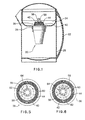
- FIG. 1 of the drawings appended hereto is a perspective view of the water filtration cartridge according to the present invention in place in a hand-held water filtration system, which system is shown in section.
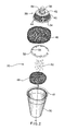
- Figure 2 of the drawings is an exploded perspective view of the water filtration cartridge of Figure 1 .
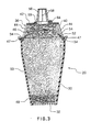
- Figure 3 of the drawings is a vertical mid-line section of the water filtration cartridge of Figure 1 when the granular purifying agent is wet;
- Figure 4 of the drawings is a view similar to Figure 3 when the granular purifying agent is dry.
- Figure 5 of the drawings is a top plan view of the water filtration cartridge of Figure 1 , showing detail of a rotatable pointer and calender month symbols.
- Figure 6 of the drawings is a view similar to Figure 5 showing rotation of the pointer in phantom outline.
- FIG. 1 of the drawings shows a preferred embodiment of a water filtration cartridge according to the invention and generally designated by reference numeral 20.
- the water filtration cartridge 20 is adapted for use with a hand-held water filtration device 22, which is comprised of a large generally funnel-shaped member 24 adapted to hold and channel the water to be purified.
- the funnel-shaped member 24 contains a flow channel 26, which channel is sized to support the water filtration cartridge 20. Purification of the water occurs within the water purification cartridge 20, (as described fully below), and the purified water is then collected and held in a collection portion 28.
- the water filtration cartridge 20 comprises a member 30, which is preferably substantially frustoconical, and which tapers downwardly, defining a vertical axis A-A.
- the vessel member 30 has a screen-like end wall portion 32 (best seen in Figure 3) at its lower end.
- the screen-like end wall portion 32 permits water to flow out of the vessel member 30.
- the vessel member 30 has an annular shoulder 47 contiguous with the inner surface 31 of the vessel 30, and positioned adjacent the upper open end 38 of the said vessel member 30.
- a hollow, substantially frustoconical, cover member 36 is attached to the upper open end 38 of the vessel member 30.
- the cover member 36 when installed, is coaxial with vessel member 30, and defines an upwardly, inwardly slanted first portion 40 which is contiguous with a substantially flat-topped second portion 42.
- the upwardly inwardly slanted first portion has a multiplicity of vertically oriented water entry flow slots 44 arrayed therearound in substantially equally spaced orientation.
- a non-planar compressible first mass of filtration material 46 is frictionally retained within the cover member 36, by compressible contact with the inner wall surface of the first portion 40 of the cover member 36.
- the mass is amorphous in shape, analogous to a wad of cotton batting, or a cotton ball, and is comprised of a multiplicity of fine flexible fibres of a substance which is insoluable in water. Preferred materials of this type are described below.
- A. non-planar compressible second mass of filtration material 48 is positioned within the vessel member 30 in juxtaposed relation to the screen-like end-wall member 32.
- the second mass of filtration material 48 is comprised of substantially the same material as the first mass of filtration material 46.
- a conventional granular purifying agent 50 is contained within the vessel member 30, layered upon the second mass of filtration material 48.
- the granular purifying agent is ordinarily composed of activated charcoal particles, conventional ion exchange materials well-known in the art, or a combination thereof.
- the water purification is accomplished as the water in the top-shaped funnel member 24 is pulled by gravity down through the water flow entry slots 44 of the slanted first portion 40 of cover member 36.
- the water then passes through the non-planar first mass of filtration material 46, at which point gross filtering occurs.
- the water then percolates through the granular purifying agent 50, where purification such as the reduction of lead, copper, zinc, chlorine etc. occurs.
- the particular parameters of the purification will be determined by the composition of the granular purifying agent 50 used in any given application, and may be varied to achieve desired water purification characteristics.
- the water then passes through the non-planar second mass of filtration material 48, and exits the vessel member 30 by means of the screen-like lower end-wall member 32.
- the purified water then drops into the collection portion 28, where it is stored for subsequent use.
- the non-planar compressible first mass 46 of filtration material is multifunctional. First, as outlined above, some gross filtration, such as the removal of certain particulate matter may occur as the water flows through the first mass 46. More importantly, the first mass 46, together with the second mass 48, trap the granular purifying agent 50 within vessel member 30. Accordingly, the water entry flow slots 44 and the openings in screen-like lower end-wall member 32 can each be of a non-critical size and relatively larger than that encountered in the prior art, since neither of these members 44,32, perform, in the present invention, the additional function of retaining the granular purifying agent 50. A more rapid flow of water through the water filtration cartridge 20 is thereby permitted.
- a preferred material for construction of the non-planar compressible first 46 and second 48 masses of filtration material is a non-directional of these spun fibres, such as heat-bonded spun polyester (as opposed to chemically bonded spun polyester), although other spun plastics may be usefully employed for this purpose, including spun polyethylene.
- the initial size of the first 48 and second 48 masses of filtration material may be substantially identical, such that a single inventory thereof for respective insertion into the vessel 30 and the cover member 36 can be maintained.
- the flexibility and compressibility of the material of the first 46 and second 48 filtration masses means that they can preferably be interchangeably inserted into the cover member 36 and the vessel member 40, thus further simplifying assembly and reducing production costs.
- the use of the non-planar compressible first mass of filtration material 46 performs a further critical function in the operation of the water filtration cartridge 20.
- the use of a non-planar compressible first 46 and second 48 masses aid in regulating the flow of water through the water filtration cartridge, as the masses 46 and 48 are able to be compressed to compensate for natural expansion of the granular purifying agent 50, when the agent 50 becomes wet.
- Figure 4 shows the relative positioning of the first 46 and second 48 masses and the granular purifying agent 50 when the cartridge is new and dry.
- the granular purifying agent has expanded when wetted, and the first mass 46 has reversibly upwardly compressed into the cover member 36 in response to such expansion.
- the second mass 48 has been downwardly reversibly compressed into the vessel member 30, due to such expansion of the granular purifying agent 50.
- the cyclical compression and expansion of the first 46 and second 48 masses of filtration material substantially prevents these particles from caking-up, but, rather, assists them to permeate the three-dimensional array of fibres that make up the first 46 and second 48 masses.
- the flow rate of the cartridge 20 remains substantially constant throughout the intended useful lifetime of the cartridge, (which lifetime is discussed more fully below).
- the expansion and contraction of the first mass 46 of filtration material provides a similar function to prevent fouling by the fine carbonate material which settles out from the granular purifying agent 50, but to a lessor overall extent than with the second mass 48, as settling out of such fine particulate matter is predominately in the downward flow direction of the water.
- the flow rate of the water filtration cartridge 20 can also be quickly and easily varied to suit different applications by altering the amount and type of the granular purifying agent 50, and by varying the amount of the non-planar compressible first mass 46 of filtration material, without the need, in most cases, of altering the size or configuration of the water entry flow slots 44 or the openings in the screen-like end wall member 32.
- no expensive changes to the moulds used to produce the vessel 30 or the cover member 36 need to be made to accommodate such flow rate changes.
- a split support ring 52 having a series of upwardly, radially inwardly slanted projections 54, can preferably be used to further improve the ease of assembly of the water filtration cartridge 20 of the present invention.
- the first mass 46 of filtration material is pressed into cover member 36, and then the split support ring 52, which is constructed of resilient plastics material, is radially compressed about the split and inserted into the cover member 36, and thereafter released from said radial compression.
- the split support ring expands when so released to its original radius within the cover member 36, and is thereby positioned to retain the first mass of filtration material 46 by means of the projections 54 engaging the filters of the first mass 46.
- cover member 36 With the first mass 46 of filtration material thus retained within the cover member 36, it is a simple matter to snap the cover member 36 into place onto the vessel member (already filled with the granular purifying agent) 30, with the split support ring 52 in retained, supported contact on the rim portion 34 of the cover member 36. During such snapping action, the annular rim portion 34 of the cover member 36 is engaged by the annular shoulder portion 47 of the vessel member 30 in overlain relation, so as to hold said cover member 36 in attached relation to the vessel member 30.
- Both the cover member 36 and vessel member 30 are preferably constructed of, for example, high density polyethylene having the requisite degree of positional memory.
- the cover member 36 may be optionally heat welded (not shown) to the vessel member 30, if complete non-removability thereof is desired.
- the flat-topped second portion 42 of the cover member 36 has an upwardly tapering frustoconical chimney portion 56, which portion is coaxial with the vertical axis of the vessel member 30.
- the chimney portion 56 has an array of vertically oriented ventilation slots 58 positioned annularly therearound. The ventilation slots 58 enhance flow of air up through the water filtration cartridge 20, as air is displaced from below the funnel-shaped member 24 by the inflowing water, further enhancing the rate of water flow through the water filtration cartridge 20.
- the preferred embodiment of the present invention incorporates a reminder system to indicate to the user that it is time to install a new water filtration cartridge into the water filtration device 22.
- the reminder system preferably consists of twelve symbols 60 which correspond to the months of the year, positioned on the flat-topped second portion 42 of cover member 36, and radially arrayed from the vertical axis of the cover member 36.
- a rotatable ring 62 is frictionally secured to the base of chimney portion 56 by an undercut edge 59, said ring 62 having a pointer 64.
- the user of the filter cartridge can rotate the ring 62 to direct the pointer 64 to indicate, for example, the calender month following the month in which the water filtration cartridge 20 was installed in the water filtration device 22.
- the user should then periodically check the position of the pointer 64, and when the current calender month matches the letter symbol 60 to which the pointer 64 is directed, the user is reminded that a new water filtration cartridge should be installed.
- Other indicia such as lines representing numbers from 1-100, in groups of 5, 10, etc., may alternatively be marked on the flat-topped second portion 42 in place of the twelve symbols 60 shown.
- the pointer 64 is advanced one line after each use of the filter cartridge, indicating to the user to replace the cartridge after 100 uses, where the collection portion 24 is configured to hold approximately 1 litre of filtered water.
Landscapes
- Life Sciences & Earth Sciences (AREA)
- Hydrology & Water Resources (AREA)
- Engineering & Computer Science (AREA)
- Environmental & Geological Engineering (AREA)
- Water Supply & Treatment (AREA)
- Chemical & Material Sciences (AREA)
- Organic Chemistry (AREA)
- Water Treatment By Sorption (AREA)
- Separation Using Semi-Permeable Membranes (AREA)
- Filtration Of Liquid (AREA)
- Filtering Materials (AREA)
Claims (8)
- Wasserfilterkartusche des Typs, der ein im wesentlichen kegelstumpfförmiges Gefäßelement (30) aufweist, das eine senkrechte Achse vorgibt, wobei das Gefäßelement am unteren Ende einen siebähnlichen Endwandabschnitt 32 aufweist, der Endwandabschnitt den Durchfluß von Wasser ermöglicht, und ein hohles, im wesentlichen kegelstumpfförmiges Deckelelement (36) am Gefäßelement angebracht und zur senkrechten Achse desselben koaxial ist, wobei das Deckelelement vorgibt: einen ringförmigen Randabschnitt (34) und einen ersten abgeschrägten Abschnitt (40), der sich nach oben und innen vom Randabschnitt erstreckt, und einen im wesentlichen flachen oberen zweiten Abschnitt (42), wobei der erste Abschnitt mehrere, senkrecht ausgerichtete Wassereintrittsschlitze (44) aufweist, die um denselben herum angeordnet sind und zur Verwendung in einer Wasserfiltervorrichtung vorgesehen sind,
dadurch gekennzeichnet, daß die Wasserfilterkartusche enthält:eine nicht-ebene, komprimierbare erste Masse eines Filtermaterials (46), die reibschlüssig im Deckelelement (36) gehalten wird, eine nicht-ebene, komprimierbare zweite Masse eines Filtermaterials (48), die im Gefäßelement (30) an den Endwandabschnitt (32) anliegend angeordnet ist,wobei die erste und die zweite nicht-ebene, komprimierbare Masse des Filtermaterials (46, 48) jeweils aus mehreren feinen flexiblen Fasern einer Substanz hergestellt sind, die in Wasser nicht löslich ist,ein Granulat-Reinigungsmittel (50), das in Wasser nicht löslich ist, das im Gefäßelement enthalten ist und auf die zweite Masse des Filtermaterials aufgebracht ist, undeinen geteilten Stützring (52), der eine Reihe von nach oben, radial nach innen abgeschrägten Vorsprüngen aufweist,wobei der Stützring innerhalb des Deckelements auf dem Randabschnitt (34) des Deckelelements (36) abgestützt angeordnet ist, unddie nicht-ebene, komprimierbare erste Masse des Filtermaterials (46) innerhalb des Deckelelements (36) durch den geteilten Stützring (52) zusammemgepreßt gehalten wird. - Wasserfilterkartusche nach Anspruch 1, wobei die nicht-ebene, erste und zweite Masse des Filtermaterials (46, 48) jeweils aus einer ungerichteten Anordnung gesponnener Fasern hergestellt sind.
- Wasserfilterkartusche nach Anspruch 2, wobei die gesponnenen Fasern Kunststoffasern sind.
- Wasserfilterkartusche nach Anspruch 3, wobei die gesponnenen Fasern thermisch gebondete Polyesterfasern sind.
- Wasserfilterkartusche nach Anspruch 3, wobei die gesponnenen Fasern Polypropylenfasern sind.
- Wasserfilterkartusche nach Anspruch 1, wobei der zweite Abschnitt des Deckelelements einen sich nach oben verjüngenden kegelstumpfförmigen Kaminabschnitt (56) aufweist, der ebenfalls zur vertikalen Achse des Gefäßelements (30) koaxial ist, und wobei der Kaminabschnitt (56) ein Feld von vertikal ausgerichteten Ventilationsschlitzen (58) hat, die ringförmig darum positioniert sind.
- Wasserfilterkartusche nach Anspruch 1, die zusätzlich ein Ringelement (62) aufweist, das reibschlüssig mit der Basis des Kaminabschnitts in einer diesen umgebenden, bewegbaren Art und Weise in Eingriff kommt, wobei das Ringelement (62) ein Zeigerelement (64) aufweist, das sich entlang des flachen oberen zweiten Abschnitts (42) und darüberliegend radial nach außen erstreckt, wobei das Zeigerelement (64) wählbar um die senkrechte Achse herum einstellbar ist und auf mehrere Symbole zeigen kann, die sich auf dem flachen oberen zweiten Abschnitt befinden.
- Wasserfilterkartusche nach Anspruch 1, wobei das Gefäßelement (30) eine ringförmige Schulter (47) hat, die an der Innenfläche des Gefäßelements angrenzt und zum oberen offenen Ende des Gefäßelements benachbart angeordnet ist, und die ringförmige Schulter mit dem ringförmigen Randabschnitt (34) in Eingriff kommt, indem sie darüberliegt und das Deckelelement befestigt hält.
Applications Claiming Priority (3)
| Application Number | Priority Date | Filing Date | Title |
|---|---|---|---|
| CA002146609A CA2146609C (en) | 1995-04-07 | 1995-04-07 | Water filtration cartridge |
| CA2146609 | 1995-04-07 | ||
| PCT/CA1996/000209 WO1996031440A1 (en) | 1995-04-07 | 1996-04-04 | Water filtration cartridge |
Publications (2)
| Publication Number | Publication Date |
|---|---|
| EP0819100A1 EP0819100A1 (de) | 1998-01-21 |
| EP0819100B1 true EP0819100B1 (de) | 2002-12-11 |
Family
ID=4155614
Family Applications (1)
| Application Number | Title | Priority Date | Filing Date |
|---|---|---|---|
| EP96908952A Expired - Lifetime EP0819100B1 (de) | 1995-04-07 | 1996-04-04 | Filterkartusche für wasser |
Country Status (7)
| Country | Link |
|---|---|
| US (1) | US5989424A (de) |
| EP (1) | EP0819100B1 (de) |
| JP (1) | JPH11503069A (de) |
| AU (1) | AU695268B2 (de) |
| CA (1) | CA2146609C (de) |
| DE (1) | DE69625343T2 (de) |
| WO (1) | WO1996031440A1 (de) |
Families Citing this family (52)
| Publication number | Priority date | Publication date | Assignee | Title |
|---|---|---|---|---|
| DE19814008A1 (de) * | 1998-03-28 | 1999-09-30 | Brita Gmbh | Mit Granulat füllbarer Durchflußbecher |
| US6159363A (en) * | 1998-04-30 | 2000-12-12 | Corning Incorporated | Water carafe filter cartridge |
| US6254768B1 (en) | 1998-07-21 | 2001-07-03 | Corning Incorporated | Water filter carafe |
| US6238552B1 (en) * | 1998-09-04 | 2001-05-29 | Roy T. Shannon | Universal insert for a water purifier |
| US6454941B1 (en) * | 1998-12-17 | 2002-09-24 | Corning Incorporated | Gravity-flow water filtration device |
| US6290847B1 (en) | 1998-12-17 | 2001-09-18 | Corning Incorporated | Gravity-flow water filtration device |
| US6405875B1 (en) | 1998-12-18 | 2002-06-18 | Corning Incorporated | Water filtration device and method |
| USD439790S1 (en) | 1999-04-16 | 2001-04-03 | Matscorp Ltd. | Water pitcher |
| US6818130B1 (en) * | 1999-09-30 | 2004-11-16 | Kimberly-Clark Worldwide, Inc. | Method and apparatus for multistage liquid filtration |
| FR2799662B1 (fr) * | 1999-10-19 | 2003-08-15 | Moulinex Sa | Cartouche amovible de traitement d'eau et machine a infusion comportant une telle cartouche |
| DE19952757A1 (de) * | 1999-11-02 | 2001-05-03 | Brita Gmbh | Filtereinrichtung für Flüssigkeiten |
| US20040094468A1 (en) * | 2002-11-20 | 2004-05-20 | Karl Fritze | Freeze resistant water filter |
| US20050161394A1 (en) * | 2002-11-20 | 2005-07-28 | Karl Fritze | Freeze resistant water filter |
| US20040149642A1 (en) * | 2002-12-05 | 2004-08-05 | Vandenbelt Rudy A. | Filter cartridge for a standlone point of use water purification device |
| US20080035569A1 (en) * | 2004-03-03 | 2008-02-14 | Haim Wilder | Water Treatment Device and Method Therefor |
| RU2262976C1 (ru) * | 2004-03-22 | 2005-10-27 | Общество с ограниченной ответственностью ООО "Аквафор" (ООО "Аквафор") | Устройство фильтрационное |
| JP4285387B2 (ja) * | 2004-03-31 | 2009-06-24 | 財団法人雑賀技術研究所 | 固相抽出カートリッジ |
| EP1693095B1 (de) * | 2005-02-18 | 2009-01-28 | Truma Gerätetechnik GmbH & Co. KG | Wasserfiltersystem für den Einsatz in autarken Versorgungssystemen |
| USD594690S1 (en) | 2006-11-30 | 2009-06-23 | Slawomir Bursztein | Pitcher for filtering water |
| USD566808S1 (en) | 2006-11-30 | 2008-04-15 | Bursztein Slawomir | Water filter cartridge truncated cone cover with eight top perforations |
| USD565694S1 (en) | 2006-11-30 | 2008-04-01 | Bursztein Slawomir | Water filter cartridge with four top perforations in stepped handle top |
| USD562430S1 (en) | 2006-11-30 | 2008-02-19 | Bursztein Slawomir | Water filter cartridge with stepped cover and eight top perforations |
| USD565149S1 (en) | 2006-11-30 | 2008-03-25 | Bursztein Slawomir | Water filter cartridge cover with four top perforations located in somewhat recessed area |
| US7767087B2 (en) * | 2007-01-05 | 2010-08-03 | Wilson Kelce S | Floating filter holder |
| DE102007033339B4 (de) * | 2007-07-16 | 2017-02-02 | Bwt Water+More Gmbh | Filterkartusche für eine drucklose Wasserfiltervorrichtung |
| US8043502B2 (en) | 2007-08-29 | 2011-10-25 | Uv Corporation | Water pitcher filter |
| JP5286769B2 (ja) * | 2007-12-10 | 2013-09-11 | 東レ株式会社 | 浄水器 |
| USD579515S1 (en) | 2008-01-15 | 2008-10-28 | The Clorox Company | Water filter |
| US20110278206A1 (en) * | 2008-03-18 | 2011-11-17 | Rubbermaid Inc. | Drinking Container and Filter Assembly |
| US8926840B2 (en) | 2008-03-18 | 2015-01-06 | Rubbermaid Incorporated | Drinking container and filter assembly |
| DE102008015112B9 (de) | 2008-03-20 | 2010-08-12 | Brita Gmbh | Behälter für die Filtration von Flüssigkeit |
| US8128820B2 (en) * | 2009-02-25 | 2012-03-06 | Mr. Chiaphua Industries Limited | UV liquid storage and dispensing device |
| CN102438716A (zh) | 2009-02-27 | 2012-05-02 | T.A.里谢克 | 具有可更换过滤器的多隔间水净化瓶 |
| DE102009043792B4 (de) * | 2009-09-30 | 2013-04-11 | Hilti Aktiengesellschaft | Zweikomponenten-Mörtelmasse und ihre Verwendung |
| JP2011152492A (ja) * | 2010-01-26 | 2011-08-11 | Panasonic Electric Works Co Ltd | 浄水器 |
| JP5763354B2 (ja) * | 2010-01-26 | 2015-08-12 | 東レ株式会社 | 浄水器 |
| JP4596088B2 (ja) * | 2010-03-12 | 2010-12-08 | 東レ株式会社 | 浄水器 |
| JP4618392B2 (ja) * | 2010-03-12 | 2011-01-26 | 東レ株式会社 | 浄水器 |
| US20130193060A1 (en) * | 2010-08-12 | 2013-08-01 | Mitsubishi Rayon Cleansui Company, Limited | Water purification cartridge |
| JP2013248569A (ja) * | 2012-05-31 | 2013-12-12 | Yamaha Livingtec Corp | 浄水器用カートリッジ |
| JP5587362B2 (ja) * | 2012-05-31 | 2014-09-10 | トクラス株式会社 | 浄水器用カートリッジ |
| RU2526377C1 (ru) * | 2013-03-28 | 2014-08-20 | Закрытое Акционерное Общество "Аквафор Продакшн" (Зао "Аквафор Продакшн") | Устройство фильтрационное |
| WO2014204000A1 (ja) * | 2013-06-21 | 2014-12-24 | 三菱レイヨン株式会社 | 浄水カートリッジ及び浄水器 |
| RU2540159C1 (ru) * | 2013-08-12 | 2015-02-10 | Закрытое Акционерное Общество "Аквафор Продакшн" (Зао "Аквафор Продакшн") | Фильтрующий модуль устройства для очистки жидкости (варианты) |
| DE202014101821U1 (de) * | 2014-04-16 | 2015-07-20 | Rehau Ag + Co. | Reinigungsvorrichtung zur Reinigung eines Fluids |
| ITUB20154053A1 (it) * | 2015-09-30 | 2017-03-30 | Laica Spa | Dispositivo filtrante a percolazione |
| DE102017117235A1 (de) * | 2017-07-31 | 2019-01-31 | Bwt Ag | Tischwasserfilter |
| DE102019102752A1 (de) | 2018-02-09 | 2019-08-14 | Aquis Wasser-Luft-Systeme Gmbh, Lindau, Zweigniederlassung Rebstein | Wasser-Filterpatrone mit Tank-Verkalkungsschutz |
| US11872506B2 (en) * | 2018-07-07 | 2024-01-16 | Paragon Water Systems, Inc. | Water filter cartridge having an air vent |
| CN111909283B (zh) * | 2020-08-10 | 2022-05-13 | 新疆金正生物科技有限公司 | 一种沙漠藻多糖的提取设备 |
| CN114291954A (zh) * | 2022-01-12 | 2022-04-08 | 佛山市顺德区阿波罗环保器材有限公司 | 软水过滤装置、储水箱和蒸烤箱 |
| US11583788B1 (en) * | 2022-01-18 | 2023-02-21 | Theodore A. Kuepper | Lightweight fibrous media (LFM) filter |
Family Cites Families (6)
| Publication number | Priority date | Publication date | Assignee | Title |
|---|---|---|---|---|
| US4764274A (en) * | 1985-11-19 | 1988-08-16 | Bernard Miller | Water filter unit and dispenser |
| US4828698A (en) * | 1986-03-07 | 1989-05-09 | Pall Corporation | Filtering apparatus |
| GB2197647B (en) * | 1986-08-12 | 1990-03-07 | Precision Engineering Co | Improvements in or relating to water treatment devices |
| IL87157A0 (en) * | 1987-07-31 | 1988-12-30 | Purewater Sciences Int Inc | Filter for liquid purification |
| DE8805718U1 (de) * | 1988-04-30 | 1988-07-21 | Brita Wasser-Filter-Systeme Gmbh, 6204 Taunusstein | Siebdeckel für einen Reinigungseinsatz in einer Wasseraufbereitungsvorrichtung mit einem Hohlrohr |
| DE8813571U1 (de) * | 1988-10-28 | 1989-05-11 | Wasserboy GmbH & Co Wasserfilter-Vertrieb KG, 4972 Löhne | Wasserfiltergerät |
-
1995
- 1995-04-07 CA CA002146609A patent/CA2146609C/en not_active Expired - Fee Related
-
1996
- 1996-04-04 AU AU52639/96A patent/AU695268B2/en not_active Ceased
- 1996-04-04 DE DE69625343T patent/DE69625343T2/de not_active Expired - Fee Related
- 1996-04-04 US US08/930,636 patent/US5989424A/en not_active Expired - Fee Related
- 1996-04-04 WO PCT/CA1996/000209 patent/WO1996031440A1/en not_active Ceased
- 1996-04-04 EP EP96908952A patent/EP0819100B1/de not_active Expired - Lifetime
- 1996-04-04 JP JP8529821A patent/JPH11503069A/ja active Pending
Also Published As
| Publication number | Publication date |
|---|---|
| AU5263996A (en) | 1996-10-23 |
| JPH11503069A (ja) | 1999-03-23 |
| CA2146609C (en) | 2000-04-25 |
| US5989424A (en) | 1999-11-23 |
| AU695268B2 (en) | 1998-08-13 |
| WO1996031440A1 (en) | 1996-10-10 |
| DE69625343T2 (de) | 2003-09-18 |
| CA2146609A1 (en) | 1996-10-08 |
| DE69625343D1 (de) | 2003-01-23 |
| EP0819100A1 (de) | 1998-01-21 |
Similar Documents
| Publication | Publication Date | Title |
|---|---|---|
| EP0819100B1 (de) | Filterkartusche für wasser | |
| AU730330B2 (en) | Filter cartridge with a sieve in an outlet aperture | |
| US4828698A (en) | Filtering apparatus | |
| US4605499A (en) | Water filter | |
| EP0236071B1 (de) | Filterapparat | |
| FI89769C (fi) | Filterlock foer reningsinsats vid en vattenberedningsanordning med haolroer | |
| US5354365A (en) | Air filter assembly | |
| US6042725A (en) | Water filter cartridge | |
| US5002665A (en) | Device for filtering water with filter insert | |
| EP1051230A1 (de) | Filtereinheit für eine flasche | |
| US20030205518A1 (en) | Water filter assembly | |
| EP2583731B1 (de) | Filtermodul und vorrichtung zur reinigung einer flüssigkeit | |
| JPH05277468A (ja) | 浄水器用カートリッジフィルター | |
| AU659539B2 (en) | Filter cartridge | |
| JPH0231197Y2 (de) | ||
| JP2504302Y2 (ja) | 浄水器用フィルタ―カ―トリッジ | |
| JP2558210Y2 (ja) | 浄水器用カートリッジ | |
| JPS6110792Y2 (de) | ||
| AU612012B2 (en) | Water purification device with an intake-funnel | |
| JP2546315Y2 (ja) | コップ型簡易浄水器 | |
| JPH0632236Y2 (ja) | 浄水器 | |
| JPH0641886U (ja) | 浄水器 | |
| JPH0411986A (ja) | 浄水器の粉末濾過層保持構造 | |
| RO111030B1 (ro) | Filtru portabil, de purificarea apei | |
| JPH0698349B2 (ja) | 浄水器用カートリッジフィルター |
Legal Events
| Date | Code | Title | Description |
|---|---|---|---|
| PUAI | Public reference made under article 153(3) epc to a published international application that has entered the european phase |
Free format text: ORIGINAL CODE: 0009012 |
|
| 17P | Request for examination filed |
Effective date: 19970926 |
|
| AK | Designated contracting states |
Kind code of ref document: A1 Designated state(s): DE FR GB GR IT PT SE |
|
| 17Q | First examination report despatched |
Effective date: 19990914 |
|
| GRAG | Despatch of communication of intention to grant |
Free format text: ORIGINAL CODE: EPIDOS AGRA |
|
| GRAG | Despatch of communication of intention to grant |
Free format text: ORIGINAL CODE: EPIDOS AGRA |
|
| GRAH | Despatch of communication of intention to grant a patent |
Free format text: ORIGINAL CODE: EPIDOS IGRA |
|
| GRAH | Despatch of communication of intention to grant a patent |
Free format text: ORIGINAL CODE: EPIDOS IGRA |
|
| GRAA | (expected) grant |
Free format text: ORIGINAL CODE: 0009210 |
|
| AK | Designated contracting states |
Kind code of ref document: B1 Designated state(s): DE FR GB GR IT PT SE |
|
| PG25 | Lapsed in a contracting state [announced via postgrant information from national office to epo] |
Ref country code: FR Free format text: LAPSE BECAUSE OF NON-PAYMENT OF DUE FEES Effective date: 20021211 Ref country code: IT Free format text: LAPSE BECAUSE OF FAILURE TO SUBMIT A TRANSLATION OF THE DESCRIPTION OR TO PAY THE FEE WITHIN THE PRESCRIBED TIME-LIMIT;WARNING: LAPSES OF ITALIAN PATENTS WITH EFFECTIVE DATE BEFORE 2007 MAY HAVE OCCURRED AT ANY TIME BEFORE 2007. THE CORRECT EFFECTIVE DATE MAY BE DIFFERENT FROM THE ONE RECORDED. Effective date: 20021211 Ref country code: GR Free format text: LAPSE BECAUSE OF FAILURE TO SUBMIT A TRANSLATION OF THE DESCRIPTION OR TO PAY THE FEE WITHIN THE PRESCRIBED TIME-LIMIT Effective date: 20021211 |
|
| REG | Reference to a national code |
Ref country code: GB Ref legal event code: FG4D |
|
| REF | Corresponds to: |
Ref document number: 69625343 Country of ref document: DE Date of ref document: 20030123 |
|
| PG25 | Lapsed in a contracting state [announced via postgrant information from national office to epo] |
Ref country code: SE Free format text: LAPSE BECAUSE OF FAILURE TO SUBMIT A TRANSLATION OF THE DESCRIPTION OR TO PAY THE FEE WITHIN THE PRESCRIBED TIME-LIMIT Effective date: 20030311 Ref country code: PT Free format text: LAPSE BECAUSE OF FAILURE TO SUBMIT A TRANSLATION OF THE DESCRIPTION OR TO PAY THE FEE WITHIN THE PRESCRIBED TIME-LIMIT Effective date: 20030311 |
|
| PLBE | No opposition filed within time limit |
Free format text: ORIGINAL CODE: 0009261 |
|
| EN | Fr: translation not filed | ||
| 26N | No opposition filed |
Effective date: 20030912 |
|
| PGFP | Annual fee paid to national office [announced via postgrant information from national office to epo] |
Ref country code: GB Payment date: 20040406 Year of fee payment: 9 |
|
| PGFP | Annual fee paid to national office [announced via postgrant information from national office to epo] |
Ref country code: DE Payment date: 20040628 Year of fee payment: 9 |
|
| PG25 | Lapsed in a contracting state [announced via postgrant information from national office to epo] |
Ref country code: GB Free format text: LAPSE BECAUSE OF NON-PAYMENT OF DUE FEES Effective date: 20050404 |
|
| PG25 | Lapsed in a contracting state [announced via postgrant information from national office to epo] |
Ref country code: DE Free format text: LAPSE BECAUSE OF NON-PAYMENT OF DUE FEES Effective date: 20051101 |
|
| GBPC | Gb: european patent ceased through non-payment of renewal fee |
Effective date: 20050404 |