EP0819207B1 - Verfahren zur entnahme von wasser aus einem brunnen - Google Patents
Verfahren zur entnahme von wasser aus einem brunnen Download PDFInfo
- Publication number
- EP0819207B1 EP0819207B1 EP96906354A EP96906354A EP0819207B1 EP 0819207 B1 EP0819207 B1 EP 0819207B1 EP 96906354 A EP96906354 A EP 96906354A EP 96906354 A EP96906354 A EP 96906354A EP 0819207 B1 EP0819207 B1 EP 0819207B1
- Authority
- EP
- European Patent Office
- Prior art keywords
- gas
- well
- waveforms
- generation means
- bore
- Prior art date
- Legal status (The legal status is an assumption and is not a legal conclusion. Google has not performed a legal analysis and makes no representation as to the accuracy of the status listed.)
- Expired - Lifetime
Links
Images

Classifications
-
- E—FIXED CONSTRUCTIONS
- E21—EARTH OR ROCK DRILLING; MINING
- E21B—EARTH OR ROCK DRILLING; OBTAINING OIL, GAS, WATER, SOLUBLE OR MELTABLE MATERIALS OR A SLURRY OF MINERALS FROM WELLS
- E21B31/00—Fishing for or freeing objects in boreholes or wells
- E21B31/005—Fishing for or freeing objects in boreholes or wells using vibrating or oscillating means
-
- E—FIXED CONSTRUCTIONS
- E03—WATER SUPPLY; SEWERAGE
- E03B—INSTALLATIONS OR METHODS FOR OBTAINING, COLLECTING, OR DISTRIBUTING WATER
- E03B3/00—Methods or installations for obtaining or collecting drinking water or tap water
- E03B3/06—Methods or installations for obtaining or collecting drinking water or tap water from underground
- E03B3/08—Obtaining and confining water by means of wells
- E03B3/15—Keeping wells in good condition, e.g. by cleaning, repairing, regenerating; Maintaining or enlarging the capacity of wells or water-bearing layers
-
- E—FIXED CONSTRUCTIONS
- E21—EARTH OR ROCK DRILLING; MINING
- E21B—EARTH OR ROCK DRILLING; OBTAINING OIL, GAS, WATER, SOLUBLE OR MELTABLE MATERIALS OR A SLURRY OF MINERALS FROM WELLS
- E21B28/00—Vibration generating arrangements for boreholes or wells, e.g. for stimulating production
-
- E—FIXED CONSTRUCTIONS
- E21—EARTH OR ROCK DRILLING; MINING
- E21B—EARTH OR ROCK DRILLING; OBTAINING OIL, GAS, WATER, SOLUBLE OR MELTABLE MATERIALS OR A SLURRY OF MINERALS FROM WELLS
- E21B37/00—Methods or apparatus for cleaning boreholes or wells
- E21B37/08—Methods or apparatus for cleaning boreholes or wells cleaning in situ of down-hole filters, screens, e.g. casing perforations, or gravel packs
-
- E—FIXED CONSTRUCTIONS
- E21—EARTH OR ROCK DRILLING; MINING
- E21B—EARTH OR ROCK DRILLING; OBTAINING OIL, GAS, WATER, SOLUBLE OR MELTABLE MATERIALS OR A SLURRY OF MINERALS FROM WELLS
- E21B43/00—Methods or apparatus for obtaining oil, gas, water, soluble or meltable materials or a slurry of minerals from wells
- E21B43/003—Vibrating earth formations
Definitions
- the present invention relates generally to water well production and, more particularly, to methods for increasing the production of water wells.
- This invention is a non-destructive method for increasing and/or stimulating water well production.
- the invention overcomes certain well-known problems and deficiencies, including those outlined above.
- the waveform generation means is a percussive gas venting apparatus.
- the apparatus is activated to provide about 1.63 x 10 -5 -0.245m 3 (1-15,000 cubic inches) of gas at a pressure of about 1.72 x 10 6 -6.89 x 10 7 Pa (250-10,000 psi).
- the apparatus provides about 1.63 x 10 -4 -1.63 x 10 -2 m 3 (10-1,000 cubic inches) of gas at a pressure of about 3.44 x 10 6 -2.07 x 10 7 Pa (500-3,000 psi).
- the apparatus is activated at intervals of 1-120 seconds. In highly preferred embodiments, the interval of activation is about 3-100 seconds
- an electrical arc generator can be utilized to generate the pressure waveforms and mass displacement.
- the arc generator is activated at intervals of 2-10 seconds.
- the wave generation means comprises two or more gas venting apparatus, or a combination of at least one gas venting apparatus and at least one electrical arc generator.
- the present invention may provide a non-destructive method of mineral, biological, and scale removal from the pump, casing, and screen apparatus and geological structure surrounding a water well.
- the gas gun further includes a deflector to focus the percussive energy generated.
- the air gun includes at least one hold-off member to position the gas gun within the well bore.
- the benefits associated with use of a non-explosive, non-destructive source of pressure waveforms and/or mass displacement include downhole control and increased production rate.
- a percussive gas venting apparatus Through use of a percussive gas venting apparatus, the propagated energy is directly related to the volume of the air vented and the pressure at which it is vented. Both parameters and their effect on the well system can be controlled, monitored, and adjusted without withdrawing the apparatus from the well bore. To that effect water well production can be stimulated, refurbished, and/or increased through the isolated or repetitious, impact of the percussive energy on pumping, casing, and screen apparatus, as well as the geological formation surrounding the well bore.
- the pressure waveforms and mass displacement of the water volume can be directed to clean and/or remove scale from the formations surrounding an uncased well bore.
- the surrounding geological formation of sand and gravel pack wells can be modified to increase production.
- the invention can also be used to dislodge geological bridges across the well bore and, in a similar fashion aid in the extraction of pumps, lodged drilling tools, casings, and screens.
- venting apparatus include, without limitation, means to provide volumes of air downhole and vent it rapidly at high pressure.
- Gas compressors, tanks of pressurized gas, and other sources of gas volume can be used in conjunction with accessory equipment for the rapid deployment of the gas within the well bore and/or bore.
- venting apparatus include a high pressure gas gun coupled to a supply of pressurized gas. As described below, and well known in the art, one such gas gun is available under the BOLT trademark, from Bolt Technology Corporation. Equivalent gas guns, pressurized gas supplies, conduits, and related apparatus may be used with equal effect, without limiting the scope of the present invention.
- electrical arc generators can be used to effect a method of this invention.
- Such generators commonly referred to as sparkers, operate in part through the vaporization of fluid contacting the generator.
- an electrical source produces sufficient heat to generate steam, the expansion of which creates pressure waveforms and displaces the water mass throughout the bore volume.
- Sparkers are available from a number of sources well known to those skilled in the art. The waveform frequencies obtained therefrom are generally higher than those obtainable from high pressure gas guns. While empirical studies of band width and center frequencies are generally unavailable, the pulse obtained from a high pressurized gas gun is typically in the 50-200 Hz band, with sparkers in the 200 Hz to 1 KHz band. In practical terms, when used alone, sparkers can be effective in breaking up brittle scale. They can also be used in conjunction with one or more high pressured gas gun to provide a broad frequency spectrum specifically designed or engineered to achieve a target rate or volume of production.
- the volume of gas and the pressure at which it is vented within the bore volume is limited only by the mechanical and practical considerations associated with the construction, design, and deployment of such equipment. For various efforts associated with water well maintenance and/or stimulation, volumes of 10-1,000 cubic inches of gas released at pressures of about 500-3,000 psi are sufficient. However, where certain use applications require higher volumes and/or pressures, such as in situations involving impeding structural or apparatus bridges, larger capacity guns can be provided by adjusting the chamber, size and effective air pressure. Using a plurality of gas guns permits waveform propagation and mass displacement to be tailored with respect to frequency and related wave parameters, either through sequential or intermittent activation, with or without the creation of standing waves.
- the method of this invention contemplates waveform generation at intervals of about 1-120 seconds and, most preferably, at 3-100 seconds when a high pressured gas gun is utilized.
- Other useful waveform generators are capable of providing pressure waveforms at a faster rate and can thereby be used alone or in conjunction with the preferred gas guns to provide a frequency spectrum.
- the sparkers described above can be activated at a rate as frequently as once per second. In preferred embodiments of the present invention, the activation time interval is about 2-10 seconds.
- any limitation on impediment removal can be offset by repeated activation without withdrawal of the apparatus from the well bore. The necessity of adjustment and/or repeated activations can be gauged through use of monitoring equipment, including without limitation video cameras and calipers to track deviations in well bore diameter.
- FIGURE 1 schematically represents a partial cross-sectional view of water well/well bore 42, within which is positioned gas gun 10, a preferred percussive venting apparatus of the present invention.
- pressurized gas enters gun 10 through gas intake 12.
- the gas passes into upper chamber 14, across which is fitted the upper portion of shuttle 18 consisting of triggering piston 16.
- the lower portion of shuttle 18 comprises firing piston 20 which defines the upper limit of lower chamber 24.
- Shuttle passage 22 allows passage of gas from upper chamber 14 to lower chamber 24.
- the same pressure is developed in both upper chamber 14 and lower chamber 24.
- the surface area of triggering piston 16 is sufficiently greater than the surface area of firing piston 20, such that the net downward force on triggering piston 16 causes shuttle 18 to move downward until the surface of firing piston 20 contacts the perimeter of lower chamber 24.
- initiation of air gun 10 includes activation of solenoid 26 and injection of high pressure gas between triggering piston 16 and upper chamber 14 through chamber passage 28.
- the sudden introduction of gas through solenoid 26 disrupts the equilibrium state of gun 10, causing shuttle 18 to move upward at a high velocity.
- Passage of firing piston 20 past ports 30 rapidly releases the gaseous volume of lower chamber 24.
- the electrical current operating solenoid 26 is provided through conduit 34. Waveforms 36 generated from the rapid, high pressure release of gas from lower chamber 24 propagate through the mass of water medium 38 within well bore 42.
- preferred embodiments of gas guns of the type utilized in accordance with the present invention can include one or more deflectors for the purpose of concentrating or focusing the percussive waveforms on a specific target or area within the well bore.
- deflectors 32 are secured to gas gun 10 in a manner sufficient to withstand the waveform impact and permit them to function according to design.
- Deflectors or focusing members of the type shown in FIGURES 2A and 2B are especially useful in the removal of scale and mineral deposits from screened wells.
- hold off members 40 are secured to conduit 34 in such a way as to position gas gun 10 within a well bore.
- hold off members 40 can be dimensioned, arranged and configured symmetrically to centrally position gas gun 10.
- hold off members 40 can be dimensioned and arranged to decentralize gas gun 10 within a well bore.
- hold off members 40 can also be situated in a stationary fashion within the well bore volume to permit vertical movement of gas gun 10 before and after operation, or between activations.
- gas gun 10 is positioned within well bore/volume 42.
- the water well system of FIGURE 1 includes casing 44 and casing perforations 46.
- the methods of this invention can be utilized in conjunction with water wells lacking a casing apparatus, such that the percussive energy initiated impacts geological structure formation 48, directly.
- gas gun 10 operates in conjunction with gas source 52, and solenoid 26 operates in conjunction with electrical source 50, which can be provided separately or in conjunction with gas source 52.
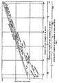
- FIGURE 3 the energy generated by preferred gas guns of the present invention is compared to dynamite charges of the prior art. Based on the empirical data shown in FIGURE 3, a 1.63 x 10 -4 m 3 (10 cubic inch) air gun is equivalent in energy to 0.045N (0.01 pounds) of 60% dynamite; and an 1.30 x 10 -3 m 3 (80 cubic inch) gas gun is equivalent to about 0.45N (0.1 pounds) of 60% dynamite. Downhole guns with a capacity of 1.63 x 10 -2 m 3 (1,000 cubic inches) provide energy equivalent to about 4.5N (1.0 pounds) of 60% dynamite. FIGURE 3 also compares the energy provided by a preferred electrical arc generator.
- sparkers provide energy approximately equal to a 8.19 x 10 -5 m 3 (5 cubic inch) gas gun or about 0.013N (0.003 pounds) of 60% dynamite.
- the correlations provided in FIGURE 3 confirm, on the basis of available and empirical data, that the non-destructive energy available through use of present invention is equivalent in terms of magnitude and volume to the energy available from explosive sources of the prior art.
- the percussive impact of the waveform energy can be used in conjunction with injection of various fluids, solvents, and reagents suitable for use in the presence of water sources to increase mechanical agitation.
- steam can be utilized as a compressed gas at temperatures and contact times beyond the tolerable limits of biologicals, which are then dislodged by percussive impact.
- the various combinations of waveform energies can be utilized alone or in conjunction one with the other, without deviating from the invention disclosed herein.
Landscapes
- Life Sciences & Earth Sciences (AREA)
- Engineering & Computer Science (AREA)
- Geology (AREA)
- Mining & Mineral Resources (AREA)
- Environmental & Geological Engineering (AREA)
- Geochemistry & Mineralogy (AREA)
- Physics & Mathematics (AREA)
- Fluid Mechanics (AREA)
- General Life Sciences & Earth Sciences (AREA)
- Health & Medical Sciences (AREA)
- Marine Sciences & Fisheries (AREA)
- Hydrology & Water Resources (AREA)
- Public Health (AREA)
- Water Supply & Treatment (AREA)
- Drilling And Exploitation, And Mining Machines And Methods (AREA)
- Physical Water Treatments (AREA)
- Organic Low-Molecular-Weight Compounds And Preparation Thereof (AREA)
- Earth Drilling (AREA)
- Physical Or Chemical Processes And Apparatus (AREA)
- Aeration Devices For Treatment Of Activated Polluted Sludge (AREA)
- Treatment Of Water By Ion Exchange (AREA)
- Extraction Or Liquid Replacement (AREA)
Claims (11)
- Ein Verfahren, um die Förderleistung von Wasserbrunnen zu stimulieren, die Folgendes beinhaltet:die Bereitstellung eines Wasserbrunnens (42), wobei der besagte Brunnen eine Bohrung ausweist, in die besagte Bohrung sind Vorrichtungen (10) zur Erzeugung von gasförmigen Druckwellenformen und zur Massenverlagerung durch die besagt Bohrung eingelassen, wobei die besagte Vorrichtungen (10) zur Wellenform-Erzeugung aus der Gruppe ausgewählt werden, zu welcher wenigstens ein schlagendes, gasbelüftetes Gerät (16, 18, 20, 22), wenigstens ein Dampf erzeugender Elektrolichtbogengenerator, sowie Kombinationen aus ihnen gehören;die Aktivierung der besagten Erzeugungs-Vorrichtungen, wobei Behinderungen der Förderleistung des Brunnens durch die Interaktion mit den besagten Wellenformen aus dem Weg geräumt werden; welches dadurch charakterisiert ist, dass der Effekt der besagten Wellenformen durch den Einsatz von Videoausrüstungen, Ausrüstung zur Messung des Bohrungsdurchmessers oder durch eine Kombination der besagten Ausrüstungen überwacht wird; und die Einstellung von Frequenz und Amplitude der erzeugten Wellenform, um den Eigenschaften der Brunnenfunktion zu entsprechen.
- Das Verfahren, wie es in Anspruch 1 definiert worden ist, bei welchem die besagte Vorrichtung zur Wellenform-Erzeugung ein schlagendes, gasbelüftetes Gerät (16, 18, 20, 22) ist
- Das Verfahren, wie es in Anspruch 2 definiert worden ist, bei welchem das besagte Gerät aktiviert wird, um etwa 1,63 x 10⁻⁵ - 0,245 m3 (1-15.000 Kubik-Inch) Gas mit einem Druck von etwa 1,72 x 10⁶ - 6,89 x 10⁷ Pa (250-10.000 psi) zur Verfügung zu stellen.
- Das Verfahren, wie es in Anspruch 3 definiert worden ist, bei welchem das besagte Gerät etwa 1,63 x 10⁻⁴ - 1,63 x 10⁻² m3 (10-1.000 Kubik-Inch) zur Verfügung stellt.
- Das Verfahren, wie es in Anspruch 4 definiert worden ist, bei welchem das besagte Gas mit einem Druck von etwa 3,44 x 10⁶ - 2,07 x 10⁷ Pa (500-3.000 psi) zur Verfügung gestellt wird.
- Das Verfahren, wie es in Anspruch 3 definiert worden ist, bei welchem das besagte Gerät in Intervallen von etwa 1 - 120 Sekunden aktiviert wird.
- Das Verfahren, wie es in Anspruch 6 definiert worden ist, bei welchem das besagte Aktivierungsintervall etwa 3 - 100 Sekunden lang ist.
- Das Verfahren, wie es in Anspruch1 definiert worden ist, bei welchem die besagte Vorrichtung zu Wellenform-Erzeugung ein Elektrolichtbogengenerator ist.
- Das Verfahren, wie es in Anspruch 8 definiert worden ist, bei welchem der besagte Generator in Intervallen von etwa 2 - 10 Sekunden aktiviert wird.
- Das Verfahren, wie es in Anspruch 1 definiert worden ist, bei welchem die besagte Vorrichtung zu Wellenform-Erzeugung aus einer Vielzahl von gasbelüfteten Geräten besteht.
- Das Verfahren, wie es in Anspruch 1 definiert worden ist, bei welchem die besagte Erzeugungs-Vorrichtung eine Kombination aus wenigstens einem gasbelüfteten Gerät und wenigstens einem Dampf erzeugenden Elektrolichtbogengenerator ist.
Applications Claiming Priority (3)
| Application Number | Priority Date | Filing Date | Title |
|---|---|---|---|
| US08/385,184 US5579845A (en) | 1995-02-07 | 1995-02-07 | Method for improved water well production |
| US385184 | 1995-02-07 | ||
| PCT/US1996/001782 WO1996024746A1 (en) | 1995-02-07 | 1996-02-07 | Method for improved water well production |
Publications (3)
| Publication Number | Publication Date |
|---|---|
| EP0819207A1 EP0819207A1 (de) | 1998-01-21 |
| EP0819207A4 EP0819207A4 (de) | 1999-01-27 |
| EP0819207B1 true EP0819207B1 (de) | 2003-06-25 |
Family
ID=23520378
Family Applications (1)
| Application Number | Title | Priority Date | Filing Date |
|---|---|---|---|
| EP96906354A Expired - Lifetime EP0819207B1 (de) | 1995-02-07 | 1996-02-07 | Verfahren zur entnahme von wasser aus einem brunnen |
Country Status (10)
| Country | Link |
|---|---|
| US (1) | US5579845A (de) |
| EP (1) | EP0819207B1 (de) |
| AT (1) | ATE243797T1 (de) |
| AU (1) | AU714358B2 (de) |
| CA (1) | CA2212411C (de) |
| DE (1) | DE69628825T2 (de) |
| DK (1) | DK0819207T3 (de) |
| ES (1) | ES2202429T3 (de) |
| PT (1) | PT819207E (de) |
| WO (1) | WO1996024746A1 (de) |
Families Citing this family (17)
| Publication number | Priority date | Publication date | Assignee | Title |
|---|---|---|---|---|
| US5836393A (en) * | 1997-03-19 | 1998-11-17 | Johnson; Howard E. | Pulse generator for oil well and method of stimulating the flow of liquid |
| IL126150A0 (en) | 1998-09-09 | 1999-05-09 | Prowell Technologies Ltd | Gas impulse device and method of use thereof |
| EP1234095A1 (de) * | 1999-11-29 | 2002-08-28 | Shell Internationale Researchmaatschappij B.V. | Verfahren zur verbesserung der permeabilität einer erdformation |
| BR0109642A (pt) * | 2000-03-29 | 2003-04-22 | Richard C Jackson | Método para o aperfeiçoamento da qualidade de um poço |
| US6533035B2 (en) | 2001-04-24 | 2003-03-18 | Layne Christensen Company | Method and apparatus for stimulating well production |
| DE102006040956B4 (de) * | 2006-08-31 | 2021-10-07 | Alexander Steinbrecher | Impulsgenerator |
| US7770638B2 (en) * | 2008-08-19 | 2010-08-10 | Flow Industries Ltd. | Method for completion, maintenance and stimulation of oil and gas wells |
| DE102010010181B3 (de) * | 2010-03-03 | 2011-07-21 | Teftorec GmbH, 47445 | Vorrichtung und Verfahren zum Erzeugen von Hochdruck-Impulsen |
| US20140196891A1 (en) * | 2013-01-16 | 2014-07-17 | Flow Industries, Ltd. | Self-contained gas impulse creation |
| CA2910902C (en) * | 2013-04-30 | 2020-07-21 | Ventora Technologies Ag | Device for cleaning water wells |
| US8706419B1 (en) | 2013-05-14 | 2014-04-22 | William C. Frazier | System and method for monitoring the change in permeability of a water well |
| CN103982168B (zh) * | 2014-04-21 | 2017-02-15 | 中北大学 | 井下多级智能高压气体脉冲压裂地层装置及其方法 |
| EP2977545B1 (de) * | 2014-07-24 | 2019-06-05 | Blue Spark Energy Inc. | Verfahren und Vorrichtung zur Reinigung von Kontrollpartikeln in einem Bohrloch |
| CN105201483A (zh) * | 2015-09-22 | 2015-12-30 | 中北大学 | 环保型井下压裂地层方法 |
| CA3091247A1 (en) * | 2019-09-06 | 2021-03-06 | Optimum Petroleum Services Inc. | Downhole pressure wave generating device |
| FR3130872B1 (fr) | 2021-12-21 | 2023-11-10 | Forapulse | Dispositif de nettoyage et de régénération pour équipement de forage |
| US12378845B2 (en) * | 2022-10-12 | 2025-08-05 | Airburst Technology, Llc | System and method for rehabilitating a water well with compressed nitrogen |
Family Cites Families (6)
| Publication number | Priority date | Publication date | Assignee | Title |
|---|---|---|---|---|
| US3702635A (en) * | 1970-11-10 | 1972-11-14 | Amoco Prod Co | Seismic energy source using liquid explosive |
| US4040486A (en) * | 1976-05-10 | 1977-08-09 | Steve Taylor | Method and apparatus for air development and rejuvenation of water wells |
| US4345650A (en) * | 1980-04-11 | 1982-08-24 | Wesley Richard H | Process and apparatus for electrohydraulic recovery of crude oil |
| JPH03500671A (ja) * | 1988-05-20 | 1991-02-14 | プロエクトノ‐コンストルクトルスコエ ビュロ エレクトロギドラフリキ アカデミイ ナウク ウクラインスコイ エスエスエル | 石油生産法に於ける抗井刺激方法及びその方法を実施するための装置 |
| US4997044A (en) * | 1989-12-01 | 1991-03-05 | Stack Walter E | Apparatus for generating hydraulic shock waves in a well |
| US5297631A (en) * | 1993-04-07 | 1994-03-29 | Fleet Cementers, Inc. | Method and apparatus for downhole oil well production stimulation |
-
1995
- 1995-02-07 US US08/385,184 patent/US5579845A/en not_active Expired - Lifetime
-
1996
- 1996-02-07 PT PT96906354T patent/PT819207E/pt unknown
- 1996-02-07 ES ES96906354T patent/ES2202429T3/es not_active Expired - Lifetime
- 1996-02-07 EP EP96906354A patent/EP0819207B1/de not_active Expired - Lifetime
- 1996-02-07 CA CA002212411A patent/CA2212411C/en not_active Expired - Lifetime
- 1996-02-07 WO PCT/US1996/001782 patent/WO1996024746A1/en not_active Ceased
- 1996-02-07 AT AT96906354T patent/ATE243797T1/de active
- 1996-02-07 DE DE69628825T patent/DE69628825T2/de not_active Expired - Lifetime
- 1996-02-07 DK DK96906354T patent/DK0819207T3/da active
- 1996-02-07 AU AU49763/96A patent/AU714358B2/en not_active Ceased
Also Published As
| Publication number | Publication date |
|---|---|
| US5579845A (en) | 1996-12-03 |
| EP0819207A4 (de) | 1999-01-27 |
| ES2202429T3 (es) | 2004-04-01 |
| PT819207E (pt) | 2003-11-28 |
| EP0819207A1 (de) | 1998-01-21 |
| CA2212411C (en) | 2002-07-02 |
| DK0819207T3 (da) | 2003-10-20 |
| AU4976396A (en) | 1996-08-27 |
| DE69628825D1 (de) | 2003-07-31 |
| WO1996024746A1 (en) | 1996-08-15 |
| DE69628825T2 (de) | 2004-05-13 |
| ATE243797T1 (de) | 2003-07-15 |
| AU714358B2 (en) | 1999-12-23 |
| CA2212411A1 (en) | 1996-08-15 |
Similar Documents
| Publication | Publication Date | Title |
|---|---|---|
| EP0819207B1 (de) | Verfahren zur entnahme von wasser aus einem brunnen | |
| WO1996024746A9 (en) | Method for improved water well production | |
| US4164978A (en) | Oil extraction method | |
| US10746006B2 (en) | Plasma sources, systems, and methods for stimulating wells, deposits and boreholes | |
| US5836393A (en) | Pulse generator for oil well and method of stimulating the flow of liquid | |
| RU2310067C2 (ru) | Способ и устройства для создания в стволе скважины состояния переходного давления | |
| US7264055B2 (en) | Apparatus and method of applying force to a stuck object in a wellbore | |
| US5297631A (en) | Method and apparatus for downhole oil well production stimulation | |
| RU2075593C1 (ru) | Устройство для вскрытия и обработки призабойной зоны скважин | |
| US2307729A (en) | Well explosive | |
| EP0925423A1 (de) | Vorrichtung und verfahren zum perforieren und stimulieren einer gesteinsformation | |
| US3796463A (en) | Process and apparatus for mining by hydroelectric pulsed liquid jets | |
| RU2103493C1 (ru) | Способ обработки продуктивного пласта | |
| RU2211920C2 (ru) | Способ гидроразрыва пласта и повышения проницаемости горных пород и оборудование для его осуществления (варианты) | |
| RU2105874C1 (ru) | Способ обработки призабойной зоны пласта скважин | |
| RU2478780C1 (ru) | Способ добычи редких металлов по технологии подземного скважинного выщелачивания и устройство для его реализации | |
| US3881559A (en) | Method for stress wave drilling | |
| RU2014456C1 (ru) | Способ скважинной гидродобычи полезных ископаемых | |
| US4394051A (en) | Method of hydrospalling | |
| RU2147337C1 (ru) | Способ обработки призабойной зоны пласта скважины и погружной генератор для его осуществления | |
| RU2176403C1 (ru) | Устройство и способ возбуждения упругих колебаний и гидроразрыва пласта | |
| RU2057910C1 (ru) | Устройство для перфорации скважин | |
| CN117631015B (zh) | 一种用于钻孔长期监测的可控震源及操作方法 | |
| RU2194848C1 (ru) | Устройство для депрессионной перфорации скважин | |
| RU2250986C2 (ru) | Способ повышения продуктивности скважин |
Legal Events
| Date | Code | Title | Description |
|---|---|---|---|
| PUAI | Public reference made under article 153(3) epc to a published international application that has entered the european phase |
Free format text: ORIGINAL CODE: 0009012 |
|
| 17P | Request for examination filed |
Effective date: 19970905 |
|
| AK | Designated contracting states |
Kind code of ref document: A1 Designated state(s): AT BE CH DE DK ES FR GB IE IT LI NL PT SE |
|
| RBV | Designated contracting states (corrected) |
Designated state(s): AT BE CH DE DK ES FR GB IE IT LI NL PT SE |
|
| A4 | Supplementary search report drawn up and despatched |
Effective date: 19981216 |
|
| AK | Designated contracting states |
Kind code of ref document: A4 Designated state(s): AT BE CH DE DK ES FR GB IE IT LI NL PT SE |
|
| RHK1 | Main classification (correction) |
Ipc: E03B 3/15 |
|
| 17Q | First examination report despatched |
Effective date: 20010817 |
|
| GRAH | Despatch of communication of intention to grant a patent |
Free format text: ORIGINAL CODE: EPIDOS IGRA |
|
| GRAH | Despatch of communication of intention to grant a patent |
Free format text: ORIGINAL CODE: EPIDOS IGRA |
|
| GRAA | (expected) grant |
Free format text: ORIGINAL CODE: 0009210 |
|
| AK | Designated contracting states |
Designated state(s): AT BE CH DE DK ES FR GB IE IT LI NL PT SE |
|
| PG25 | Lapsed in a contracting state [announced via postgrant information from national office to epo] |
Ref country code: LI Free format text: LAPSE BECAUSE OF FAILURE TO SUBMIT A TRANSLATION OF THE DESCRIPTION OR TO PAY THE FEE WITHIN THE PRESCRIBED TIME-LIMIT Effective date: 20030625 Ref country code: CH Free format text: LAPSE BECAUSE OF FAILURE TO SUBMIT A TRANSLATION OF THE DESCRIPTION OR TO PAY THE FEE WITHIN THE PRESCRIBED TIME-LIMIT Effective date: 20030625 |
|
| REG | Reference to a national code |
Ref country code: GB Ref legal event code: FG4D |
|
| REG | Reference to a national code |
Ref country code: CH Ref legal event code: EP |
|
| REG | Reference to a national code |
Ref country code: IE Ref legal event code: FG4D |
|
| REF | Corresponds to: |
Ref document number: 69628825 Country of ref document: DE Date of ref document: 20030731 Kind code of ref document: P |
|
| REG | Reference to a national code |
Ref country code: SE Ref legal event code: TRGR |
|
| REG | Reference to a national code |
Ref country code: CH Ref legal event code: PL |
|
| REG | Reference to a national code |
Ref country code: ES Ref legal event code: FG2A Ref document number: 2202429 Country of ref document: ES Kind code of ref document: T3 |
|
| PLBE | No opposition filed within time limit |
Free format text: ORIGINAL CODE: 0009261 |
|
| STAA | Information on the status of an ep patent application or granted ep patent |
Free format text: STATUS: NO OPPOSITION FILED WITHIN TIME LIMIT |
|
| ET | Fr: translation filed | ||
| 26N | No opposition filed |
Effective date: 20040326 |
|
| REG | Reference to a national code |
Ref country code: FR Ref legal event code: CL Name of requester: CIRRUS AQUA LIMITED, GB Effective date: 20111020 |
|
| REG | Reference to a national code |
Ref country code: GB Ref legal event code: 732E Free format text: REGISTERED BETWEEN 20111117 AND 20111123 |
|
| PGFP | Annual fee paid to national office [announced via postgrant information from national office to epo] |
Ref country code: IE Payment date: 20120224 Year of fee payment: 17 |
|
| PGFP | Annual fee paid to national office [announced via postgrant information from national office to epo] |
Ref country code: PT Payment date: 20120119 Year of fee payment: 17 Ref country code: DE Payment date: 20120228 Year of fee payment: 17 |
|
| PGFP | Annual fee paid to national office [announced via postgrant information from national office to epo] |
Ref country code: SE Payment date: 20120228 Year of fee payment: 17 Ref country code: DK Payment date: 20120224 Year of fee payment: 17 Ref country code: BE Payment date: 20120227 Year of fee payment: 17 Ref country code: IT Payment date: 20120224 Year of fee payment: 17 |
|
| PGFP | Annual fee paid to national office [announced via postgrant information from national office to epo] |
Ref country code: NL Payment date: 20120228 Year of fee payment: 17 |
|
| PGFP | Annual fee paid to national office [announced via postgrant information from national office to epo] |
Ref country code: AT Payment date: 20120119 Year of fee payment: 17 |
|
| PGFP | Annual fee paid to national office [announced via postgrant information from national office to epo] |
Ref country code: ES Payment date: 20120227 Year of fee payment: 17 |
|
| REG | Reference to a national code |
Ref country code: PT Ref legal event code: MM4A Free format text: LAPSE DUE TO NON-PAYMENT OF FEES Effective date: 20130807 |
|
| BERE | Be: lapsed |
Owner name: *FRAZIER WILLIAM C. Effective date: 20130228 |
|
| REG | Reference to a national code |
Ref country code: NL Ref legal event code: V1 Effective date: 20130901 |
|
| REG | Reference to a national code |
Ref country code: DK Ref legal event code: EBP |
|
| REG | Reference to a national code |
Ref country code: SE Ref legal event code: EUG |
|
| REG | Reference to a national code |
Ref country code: AT Ref legal event code: MM01 Ref document number: 243797 Country of ref document: AT Kind code of ref document: T Effective date: 20130228 |
|
| PG25 | Lapsed in a contracting state [announced via postgrant information from national office to epo] |
Ref country code: PT Free format text: LAPSE BECAUSE OF NON-PAYMENT OF DUE FEES Effective date: 20130807 Ref country code: AT Free format text: LAPSE BECAUSE OF NON-PAYMENT OF DUE FEES Effective date: 20130228 Ref country code: SE Free format text: LAPSE BECAUSE OF NON-PAYMENT OF DUE FEES Effective date: 20130208 Ref country code: NL Free format text: LAPSE BECAUSE OF NON-PAYMENT OF DUE FEES Effective date: 20130901 |
|
| REG | Reference to a national code |
Ref country code: IE Ref legal event code: MM4A |
|
| REG | Reference to a national code |
Ref country code: DE Ref legal event code: R119 Ref document number: 69628825 Country of ref document: DE Effective date: 20130903 |
|
| PG25 | Lapsed in a contracting state [announced via postgrant information from national office to epo] |
Ref country code: IT Free format text: LAPSE BECAUSE OF NON-PAYMENT OF DUE FEES Effective date: 20130207 |
|
| PG25 | Lapsed in a contracting state [announced via postgrant information from national office to epo] |
Ref country code: DE Free format text: LAPSE BECAUSE OF NON-PAYMENT OF DUE FEES Effective date: 20130903 Ref country code: BE Free format text: LAPSE BECAUSE OF NON-PAYMENT OF DUE FEES Effective date: 20130228 Ref country code: DK Free format text: LAPSE BECAUSE OF NON-PAYMENT OF DUE FEES Effective date: 20130228 Ref country code: IE Free format text: LAPSE BECAUSE OF NON-PAYMENT OF DUE FEES Effective date: 20130207 |
|
| REG | Reference to a national code |
Ref country code: ES Ref legal event code: FD2A Effective date: 20140408 |
|
| PG25 | Lapsed in a contracting state [announced via postgrant information from national office to epo] |
Ref country code: ES Free format text: LAPSE BECAUSE OF NON-PAYMENT OF DUE FEES Effective date: 20130208 |
|
| REG | Reference to a national code |
Ref country code: FR Ref legal event code: PLFP Year of fee payment: 20 |
|
| PGFP | Annual fee paid to national office [announced via postgrant information from national office to epo] |
Ref country code: FR Payment date: 20150217 Year of fee payment: 20 Ref country code: GB Payment date: 20150226 Year of fee payment: 20 |
|
| REG | Reference to a national code |
Ref country code: GB Ref legal event code: PE20 Expiry date: 20160206 |
|
| PG25 | Lapsed in a contracting state [announced via postgrant information from national office to epo] |
Ref country code: GB Free format text: LAPSE BECAUSE OF EXPIRATION OF PROTECTION Effective date: 20160206 |