EP0819395A2 - Regal - Google Patents
Regal Download PDFInfo
- Publication number
- EP0819395A2 EP0819395A2 EP97202222A EP97202222A EP0819395A2 EP 0819395 A2 EP0819395 A2 EP 0819395A2 EP 97202222 A EP97202222 A EP 97202222A EP 97202222 A EP97202222 A EP 97202222A EP 0819395 A2 EP0819395 A2 EP 0819395A2
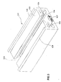
- Authority
- EP
- European Patent Office
- Prior art keywords
- support
- shelf
- shelf according
- holding means
- board
- Prior art date
- Legal status (The legal status is an assumption and is not a legal conclusion. Google has not performed a legal analysis and makes no representation as to the accuracy of the status listed.)
- Granted
Links
Images




Classifications
-
- A—HUMAN NECESSITIES
- A47—FURNITURE; DOMESTIC ARTICLES OR APPLIANCES; COFFEE MILLS; SPICE MILLS; SUCTION CLEANERS IN GENERAL
- A47B—TABLES; DESKS; OFFICE FURNITURE; CABINETS; DRAWERS; GENERAL DETAILS OF FURNITURE
- A47B96/00—Details of cabinets, racks or shelf units not covered by a single one of groups A47B43/00 - A47B95/00; General details of furniture
- A47B96/02—Shelves
- A47B96/025—Shelves with moving elements, e.g. movable extensions or link elements
-
- A—HUMAN NECESSITIES
- A47—FURNITURE; DOMESTIC ARTICLES OR APPLIANCES; COFFEE MILLS; SPICE MILLS; SUCTION CLEANERS IN GENERAL
- A47B—TABLES; DESKS; OFFICE FURNITURE; CABINETS; DRAWERS; GENERAL DETAILS OF FURNITURE
- A47B57/00—Cabinets, racks or shelf units, characterised by features for adjusting shelves or partitions
- A47B57/58—Cabinets, racks or shelf units, characterised by features for adjusting shelves or partitions with means for adjusting partitions horizontally
- A47B57/583—Cabinets, racks or shelf units, characterised by features for adjusting shelves or partitions with means for adjusting partitions horizontally by sliding
-
- A—HUMAN NECESSITIES
- A47—FURNITURE; DOMESTIC ARTICLES OR APPLIANCES; COFFEE MILLS; SPICE MILLS; SUCTION CLEANERS IN GENERAL
- A47B—TABLES; DESKS; OFFICE FURNITURE; CABINETS; DRAWERS; GENERAL DETAILS OF FURNITURE
- A47B57/00—Cabinets, racks or shelf units, characterised by features for adjusting shelves or partitions
- A47B57/58—Cabinets, racks or shelf units, characterised by features for adjusting shelves or partitions with means for adjusting partitions horizontally
- A47B57/583—Cabinets, racks or shelf units, characterised by features for adjusting shelves or partitions with means for adjusting partitions horizontally by sliding
- A47B57/585—Cabinets, racks or shelf units, characterised by features for adjusting shelves or partitions with means for adjusting partitions horizontally by sliding with connection means slidable in a rail
-
- A—HUMAN NECESSITIES
- A47—FURNITURE; DOMESTIC ARTICLES OR APPLIANCES; COFFEE MILLS; SPICE MILLS; SUCTION CLEANERS IN GENERAL
- A47B—TABLES; DESKS; OFFICE FURNITURE; CABINETS; DRAWERS; GENERAL DETAILS OF FURNITURE
- A47B96/00—Details of cabinets, racks or shelf units not covered by a single one of groups A47B43/00 - A47B95/00; General details of furniture
- A47B96/06—Brackets or similar supporting means for cabinets, racks or shelves
-
- A—HUMAN NECESSITIES
- A47—FURNITURE; DOMESTIC ARTICLES OR APPLIANCES; COFFEE MILLS; SPICE MILLS; SUCTION CLEANERS IN GENERAL
- A47B—TABLES; DESKS; OFFICE FURNITURE; CABINETS; DRAWERS; GENERAL DETAILS OF FURNITURE
- A47B96/00—Details of cabinets, racks or shelf units not covered by a single one of groups A47B43/00 - A47B95/00; General details of furniture
- A47B96/06—Brackets or similar supporting means for cabinets, racks or shelves
- A47B96/063—C-shaped brackets for gripping the shelf edge
Definitions
- the present invention relates to a shelf according to the preamble of claim 1.
- Shelf holders of a known type consist of a horizontal support surface and a support surface perpendicular to the former, which is fastened to a vertical construction, usually to a wall.
- a support e.g. arranged in the form of a board, which must be supported by at least one further shelf holder depending on the weight and longitudinal extent of the loads to be supported.
- the support surface must also have a depth or a support length that must be at least equal to the distance of the center of gravity of the support from the innermost support point of the support itself in the case where the support is only very simply placed: otherwise the support must be attached to the shelf holder or for them it is not possible to use an overhanging holder.
- One of the objects of the present invention is therefore to propose a shelf that should allow the use of a shelf even in the case where there was a risk of tipping over for the shelf holders of a known type.
- Another object is to propose a shelf bracket solution in such a way that it can be produced in one piece, simple in arrangement and by means of a plastic mold.
- Another object of the present invention is also to meet the need for adjustability of shelf brackets and to propose a guiding and carrying device which enables the shelf brackets to be adjusted in the horizontal direction, above all in terms of height, but depending on the arrangement of the device .
- Another object of the present invention is to provide this guiding and carrying device directly on a new type of rack holder.
- a shelf holder can be easily adjusted along the sliding surface and, should the height be adjusted, the shelf holder itself can be attached in a fixed position.
- the rack holder is held in its adjustment within two lateral guides.
- the fixing between the shelf holder and the guide and carrying device is ensured by a screw which loads the shoulder against the undercut of the heel.
- a solution suitable for executing the guide and support device in plastic is provided according to the invention by claim 9, with complicated slides being avoided for the injection molds and thus saving on the production costs of the injection mold and on the machining itself.
- the guide and support device can be conveniently attached to a wall, for example, since it is provided with bores for receiving screws for fastening to the wall.
- the solution according to claim 11 is provided for shelf dividing elements.
- reference number 1 generally indicates the holder according to the invention. It has a support surface 2 and a receptacle 3 for a fastener.
- the receptacle is formed by a hole for a screw.
- a holding means in the form of a gripping plane 4 extends above the support, parallel to the same.
- the support 2 and the gripping plane 4 are connected to one another via a web 6. In the latter, the recording 3 is worked out.
- the support 2 is formed by a wall of a hollow section 7 of the holder 1, whose side walls 10 merge into side walls of the web 6, which in turn merge into side walls of a hollow section 8, the surface of which forms the gripping plane 4.
- the common walls have a circumferential support edge 12 which on a vertical construction, for example on a wall.
- the support edge 12 is also the opening edge of the communicating recesses of the hollow sections 7 and 8.
- the receptacle 3 in turn has an edge 13 which is flush with the supporting edge 12.
- the hollow section 7 has a front wall 14 which connects the front edge of the support 2 to the lower edge 12 in an arc, and the hollow section 8 also has a front wall 15 which connects the front edge of the gripping plane 4 to the upper support edge 12.
- the fastening means could consist of several screws or be formed from hooks of a known type.
- the formation of the hollow sections could also be polygonal or straight.
- the materials themselves can be any, in the case of plastics e.g. made of reinforced polyamide 6. Material reinforcements such as webs within the recesses can be provided, as well as given by the teaching of the prior art.
- reference number 101 generally indicates a guide and support device for support and separating elements for shelves according to the invention.
- the device 101 has a sliding plane 102, which has a bearing surface e.g. for the shelf holder described above.
- the sliding plane is interrupted in the longitudinal direction by a gap 103, which is followed by an undercut 104 parallel to the sliding plane 102, which in turn is closed at the bottom, with the provision of possible cutouts 105, by a wall 106.
- the wall 106 is expediently provided with bores 107 which receive fastening screws, not shown, in order to mount the device 101 e.g. to attach to a wall.
- the sliding plane 102 is preferably laterally delimited by two projections 108 which form a guide for the shelf holder.
- the gap 103 is designed to positively accommodate a connecting section 109 of a fastening element 110, which is also provided below the connecting section 109 with a shoulder 111 which slides along the undercut 104.
- the fastening element 110 is also provided with a threaded bore 112, into which a fastening screw (not shown) of the shelf holder of the fastening element 110 can be screwed, which thus acts as a screw nut.
- FIG. 4 shows an embodiment which is particularly indicated for the production of the guide and support device in plastic.
- the wall 106 has openings 112, while the sliding plane 102 is interrupted by gaps 113 for the passage of the projections of the other mold half for executing the connecting webs between the side walls 114 of the device 101 and the wall 106 via the webs 115 is.
- a shelf holder 115 is shown in order to take up the thickness of a board, not shown, of a known type of support with its arms 116 and 117.
- the shelf holder essentially has an undercut guide 118 on its upper side of the arm 116 in order to accommodate the lower extension 119 of a separating element 120 as a stop or as an end wall for a shelf.
Landscapes
- Assembled Shelves (AREA)
- Devices For Medical Bathing And Washing (AREA)
- Memory System Of A Hierarchy Structure (AREA)
- Liquid Crystal (AREA)
- Devices For Use In Laboratory Experiments (AREA)
- Furniture Connections (AREA)
- Moulds For Moulding Plastics Or The Like (AREA)
- Polishing Bodies And Polishing Tools (AREA)
- Centrifugal Separators (AREA)
- Supports Or Holders For Household Use (AREA)
- Clamps And Clips (AREA)
Abstract
Description
- Die vorliegende Erfindung bezieht sich auf ein Regal gemäß dem Oberbegriff des Anspruchs 1.
- Regalhalter bekannter Art bestehen aus einer horizontalen Auflagefläche und aus einer zur ersteren senkrechten Stützfläche, die an einer senkrechten Konstruktion, üblicherweise an einer Wand befestigt wird.
- An der Auflagefläche wird eine Auflage z.B. in der Form eines Brettes angeordnet, das je nach Gewicht und Längsausdehnung der abzustützenden Lasten durch mindestens einen weiteren Regalhalter abgestützt werden muß. Die Auflagefläche muß überdies eine Tiefe bzw. eine Auflagelänge aufweisen, die mindestens gleich dem Abstand des Schwerpunktes der Auflage vom innersten Auflagepunkt der Auflage selbst im Fall sein muß, wo die Auflage nur ganz einfach aufgelegt ist: andernfalls muß die Auflage am Regalhalter befestigt werden oder für sie ist es nicht möglich einen auskragenden Halter zu verwenden.
- In einigen Fällen besteht das Problem, die Regalhalter rasch und mit Verstellmöglichkeit vor allem höhenmäßig zu befestigen. Dieses Problem besteht jedoch auch für Regalhalter anderer Art. So stellt sich auch das Problem, an den Auflagen von Regalen Trennelemente sowohl in regelbarer als auch fester Weise anbringen zu können.
- Eine der Aufgaben der vorliegenden Erfindung besteht daher darin, ein Regal vorzuschlagen, das die Verwendung eines Regalbrettes auch im Falle erlauben soll, wo für die Regalhalter bekannter Art eine Kippgefahr bestand.
- Eine weitere Aufgabe liegt darin, eine Regalhalterkonsolution derart vorzuschlagen, daß sie einstückig, einfach in der Anordnung und mittels einer Kunststoffgießform herstellbar ist.
- Eine weitere Aufgabe der vorliegenden Erfindung besteht auch darin, dem Bedürfnis der Einstellbarkeit von Regalhaltern nachzukommen und eine Führungs- und Trageinrichtung vorzuschlagen, die es den Regalhaltern ermöglicht, vor allem höhenmäßig, jedoch je nach der Anordnung der Einrichtung, auch in horizontaler Richtung eingestellt zu werden.
- Eine weitere Aufgabe der vorliegenden Erfindung besteht darin, diese Führungs- und Trageinrichtung unmittelbar an einem Regalhalter neuer Art vorzusehen.
- Diese Aufgaben werden durch ein Regal mit den kennzeichnenden Merkmalen des Anspruches 1 und 6 gelöst.
- Indem eine "zangenartige" Konstruktion vorgeschlagen wird, ist es möglich den Randbereich einer Auflage im wesentlichen formschlüssig derart aufzunehmen, daß die Auflage selbst stabil gehalten wird, ohne daß irgendeine Notwendigkeit bestünde, die Auflage am Regalhalter zu befestigen, um sowohl eine Verstellung der Auflage als auch ein Kippen zu verhindern, sobald der Schwerpunkt der Gesamtheit der Auflage/Last sich außerhalb des Auflagebereiches befindet.
- Wird ein Steg gemäß Anspruch 2 zur Herstellung der Aufnahme oder der Aufnahmen für die Befestigungsschrauben verwendet, so sind die Schrauben für die Montage und Demontage leicht zugänglich.
- Besonders bevorzugt ist die Ausbildung des Regalhalters nach Anspruch 3, bei dem die Kupplungsaufnahme gleichzeitig mit der Konstruktion der Auflageebene und der Halteebene in einem einzigen Spritzgußvorgang ausgeführt wird.
- Gemäß Anspruch 6 kann ein Regalhalter bequem längs der Gleitfläche verstellt werden und, sollte die Einstellung höhenmäßig erfolgen, kann der Regalhalter selbst in einer festen Position befestigt werden.
- In einer Ausführungsform ist der Regalhalter in seiner Verstellung innerhalb zwei seitlichen Führungen gehalten.
- In einer weiteren Weiterbildung ist die Festlegung zwischen Regalhalter und Führungs- und Trageinrichtung durch eine Schraube sichergestellt, die die Schulter gegen die Hinterschneidung des Absatzes belastet.
- Eine zur Ausführung der Führungs- und Trageinrichtung in Kunststoff geeignete Lösung ist erfindungsgemäß durch Anspruch 9 gegeben, wobei für die Spritzgußformen komplizierte Schieber vermieden werden und so bei den Herstellungskosten der Spritzgießform sowie bei der Bearbeitung selbst gespart wird.
- In einer weiteren vorteilhaften Ausführung nach Anspruch 10, kann die Führungs- und Trageinrichtung bequem beispielsweise an einer Wand angebracht werden, da sie mit Bohrungen zur Aufnahme von Schrauben zur Befestigung an der Wand versehen ist.
- Für Regaltrennelemente ist die Lösung gemäß Anspruch 11 vorgesehen.
- Bauliche Einzelheiten des erfindungsgemäßen Regals ergeben sich aus der Beschreibung einer bevorzugten in der beigelegten Zeichnung dargestellten Ausführungsform. Es zeigen,
- Figur 1
- ein Schaubild eines erfindungsgemäßen Regalhalters,
- Figur 2
- einen Schnitt gemäß der Linie II-II aus Figur 1,
- Figur 3
- ein schematisches Schaubild eines Abschnittes der erfindungsgemäßen Einrichtung,
- Figur 4
- eine erfindungsgemäße Einrichtung in einem schematischen Schaubild teilweise aufgebrochen, in Kombination mit einem Verbindungsgleiter,
- Figur 5
- einen Regalhalter in einem Schaubild, versehen mit einer Führungseinrichtung, und
- Figur 6
- eine Stirnansicht eines Regalhalters wie aus Figur 5, an dem ein Trennelement oder eine Regalwand angebracht ist.
- Wie in den Figuren gezeigt, ist mit der Bezugsziffer 1 im allgemeinen der erfindungsgemäße Halter angegeben. Er weist eine Auflagefläche 2 und eine Aufnahme 3 für eine Befestigungsmittel auf. Im vorliegenden Fall ist die Aufnahme durch eine Bohrung für eine Schraube gebildet.
- Erfindungsgemäß erstreckt sich oberhalb der Auflage, parallel zu derselben, ein Haltemittel in der Form einer Greifebene 4.
- Die Auflage 2 und die Greifebene 4 sind miteinander über einen Steg 6 verbunden. In diesem letzteren ist die Aufnahme 3 ausgearbeitet.
- Die Auflage 2 wird durch eine Wand eines Hohlabschnittes 7 des Halters 1 gebildet, dessen Seitenwände 10 in Seitenwänden des Steges 6 übergehen, die ihrerseits in Seitenwänden eines Hohlabschnittes 8 übergehen, dessen Oberfläche die Greifebene 4 bildet. Die gemeinsamen Wände weisen einen umlaufende Stützrand 12 auf, die auf einer senkrechte Konstruktion, z.B. an einer Wand angesetzt werden kann. Der Stützrand 12 ist überdies der Öffnungsrand der kommunizierenden Ausnehmungen der Hohlabschnitte 7 und 8.
- Die Aufnahme 3 weist ihrerseits einen mit dem Stützrand 12 bündigen Rand 13 auf.
- Der Hohlabschnitt 7 weist eine Vorderwand 14 auf, die bogenförmig den Vorderrand der Auflage 2 mit dem unteren Rand 12 verbindet, sowie auch der Hohlabschnitt 8 eine Vorderwand 15 aufweist, die den Vorderrand der Greifebene 4 mit dem oberen Stützrand 12 verbindet.
- Zahlreiche Änderungen und Varianten können am beschriebenen erfindungsgemäßen Regalhalter vorgesehen sein, ohne den Schutzbereich zu verlassen: so z.B. könnten die Befestigungsmittel aus mehreren Schrauben bestehen oder auch aus Haken bekannter Art gebildet sein. Die Ausbildung der Hohlabschnitte könnte auch polygonal oder geradlinig sein. Die Werkstoffe selbst können beliebig sein, im Fall von Kunststoffen z.B. aus verstärktem Polyamid 6. Material verstärkungen wie Stege innerhalb der Ausnehmungen können vorgesehen sein, sowie durch die Lehre des Standes der Technik gegeben.
- In Figur 3 ist mit der Bezugsziffer 101 im allgemeinen eine Führungs- und Trageinrichtung für Trag- und Trennelemente für erfindungsgemäße Regale angegeben.
- Die Einrichtung 101 weist eine Gleitebene 102 auf, die eine Auflagefläche z.B. für den oben beschriebenen Regalhalter trägt. Die Gleitebene ist in Längsrichtung durch einen Spalt 103 unterbrochen, dem parallel zur Gleitebene 102 eine Hinterschneidung 104 folgt, die ihrerseits unten, mit Vorsehung von eventuellen Aussparungen 105, durch eine Wand 106 abgeschlossen ist. Zweckmäßigerweise ist die Wand 106 mit Bohrungen 107 versehen, die nicht gezeigte Befestigungsschrauben aufnehmen, um die Einrichtung 101 z.B. an einer Wand zu befestigen. Bevorzugterweise ist die Gleitebene 102 seitlich durch zwei Vorsprünge 108 begrenzt, die eine Führung für den Regalhalter bilden.
- Der Spalt 103 ist dazu ausgebildet, formflüssig einen Verbindungsabschnitt 109 eines Befestigungselementes 110 aufzunehmen, das überdies unterhalb des Verbindungsabschnittes 109 mit einem Absatz 111 versehen ist, der längs der Hinterschneidung 104 gleitet. Das Befestigungselement 110 ist überdies mit einer Gewindebohrung 112 versehen, in die eine nicht gezeigte Befestigungsschraube des Regalhalters des Befestigungselementes 110 eingeschraubt werden kann, das so als Schraubenmutter wirkt.
- In Figur 4 ist eine Ausführungsform dargestellt, die für die Herstellung der Führungs- und Trageinrichtung in Kunststoff besonders angezeigt ist. In diesem Falle weist nämlich zur Ausführung der Gleitebene 102 und für die Einführung des Kerns einer Spritzgießform zur Ausführung der Hinterschneidung 104, die Wand 106 Durchbrüche 112 auf, während die Gleitebene 102 durch Lücken 113 für den Durchgang der Vorsprünge der anderen Formhälfte zur Ausführung der Verbindungsstege zwischen den Seitenwänden 114 der Einrichtung 101 und der Wand 106 über die Stege 115 unterbrochen ist.
- In Figur 5 ist hingegen ein Regalhalter 115 dargestellt, um mit seinen Armen 116 und 117 die Dicke eines nicht dargestellten Brettes einer Auflage bekannter Art aufzunehmen. Der Regalhalter weist an seiner oberen Seite des Armes 116 im wesentlichen eine hinterschnittene Führung 118 auf, um die untere Erweiterung 119 eines Trennelementes 120 als Anschlag oder als Endwand für ein Regal aufzunehmen.
Claims (11)
- Regal, bestehend aus einer Auflage (2) zur Abstützung eines Brettes im Bereich seines Randes und aus Befestigungsmitteln zur festen Verbindung der Auflage (2) mit einer senkrechten Konstruktion,
dadurch gekennzeichnet, daß es ein Haltemittel (4) aufweist, das sich im wesentlichen parallel zur Auflage (2) und mit Abstand von derselben derart erstreckt, daß eine Kuppelaufnahme zum Brett derart gebildet wird, daß zwischen der Auflage (2) und dem Haltemittel (4) der Brettrand aufgenommen werden kann, wobei die Auflage und das Haltemittel (4) mittels eines Steges (6) miteinander verbunden sind. - Regal nach Anspruch 1, dadurch gekennzeichnet, daß der Steg (6) mit den genannten Befestigungsmitteln versehbar ist.
- Regal nach Anspruch 1, dadurch gekennzeichnet, daß die Auflage (2) und das Haltemittel (4) jeweils durch offene Hohlkörper (7,8) seitens der Ansetzung an der senkrechten Konsolution derart gebildet sind, daß Ausnehmungen ohne Hinterschneidungen gebildet werden, um Kernen einer Kunststoffgießform den gleichzeitigen Auszug in einer zur Auszugsrichtung eines Kerns derselben Form parallelen und entgegengesetzten Richtung zur Bildung einer den Brettrand aufnehmende Aufnahme (5) zu erlauben.
- Regal nach Anspruch 1, dadurch gekennzeichnet, daß im Steg (6) mit dem Auszugsvorgang der Form eine das Befestigungsmittel aufnehmende Bohrung (3) hergestellt wird.
- Regal nach Anspruch 1, dadurch gekennzeichnet, daß die Oberfläche der Auflage (2) und/oder jene (4) des Haltemittels mit Erhebungen versehen sind, die den Auszug des Brettes aus der Aufnahme (5) erschweren.
- Regal nach Anspruch 1 mit einer Führungs- und Trageinrichtung für Trag- und Trennelemente für Regale, umfassend Befestigungsmittel an einer Konstruktion, dadurch gekennzeichnet, daß die Führungs- und Trageinrichtung (101) die Konstruktion selbst ist und ein Profil mit einer Gleitebene (102) einer Auflagefläche für das Element aufweist, die in Längsrichtung durch einen Spalt (103) unterbrochen ist, der einen Verbindungsabschnitt (104) eines Befestigungsmittels (110) des Elements gleitbar aufnimmt, und mit einer Hinterschneidung des Spaltes gegenüber der Gleitebene unterhalb derselben zur Aufnahme eines Absatzes (111) des Verbindungsabschnittes (109), der andererseits fest mit dem Element selbst verbindbar ist, wobei der Absatz von einer Stellung, in der der Regalhalter auf der Ebene gleitbar ist, in eine Stellung verstellbar ist, in der der Absatz den Regalhalter selbst fest auf die Gleitebene derart drückt, daß das Element selbst sicher in Position gehalten wird.
- Regal nach Anspruch 6, dadurch gekennzeichnet, daß die Gleitebene (102) durch mindestens einen Vorsprung (108) begrenzt ist, der dem Regalhalter in einer fest ausgerichteten Position hält.
- Regal nach Anspruch 6, dadurch gekennzeichnet, daß das Befestigungsmittel (110) des Elementes mit einer Schraube versehen ist und der Absatz (111) durch eine Schraubenmutter gebildet ist, die auf die Schraube aufschraubbar und mit den Hinterschneidungen formschlüssig verbindbar ist.
- Regal nach Anspruch 6, dadurch gekennzeichnet, daß das Profil ein Hohlprofil ist, das innen Aussparungen aufweist.
- Regal nach Anspruch 6, dadurch gekennzeichnet, daß das Profil eine ebene Auflagefläche aufweist, die zur Gleitebene parallel und mit Aufnahmen versehen ist, um Schrauben zur Befestigung an einer Tragkonstruktion aufzunehmen.
- Regal nach Anspruch 6, dadurch gekennzeichnet, daß das Element ein Halter ist und aus einer Auflage besteht, die das Brett im Bereich eines seiner Ränder abstützt, und aus Befestigungsmitteln besteht, um die Auflage fest mit der Tragkonstruktion zu verbinden, wobei der Halter ein Haltemittel aufweist, das sich parallel zur Auflage und mit Abstand davon derart erstreckt, daß zwischen der Auflage und dem Haltemittel der Brettrand aufgenommen wird, wobei die Auflage und das Haltemittel miteinander durch einen Steg verbunden sind.
Applications Claiming Priority (4)
| Application Number | Priority Date | Filing Date | Title |
|---|---|---|---|
| IT96BZ000034 IT1291071B1 (it) | 1996-07-19 | 1996-07-19 | Mensola di supporto per scaffali. |
| ITBZ960034 | 1996-07-19 | ||
| IT97BZ000001 IT1292526B1 (it) | 1997-01-14 | 1997-01-14 | Dispositivo di guida e di fissaggio per elementi di supporto e di divisione per scaffali. |
| ITBZ970001 | 1997-01-14 |
Publications (3)
| Publication Number | Publication Date |
|---|---|
| EP0819395A2 true EP0819395A2 (de) | 1998-01-21 |
| EP0819395A3 EP0819395A3 (de) | 1998-05-06 |
| EP0819395B1 EP0819395B1 (de) | 2002-10-23 |
Family
ID=26330453
Family Applications (1)
| Application Number | Title | Priority Date | Filing Date |
|---|---|---|---|
| EP97202222A Expired - Lifetime EP0819395B1 (de) | 1996-07-19 | 1997-07-16 | Regal |
Country Status (8)
| Country | Link |
|---|---|
| EP (1) | EP0819395B1 (de) |
| JP (1) | JPH10179301A (de) |
| AT (1) | ATE226408T1 (de) |
| CZ (1) | CZ213897A3 (de) |
| DE (1) | DE59708540D1 (de) |
| ES (1) | ES2184025T3 (de) |
| HU (1) | HUP9701201A3 (de) |
| PL (1) | PL321198A1 (de) |
Cited By (3)
| Publication number | Priority date | Publication date | Assignee | Title |
|---|---|---|---|---|
| WO2006018679A1 (de) | 2004-08-20 | 2006-02-23 | Kai Skudelny | Tragkonsole für reage |
| WO2006038064A1 (de) | 2004-10-06 | 2006-04-13 | Kai Skudelny | Tragkonsole für regale |
| WO2007017721A1 (de) * | 2005-08-05 | 2007-02-15 | Kai Skudelny | Tragkonsole für regale |
Family Cites Families (8)
| Publication number | Priority date | Publication date | Assignee | Title |
|---|---|---|---|---|
| GB1597714A (en) * | 1977-12-06 | 1981-09-09 | Pollard I R | Supports for shelving or the like |
| DE8328175U1 (de) * | 1983-09-30 | 1984-01-12 | Pincerbrook Ltd., Kingston-upon-Thames, Surrey | Regalbretthalterung |
| US4799643A (en) * | 1984-08-13 | 1989-01-24 | Sisu Shelving Corporation | Shelf bracket |
| US4895331A (en) * | 1989-03-31 | 1990-01-23 | Unistrut International Corp. | Shelf bracket |
| GB2237729B (en) * | 1989-11-10 | 1993-01-27 | Ronald Scorgie | A supported assembly |
| FR2672480B1 (fr) * | 1991-02-08 | 1995-01-13 | Rene Louis | Support mobile pour etageres ou cloisons demontables et reglables. |
| DE9410212U1 (de) * | 1994-06-24 | 1995-01-26 | Leuwico Büromöbel GmbH & Co KG, 96484 Meeder | Kupplung zum Verbinden von Bauteilen |
| EP0700650A3 (de) * | 1994-09-09 | 1997-10-01 | Glaeser Ag | Konsole zur Wandbefestigung von Tablaren mit unterschiedlicher Dicke |
-
1997
- 1997-07-07 CZ CZ972138A patent/CZ213897A3/cs unknown
- 1997-07-15 HU HU9701201A patent/HUP9701201A3/hu unknown
- 1997-07-16 AT AT97202222T patent/ATE226408T1/de not_active IP Right Cessation
- 1997-07-16 EP EP97202222A patent/EP0819395B1/de not_active Expired - Lifetime
- 1997-07-16 DE DE59708540T patent/DE59708540D1/de not_active Expired - Lifetime
- 1997-07-16 ES ES97202222T patent/ES2184025T3/es not_active Expired - Lifetime
- 1997-07-17 JP JP9207371A patent/JPH10179301A/ja active Pending
- 1997-07-18 PL PL97321198A patent/PL321198A1/xx unknown
Cited By (3)
| Publication number | Priority date | Publication date | Assignee | Title |
|---|---|---|---|---|
| WO2006018679A1 (de) | 2004-08-20 | 2006-02-23 | Kai Skudelny | Tragkonsole für reage |
| WO2006038064A1 (de) | 2004-10-06 | 2006-04-13 | Kai Skudelny | Tragkonsole für regale |
| WO2007017721A1 (de) * | 2005-08-05 | 2007-02-15 | Kai Skudelny | Tragkonsole für regale |
Also Published As
| Publication number | Publication date |
|---|---|
| CZ213897A3 (cs) | 1999-02-17 |
| EP0819395B1 (de) | 2002-10-23 |
| ATE226408T1 (de) | 2002-11-15 |
| PL321198A1 (en) | 1998-02-02 |
| JPH10179301A (ja) | 1998-07-07 |
| HU9701201D0 (en) | 1997-09-29 |
| ES2184025T3 (es) | 2003-04-01 |
| DE59708540D1 (de) | 2002-11-28 |
| EP0819395A3 (de) | 1998-05-06 |
| HUP9701201A2 (hu) | 1998-03-30 |
| HUP9701201A3 (en) | 1998-10-28 |
Similar Documents
| Publication | Publication Date | Title |
|---|---|---|
| DE10260203A1 (de) | Brausehalter | |
| DE2521223C3 (de) | Vorrichtung zum Tragen von Fachböden | |
| EP0819395A2 (de) | Regal | |
| DE69704893T2 (de) | Greiferkopf für eine Greiferwebmaschine und Verfahren zu seiner Herstellung | |
| DE2217853A1 (de) | Schublade | |
| CH617622A5 (en) | Holder for sheet materials | |
| EP0459987A1 (de) | Gerätegehäuse mit zwei gehäuseschalen. | |
| DE69826423T2 (de) | Befestigungselement mit Greifer, insbesondere für einen Einbaubehälter, und entsprechender Einbaubehälter | |
| EP0902939B1 (de) | Halter für wendetafeln od.dgl. | |
| EP1428941B1 (de) | Anordnung zur Anbringung eines Sanitärgegenstands | |
| DE2721348A1 (de) | Halterung fuer wc-desodorantien | |
| EP0211018B1 (de) | Halter für werkzeuge und geräte | |
| WO1997048087A1 (de) | Halter für wendetafeln od. dgl. | |
| DE20001681U1 (de) | Griffstangen-Anordnung | |
| EP0730836A1 (de) | Gardinengleiter | |
| EP1099461B1 (de) | Stangenauflage für Springreithindernisse | |
| DE3926651C2 (de) | Kennzeichenschildhalterung für Fahrzeuge, insbesondere Kraftfahrzeuge | |
| EP2186451B1 (de) | Gerätehalterung | |
| DE2740806C2 (de) | Vorrichtung zum Tragen von Fachböden | |
| EP1241363B1 (de) | Magazinierstreifen zur Halterung von Befestigungselementen | |
| DE4013374A1 (de) | Vorrichtung zur fuehrung und halterung eines kabelstranges | |
| CH637065A5 (de) | Halter zur aufnahme einer einfassung fuer festzuhaltende einzelblaetter. | |
| DE2556200A1 (de) | Einsteckhalterung fuer einlegebretthalter | |
| DE9006955U1 (de) | Klemmhalter zur leicht lösbaren Aufnahme von Gegenständen | |
| DE4006110A1 (de) | Regalsystem |
Legal Events
| Date | Code | Title | Description |
|---|---|---|---|
| PUAI | Public reference made under article 153(3) epc to a published international application that has entered the european phase |
Free format text: ORIGINAL CODE: 0009012 |
|
| AK | Designated contracting states |
Kind code of ref document: A2 Designated state(s): AT BE CH DE DK ES FI FR GB GR IE LI LU NL PT SE |
|
| AX | Request for extension of the european patent |
Free format text: AL;LT;LV;RO;SI |
|
| PUAL | Search report despatched |
Free format text: ORIGINAL CODE: 0009013 |
|
| AK | Designated contracting states |
Kind code of ref document: A3 Designated state(s): AT BE CH DE DK ES FI FR GB GR IE IT LI LU MC NL PT SE |
|
| AX | Request for extension of the european patent |
Free format text: AL;LT;LV;RO;SI |
|
| 17P | Request for examination filed |
Effective date: 19981021 |
|
| AKX | Designation fees paid |
Free format text: AT BE CH DE DK ES FI FR GB GR IE LI LU NL PT SE |
|
| RBV | Designated contracting states (corrected) |
Designated state(s): AT BE CH DE DK ES FI FR GB GR IE LI LU NL PT SE |
|
| 17Q | First examination report despatched |
Effective date: 20010201 |
|
| GRAG | Despatch of communication of intention to grant |
Free format text: ORIGINAL CODE: EPIDOS AGRA |
|
| GRAG | Despatch of communication of intention to grant |
Free format text: ORIGINAL CODE: EPIDOS AGRA |
|
| GRAH | Despatch of communication of intention to grant a patent |
Free format text: ORIGINAL CODE: EPIDOS IGRA |
|
| GRAH | Despatch of communication of intention to grant a patent |
Free format text: ORIGINAL CODE: EPIDOS IGRA |
|
| GRAA | (expected) grant |
Free format text: ORIGINAL CODE: 0009210 |
|
| AK | Designated contracting states |
Kind code of ref document: B1 Designated state(s): AT BE CH DE DK ES FI FR GB GR IE LI LU NL PT SE |
|
| PG25 | Lapsed in a contracting state [announced via postgrant information from national office to epo] |
Ref country code: IE Free format text: LAPSE BECAUSE OF FAILURE TO SUBMIT A TRANSLATION OF THE DESCRIPTION OR TO PAY THE FEE WITHIN THE PRESCRIBED TIME-LIMIT Effective date: 20021023 Ref country code: GR Free format text: LAPSE BECAUSE OF FAILURE TO SUBMIT A TRANSLATION OF THE DESCRIPTION OR TO PAY THE FEE WITHIN THE PRESCRIBED TIME-LIMIT Effective date: 20021023 Ref country code: FI Free format text: LAPSE BECAUSE OF FAILURE TO SUBMIT A TRANSLATION OF THE DESCRIPTION OR TO PAY THE FEE WITHIN THE PRESCRIBED TIME-LIMIT Effective date: 20021023 |
|
| REF | Corresponds to: |
Ref document number: 226408 Country of ref document: AT Date of ref document: 20021115 Kind code of ref document: T |
|
| REG | Reference to a national code |
Ref country code: GB Ref legal event code: FG4D Free format text: NOT ENGLISH |
|
| REG | Reference to a national code |
Ref country code: CH Ref legal event code: EP |
|
| REF | Corresponds to: |
Ref document number: 59708540 Country of ref document: DE Date of ref document: 20021128 |
|
| REG | Reference to a national code |
Ref country code: CH Ref legal event code: NV Representative=s name: KELLER & PARTNER PATENTANWAELTE AG |
|
| PG25 | Lapsed in a contracting state [announced via postgrant information from national office to epo] |
Ref country code: SE Free format text: LAPSE BECAUSE OF FAILURE TO SUBMIT A TRANSLATION OF THE DESCRIPTION OR TO PAY THE FEE WITHIN THE PRESCRIBED TIME-LIMIT Effective date: 20030123 Ref country code: PT Free format text: LAPSE BECAUSE OF FAILURE TO SUBMIT A TRANSLATION OF THE DESCRIPTION OR TO PAY THE FEE WITHIN THE PRESCRIBED TIME-LIMIT Effective date: 20030123 Ref country code: DK Free format text: LAPSE BECAUSE OF FAILURE TO SUBMIT A TRANSLATION OF THE DESCRIPTION OR TO PAY THE FEE WITHIN THE PRESCRIBED TIME-LIMIT Effective date: 20030123 |
|
| GBT | Gb: translation of ep patent filed (gb section 77(6)(a)/1977) |
Effective date: 20030210 |
|
| REG | Reference to a national code |
Ref country code: ES Ref legal event code: FG2A Ref document number: 2184025 Country of ref document: ES Kind code of ref document: T3 |
|
| ET | Fr: translation filed | ||
| PLBQ | Unpublished change to opponent data |
Free format text: ORIGINAL CODE: EPIDOS OPPO |
|
| PLBI | Opposition filed |
Free format text: ORIGINAL CODE: 0009260 |
|
| REG | Reference to a national code |
Ref country code: IE Ref legal event code: FD4D Ref document number: 0819395E Country of ref document: IE |
|
| PG25 | Lapsed in a contracting state [announced via postgrant information from national office to epo] |
Ref country code: LU Free format text: LAPSE BECAUSE OF NON-PAYMENT OF DUE FEES Effective date: 20030716 |
|
| 26 | Opposition filed |
Opponent name: R.C.S. LIMITED Effective date: 20030613 |
|
| PLAX | Notice of opposition and request to file observation + time limit sent |
Free format text: ORIGINAL CODE: EPIDOSNOBS2 |
|
| PLAX | Notice of opposition and request to file observation + time limit sent |
Free format text: ORIGINAL CODE: EPIDOSNOBS2 |
|
| NLR1 | Nl: opposition has been filed with the epo |
Opponent name: R.C.S. LIMITED |
|
| PLBB | Reply of patent proprietor to notice(s) of opposition received |
Free format text: ORIGINAL CODE: EPIDOSNOBS3 |
|
| PGFP | Annual fee paid to national office [announced via postgrant information from national office to epo] |
Ref country code: AT Payment date: 20040721 Year of fee payment: 8 |
|
| PLAY | Examination report in opposition despatched + time limit |
Free format text: ORIGINAL CODE: EPIDOSNORE2 |
|
| PLBC | Reply to examination report in opposition received |
Free format text: ORIGINAL CODE: EPIDOSNORE3 |
|
| PG25 | Lapsed in a contracting state [announced via postgrant information from national office to epo] |
Ref country code: AT Free format text: LAPSE BECAUSE OF NON-PAYMENT OF DUE FEES Effective date: 20050716 |
|
| PLCK | Communication despatched that opposition was rejected |
Free format text: ORIGINAL CODE: EPIDOSNREJ1 |
|
| PLBN | Opposition rejected |
Free format text: ORIGINAL CODE: 0009273 |
|
| STAA | Information on the status of an ep patent application or granted ep patent |
Free format text: STATUS: OPPOSITION REJECTED |
|
| 27O | Opposition rejected |
Effective date: 20060312 |
|
| NLR2 | Nl: decision of opposition |
Effective date: 20060312 |
|
| REG | Reference to a national code |
Ref country code: FR Ref legal event code: CL |
|
| PGFP | Annual fee paid to national office [announced via postgrant information from national office to epo] |
Ref country code: CH Payment date: 20130724 Year of fee payment: 17 |
|
| PGFP | Annual fee paid to national office [announced via postgrant information from national office to epo] |
Ref country code: GB Payment date: 20130724 Year of fee payment: 17 |
|
| REG | Reference to a national code |
Ref country code: DE Ref legal event code: R082 Ref document number: 59708540 Country of ref document: DE Representative=s name: LORENZ SEIDLER GOSSEL RECHTSANWAELTE PATENTANW, DE Effective date: 20140605 Ref country code: DE Ref legal event code: R081 Ref document number: 59708540 Country of ref document: DE Owner name: SKAIDES K.G. DES SKUDELNY KAI & CO., IT Free format text: FORMER OWNER: SKUDELNY, KAI, TERLANO, IT Effective date: 20140605 |
|
| REG | Reference to a national code |
Ref country code: FR Ref legal event code: TP Owner name: SKAIDES K.G. DES SKUDELNY KAI & CO, IT Effective date: 20141021 |
|
| REG | Reference to a national code |
Ref country code: CH Ref legal event code: PL |
|
| GBPC | Gb: european patent ceased through non-payment of renewal fee |
Effective date: 20140716 |
|
| PG25 | Lapsed in a contracting state [announced via postgrant information from national office to epo] |
Ref country code: LI Free format text: LAPSE BECAUSE OF NON-PAYMENT OF DUE FEES Effective date: 20140731 Ref country code: CH Free format text: LAPSE BECAUSE OF NON-PAYMENT OF DUE FEES Effective date: 20140731 |
|
| PG25 | Lapsed in a contracting state [announced via postgrant information from national office to epo] |
Ref country code: GB Free format text: LAPSE BECAUSE OF NON-PAYMENT OF DUE FEES Effective date: 20140716 |
|
| PGFP | Annual fee paid to national office [announced via postgrant information from national office to epo] |
Ref country code: NL Payment date: 20150723 Year of fee payment: 19 |
|
| PGFP | Annual fee paid to national office [announced via postgrant information from national office to epo] |
Ref country code: ES Payment date: 20150713 Year of fee payment: 19 |
|
| PGFP | Annual fee paid to national office [announced via postgrant information from national office to epo] |
Ref country code: BE Payment date: 20150723 Year of fee payment: 19 |
|
| REG | Reference to a national code |
Ref country code: FR Ref legal event code: PLFP Year of fee payment: 20 |
|
| PGFP | Annual fee paid to national office [announced via postgrant information from national office to epo] |
Ref country code: DE Payment date: 20160729 Year of fee payment: 20 |
|
| PGFP | Annual fee paid to national office [announced via postgrant information from national office to epo] |
Ref country code: FR Payment date: 20160725 Year of fee payment: 20 |
|
| PG25 | Lapsed in a contracting state [announced via postgrant information from national office to epo] |
Ref country code: BE Free format text: LAPSE BECAUSE OF NON-PAYMENT OF DUE FEES Effective date: 20160731 |
|
| REG | Reference to a national code |
Ref country code: NL Ref legal event code: MM Effective date: 20160801 |
|
| PG25 | Lapsed in a contracting state [announced via postgrant information from national office to epo] |
Ref country code: NL Free format text: LAPSE BECAUSE OF NON-PAYMENT OF DUE FEES Effective date: 20160801 |
|
| REG | Reference to a national code |
Ref country code: DE Ref legal event code: R071 Ref document number: 59708540 Country of ref document: DE |
|
| REG | Reference to a national code |
Ref country code: ES Ref legal event code: FD2A Effective date: 20180507 |
|
| PG25 | Lapsed in a contracting state [announced via postgrant information from national office to epo] |
Ref country code: ES Free format text: LAPSE BECAUSE OF NON-PAYMENT OF DUE FEES Effective date: 20160717 |