EP0819404A2 - Dekorplatte mit Vorrichtung zum senkrechten Verschieben längs der geschlossenen Tür eines eingebauten Gerätes - Google Patents
Dekorplatte mit Vorrichtung zum senkrechten Verschieben längs der geschlossenen Tür eines eingebauten Gerätes Download PDFInfo
- Publication number
- EP0819404A2 EP0819404A2 EP97830352A EP97830352A EP0819404A2 EP 0819404 A2 EP0819404 A2 EP 0819404A2 EP 97830352 A EP97830352 A EP 97830352A EP 97830352 A EP97830352 A EP 97830352A EP 0819404 A2 EP0819404 A2 EP 0819404A2
- Authority
- EP
- European Patent Office
- Prior art keywords
- panel
- door
- guide plate
- sliding
- track
- Prior art date
- Legal status (The legal status is an assumption and is not a legal conclusion. Google has not performed a legal analysis and makes no representation as to the accuracy of the status listed.)
- Granted
Links
Images

Classifications
-
- A—HUMAN NECESSITIES
- A47—FURNITURE; DOMESTIC ARTICLES OR APPLIANCES; COFFEE MILLS; SPICE MILLS; SUCTION CLEANERS IN GENERAL
- A47L—DOMESTIC WASHING OR CLEANING; SUCTION CLEANERS IN GENERAL
- A47L15/00—Washing or rinsing machines for crockery or tableware
- A47L15/42—Details
- A47L15/4251—Details of the casing
- A47L15/4257—Details of the loading door
- A47L15/4265—Arrangements of door covering/decoration panels or plinths, e.g. for integrated dishwashers
Definitions
- the present invention relates to decorative panels which are mounted on the doors of built-in domestic appliances, and in particular to a panel provided with a device suitable to allow the vertical sliding thereof between two predetermined positions along the door in the closed position.
- this type of decorative panel is used to camouflage a built-in appliance, typically a dishwasher, so that it blends with the kitchen furniture. This is achieved by applying to its door, with different means, a panel which has the same appearance of the other doors. In this way there is no visible element allowing to distinguish the appliance from the other members which make up the kitchen, its controls being accessible only when the door is open.
- This solution which is fully satisfactory from the aesthetical point of view however has the drawback that it is not possible to check the operating cycle of the machine, e.g. checking which washing phase has been reached or detecting possible visual indications. Moreover, it is not possible to modify the cycle without stopping the operation of the machine due to the opening of the door.
- a partial overcoming of the above-cited drawbacks is achieved through another mounting device which allows the closure of the door while retaining the decorative panel in a lower position, whereby the upper portion of the door remains accessible.
- the control switchboard in said upper portion, so that it is accessible and visible also when the door is closed.
- said device has nonetheless some limits of use.
- the panel has been raised to the upper position it is not possible to lower it without opening the door. Since the lowering of the panel is possible only while the door is open, it results that the vertical sliding of the panel is not completely independent from the opened or closed position of the door on which it is mounted. Moreover, the lowering requires the simultaneous operation of two pushbuttons located on the sides of the door and is therefore not very easy.
- the object of the present invention is to provide a panel suitable to overcome the above-mentioned drawbacks.
- the fundamental advantage of the panel with sliding device according to the present invention is the possibility of selecting the panel position at any time, so as to cover the door completely or to leave the controls in view for a subsequent check of the cycle and/or a possible change thereof, with no need to open the door. Therefore, the position can be repeatedly changed during the operating cycle without interfering therewith.
- a further advantage of this panel is that of using the opening handle of the door as sliding control so that the aesthetical function of the decorative panel is not affected in any way, since no elements of the sliding device are visible when the door is in the closed position.
- Still another advantage stems from the extreme operating simplicity of the sliding device, whereby it is possible to raise or lower the panel with a single hand and in a single movement.
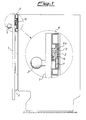
- Figs.1 and 2 schematically illustrate a built-in appliance, typically a dishwasher, covered on the front by a decorative panel 1 coupled through mounting members, described hereafter, which engage corresponding seats formed in the door 2.
- a decorative panel 1 coupled through mounting members, described hereafter, which engage corresponding seats formed in the door 2.
- an easy and balanced sliding of panel 1 is assured by four points of coupling to door 2, both at the top and at the bottom and along both the right and left side. Therefore, the following description concerning the mounting members on the right (looking frontally at the panel) can be applied specularly also to the members on the left.
- panel 1 The passage of panel 1 from the upper position of fig. 1 to the lower position of fig.2 is controlled through the handle 3 for the opening of door 2, in the way which will be described later. Once it has been released, panel 1 slides downwards for a short length so as to make accessible the upper portion of the front plate 4 where the cycle display and the control switchboard, possibly of the push-pull type, are located. It should be noted that the travel of panel 1 may be either the shortest travel required for the access to the controls and such as to allow the opening of door 2 even with panel 1 in the lower position, or a longer travel to make visible a higher portion of the front plate 4.
- the device allowing the vertical sliding of panel 1 between said two positions consists of a support plate 5 on which a substantially T-shaped rod 6 is pivoted, whose free end 6a moves within a track formed in a guide plate 7.
- the support plate 5 is secured on the rear side of panel 1, while the guide plate 7 is embedded into a corresponding seat 8 formed in the upper portion of door 2.
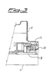
- This seat 8 as clearly shown in figs.1 and 2, has such a depth as to receive the whole sliding device so that panel 1 is mounted on door 2 with a very small play but sufficient for sliding panel 1 vertically. In this way, the free end 6a of rod 6 always remains engaged in the track of the guide plate 7.
- peg 9 having an ogive-shaped tip extending rearwardly into a cylindrical body whose cross-section is reduced by a recess along a plane parallel to a vertical mid-plane, thus forming a vertical tooth on the rear of the tip.
- peg 9 is introduced into a seat formed in door 2 with a vertically elongated rectangular shape. The height of said seat, together with the sliding device to be described further on, defines the sliding travel of panel 1 on door 2 (which may be indicatively of 15-20 mm to 40-50 mm).
- the coupling of peg 9 takes place through the axial sliding of bolt 10 in its own seat against the action of a spring 11, which prevents the subsequent uncoupling only made possible by using a specific tool.
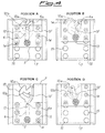
- the guide plate 7 has an asymmetrical track 12 whose shape reminds a heart.
- This track is a bilateral restraint since it is made up of an outer perimeter 12a and an inner perimeter 12b.
- the outer perimeter 12a has a first "stop” 13 at the tip of the "heart”
- the inner perimeter 12b has a similar "stop” 13' formed on the right edge of its upper side.
- the support plate 5 is secured on panel 1 through six screws housed in suitable bores 14.
- the guide plate 7 has the same number of holes 15 to allow the fixing of the support plate 5 when holes 14 and 15 are aligned (position C). In this way, the sliding device can be assembled completely on panel 1 and then it can be coupled to door 2 by simply introducing frontally the guide plate 7 and pegs 9 into their respective seats.
- the movement to take back panel 1 to the upper position is opposite and substantially similar to the above-described movement for the lowering thereof.
- Panel 1 is raised so that the end 6a slides leftwards along the overlying inclined plane which makes part of the inner perimeter 12b, and then rightwards along the outer perimeter 12a, until it abuts at the top of the guide plate 7 (position D). Form this position, panel 1 can move down and slide rightwards along the upper inclined plane of the inner perimeter 12b until it is back to the upper stop 13' (position A).
Landscapes
- Casings For Electric Apparatus (AREA)
- Wing Frames And Configurations (AREA)
- Specific Sealing Or Ventilating Devices For Doors And Windows (AREA)
- Securing Of Glass Panes Or The Like (AREA)
- Washing And Drying Of Tableware (AREA)
Applications Claiming Priority (2)
| Application Number | Priority Date | Filing Date | Title |
|---|---|---|---|
| IT96MI001481A IT1283441B1 (it) | 1996-07-17 | 1996-07-17 | Pannello decorativo dotato di dispositivo per lo scorrimento verticale lungo lo sportello chiuso di un elettrodomestico da |
| ITMI961481 | 1996-07-17 |
Publications (3)
| Publication Number | Publication Date |
|---|---|
| EP0819404A2 true EP0819404A2 (de) | 1998-01-21 |
| EP0819404A3 EP0819404A3 (de) | 1998-05-27 |
| EP0819404B1 EP0819404B1 (de) | 2003-02-05 |
Family
ID=11374603
Family Applications (1)
| Application Number | Title | Priority Date | Filing Date |
|---|---|---|---|
| EP97830352A Expired - Lifetime EP0819404B1 (de) | 1996-07-17 | 1997-07-15 | Dekorplatte mit Vorrichtung zum senkrechten Verschieben längs der geschlossenen Tür eines eingebauten Gerätes |
Country Status (4)
| Country | Link |
|---|---|
| EP (1) | EP0819404B1 (de) |
| DE (1) | DE69718853T2 (de) |
| ES (1) | ES2189938T3 (de) |
| IT (1) | IT1283441B1 (de) |
Cited By (11)
| Publication number | Priority date | Publication date | Assignee | Title |
|---|---|---|---|---|
| EP0873715B1 (de) * | 1997-04-22 | 2002-08-07 | SMEG S.p.A. | Haushaltgerät mit Vorrichtung zum senkrechten Verschieben einer auf die Tür aufgebrachten Dekorplatte |
| EP1366703A1 (de) * | 2002-05-30 | 2003-12-03 | Bonferraro S.p.A. | Einbauhaushaltsgerät mit einer an der Gerätetür befestigten dekorativen Platte |
| EP1374753A1 (de) * | 2002-06-20 | 2004-01-02 | Bonferraro S.p.A. | Haushaltgerät mit einer auf der Tür aufgebrachten Dekorplatte |
| US9387912B2 (en) | 2009-10-09 | 2016-07-12 | Driessen Aircraft Interior Systems, Inc. | Panel inserts for aircraft and other vessels |
| US9387932B2 (en) | 2009-10-09 | 2016-07-12 | Driessen Aircraft Interior Systems, Inc. | Panel inserts for aircraft and other vessels |
| CN107411688A (zh) * | 2017-09-20 | 2017-12-01 | 佛山市顺德区美的洗涤电器制造有限公司 | 连接结构以及洗碗机 |
| US20190000295A1 (en) * | 2017-06-29 | 2019-01-03 | Whirlpool Corporation | Dishwasher door with movable decorative cover |
| US11026558B2 (en) * | 2018-11-15 | 2021-06-08 | Samsung Electronics Co., Ltd. | Home appliance |
| EP3881747A1 (de) * | 2020-03-16 | 2021-09-22 | Miele & Cie. KG | Haushaltsgerät |
| CN116133570A (zh) * | 2020-07-17 | 2023-05-16 | 伊莱克斯电器股份公司 | 具有盖装置的洗碗机 |
| US11950742B2 (en) | 2017-09-20 | 2024-04-09 | Foshan Shunde Midea Washing Appliances Manufacturing Co., Ltd. | Dishwasher water channel, base for dishwasher, and dishwasher |
Family Cites Families (1)
| Publication number | Priority date | Publication date | Assignee | Title |
|---|---|---|---|---|
| DE7915133U1 (de) * | 1979-05-25 | 1980-04-30 | Bosch-Siemens Hausgeraete Gmbh, 7000 Stuttgart | Haushaltgerät mit einer schwenkbaren Tür und einer Vorsatzplatte |
-
1996
- 1996-07-17 IT IT96MI001481A patent/IT1283441B1/it active IP Right Grant
-
1997
- 1997-07-15 EP EP97830352A patent/EP0819404B1/de not_active Expired - Lifetime
- 1997-07-15 ES ES97830352T patent/ES2189938T3/es not_active Expired - Lifetime
- 1997-07-15 DE DE69718853T patent/DE69718853T2/de not_active Expired - Fee Related
Cited By (16)
| Publication number | Priority date | Publication date | Assignee | Title |
|---|---|---|---|---|
| EP0873715B1 (de) * | 1997-04-22 | 2002-08-07 | SMEG S.p.A. | Haushaltgerät mit Vorrichtung zum senkrechten Verschieben einer auf die Tür aufgebrachten Dekorplatte |
| EP1366703A1 (de) * | 2002-05-30 | 2003-12-03 | Bonferraro S.p.A. | Einbauhaushaltsgerät mit einer an der Gerätetür befestigten dekorativen Platte |
| EP1374753A1 (de) * | 2002-06-20 | 2004-01-02 | Bonferraro S.p.A. | Haushaltgerät mit einer auf der Tür aufgebrachten Dekorplatte |
| US9387912B2 (en) | 2009-10-09 | 2016-07-12 | Driessen Aircraft Interior Systems, Inc. | Panel inserts for aircraft and other vessels |
| US9387932B2 (en) | 2009-10-09 | 2016-07-12 | Driessen Aircraft Interior Systems, Inc. | Panel inserts for aircraft and other vessels |
| US20190000295A1 (en) * | 2017-06-29 | 2019-01-03 | Whirlpool Corporation | Dishwasher door with movable decorative cover |
| US10390681B2 (en) * | 2017-06-29 | 2019-08-27 | Whirlpool Corporation | Dishwasher door with movable decorative cover |
| CN107411688B (zh) * | 2017-09-20 | 2023-05-26 | 佛山市顺德区美的洗涤电器制造有限公司 | 连接结构以及洗碗机 |
| CN107411688A (zh) * | 2017-09-20 | 2017-12-01 | 佛山市顺德区美的洗涤电器制造有限公司 | 连接结构以及洗碗机 |
| US12207779B2 (en) | 2017-09-20 | 2025-01-28 | Foshan Shunde Midea Washing Appliances Manufacturing Co., Ltd. | Connection structure and dishwasher |
| US11950742B2 (en) | 2017-09-20 | 2024-04-09 | Foshan Shunde Midea Washing Appliances Manufacturing Co., Ltd. | Dishwasher water channel, base for dishwasher, and dishwasher |
| US11026558B2 (en) * | 2018-11-15 | 2021-06-08 | Samsung Electronics Co., Ltd. | Home appliance |
| EP3881747A1 (de) * | 2020-03-16 | 2021-09-22 | Miele & Cie. KG | Haushaltsgerät |
| US20230270314A1 (en) * | 2020-07-17 | 2023-08-31 | Electrolux Appliances Aktiebolag | Dishwasher with cover device |
| CN116133570A (zh) * | 2020-07-17 | 2023-05-16 | 伊莱克斯电器股份公司 | 具有盖装置的洗碗机 |
| US12390082B2 (en) * | 2020-07-17 | 2025-08-19 | Electrolux Appliances Aktiebolag | Dishwasher with cover device |
Also Published As
| Publication number | Publication date |
|---|---|
| ES2189938T3 (es) | 2003-07-16 |
| ITMI961481A0 (de) | 1996-07-17 |
| ITMI961481A1 (it) | 1998-01-17 |
| DE69718853T2 (de) | 2003-11-13 |
| EP0819404B1 (de) | 2003-02-05 |
| EP0819404A3 (de) | 1998-05-27 |
| DE69718853D1 (de) | 2003-03-13 |
| IT1283441B1 (it) | 1998-04-21 |
Similar Documents
| Publication | Publication Date | Title |
|---|---|---|
| EP0819404B1 (de) | Dekorplatte mit Vorrichtung zum senkrechten Verschieben längs der geschlossenen Tür eines eingebauten Gerätes | |
| US4900109A (en) | Versatile dishwasher front construction | |
| CA1160149A (en) | Mechanism for a roller blind | |
| EP1529482B1 (de) | Eingebautes Haushaltsgerät mit an die Tür angebrachter dekorativer Vorsatzplatte | |
| EP0744152B1 (de) | Vorrichtung für die gleitende Montage einer dekorativen Platte auf die Tür eines eingebauten Haushaltgerätes | |
| US5938306A (en) | Cabinet and door assembly | |
| EP3025619A1 (de) | Verankerungsgruppe für wandschränke mit regelung von oben | |
| EP1894509A1 (de) | Haushaltseinbaugerät mit an die Gerätetür angeordneter Vorsatzplatte | |
| DE19922647A1 (de) | Haushaltsgerät zum Einsetzen in eine Möbelzelle und Element einer Möbelzeile | |
| US5800029A (en) | Combination work and storage cabinets | |
| EP0873715B1 (de) | Haushaltgerät mit Vorrichtung zum senkrechten Verschieben einer auf die Tür aufgebrachten Dekorplatte | |
| EP0575300A1 (de) | Vorrichtung für Geschirrspülertüre | |
| GB2079589A (en) | A door for domestic electrical appliances | |
| EP0917853B1 (de) | Türschliessvorrichtung für ein Haushaltsgerät, beispielsweise eine Geschirrspülmaschine | |
| DE102020105158B4 (de) | System, umfassend eine Möbeltüreinheit und ein in eine Einbaunische einer Möbelumgebung einbaubares Haushaltsgerät | |
| DE10063353A1 (de) | Tür für Haushaltgeräte | |
| DE2937455C2 (de) | Haushaltgerät, insbesondere Geschirrspülmaschine, mit einer Tür und einer Vorsatzplatte | |
| EP1502536B1 (de) | Eingebautes Haushaltsgerät mit vorderen Schönheitspaneelen | |
| EP1702550B1 (de) | Bewegungsvorrichtung für ein Einbaugerät oder dergleichen, mit Einklemmschutz | |
| EP1998117B1 (de) | BACKOFEN MIT EINER SCHLIEßVORRICHTUNG | |
| EP1366703B1 (de) | Einbauhaushaltsgerät mit einer an der Gerätetür befestigten dekorativen Platte | |
| DE2937447C2 (de) | Anordnung einer Vorsatzplatte an einem Haushaltsgerät, insbesondere einer Geschirrspülmaschine | |
| JP2000210242A (ja) | 食器洗い機 | |
| EP1380250A1 (de) | Einbauhaushaltgerät mit einer frontseitigen Dekorplatte | |
| EP1591040A1 (de) | Einbau-Haushaltsgerät mit dekorativer Frontplatte |
Legal Events
| Date | Code | Title | Description |
|---|---|---|---|
| PUAI | Public reference made under article 153(3) epc to a published international application that has entered the european phase |
Free format text: ORIGINAL CODE: 0009012 |
|
| AK | Designated contracting states |
Kind code of ref document: A2 Designated state(s): DE ES FR GB SE |
|
| AX | Request for extension of the european patent |
Free format text: AL;LT;LV;RO;SI |
|
| PUAL | Search report despatched |
Free format text: ORIGINAL CODE: 0009013 |
|
| AK | Designated contracting states |
Kind code of ref document: A3 Designated state(s): AT BE CH DE DK ES FI FR GB GR IE IT LI LU MC NL PT SE |
|
| AX | Request for extension of the european patent |
Free format text: AL;LT;LV;RO;SI |
|
| 17P | Request for examination filed |
Effective date: 19980925 |
|
| 17Q | First examination report despatched |
Effective date: 19981119 |
|
| AKX | Designation fees paid |
Free format text: DE ES FR GB SE |
|
| RBV | Designated contracting states (corrected) |
Designated state(s): DE ES FR GB SE |
|
| GRAH | Despatch of communication of intention to grant a patent |
Free format text: ORIGINAL CODE: EPIDOS IGRA |
|
| GRAH | Despatch of communication of intention to grant a patent |
Free format text: ORIGINAL CODE: EPIDOS IGRA |
|
| GRAA | (expected) grant |
Free format text: ORIGINAL CODE: 0009210 |
|
| AK | Designated contracting states |
Designated state(s): DE ES FR GB SE |
|
| REG | Reference to a national code |
Ref country code: GB Ref legal event code: FG4D |
|
| REF | Corresponds to: |
Ref document number: 69718853 Country of ref document: DE Date of ref document: 20030313 Kind code of ref document: P |
|
| REG | Reference to a national code |
Ref country code: SE Ref legal event code: TRGR |
|
| REG | Reference to a national code |
Ref country code: ES Ref legal event code: FG2A Ref document number: 2189938 Country of ref document: ES Kind code of ref document: T3 |
|
| ET | Fr: translation filed | ||
| PLBE | No opposition filed within time limit |
Free format text: ORIGINAL CODE: 0009261 |
|
| STAA | Information on the status of an ep patent application or granted ep patent |
Free format text: STATUS: NO OPPOSITION FILED WITHIN TIME LIMIT |
|
| 26N | No opposition filed |
Effective date: 20031106 |
|
| PGFP | Annual fee paid to national office [announced via postgrant information from national office to epo] |
Ref country code: GB Payment date: 20040630 Year of fee payment: 8 |
|
| PGFP | Annual fee paid to national office [announced via postgrant information from national office to epo] |
Ref country code: SE Payment date: 20040705 Year of fee payment: 8 |
|
| PGFP | Annual fee paid to national office [announced via postgrant information from national office to epo] |
Ref country code: DE Payment date: 20040706 Year of fee payment: 8 |
|
| PGFP | Annual fee paid to national office [announced via postgrant information from national office to epo] |
Ref country code: FR Payment date: 20040708 Year of fee payment: 8 |
|
| PGFP | Annual fee paid to national office [announced via postgrant information from national office to epo] |
Ref country code: ES Payment date: 20040716 Year of fee payment: 8 |
|
| PG25 | Lapsed in a contracting state [announced via postgrant information from national office to epo] |
Ref country code: GB Free format text: LAPSE BECAUSE OF NON-PAYMENT OF DUE FEES Effective date: 20050715 |
|
| PG25 | Lapsed in a contracting state [announced via postgrant information from national office to epo] |
Ref country code: SE Free format text: LAPSE BECAUSE OF NON-PAYMENT OF DUE FEES Effective date: 20050716 Ref country code: ES Free format text: LAPSE BECAUSE OF NON-PAYMENT OF DUE FEES Effective date: 20050716 |
|
| PG25 | Lapsed in a contracting state [announced via postgrant information from national office to epo] |
Ref country code: DE Free format text: LAPSE BECAUSE OF NON-PAYMENT OF DUE FEES Effective date: 20060201 |
|
| EUG | Se: european patent has lapsed | ||
| GBPC | Gb: european patent ceased through non-payment of renewal fee |
Effective date: 20050715 |
|
| PG25 | Lapsed in a contracting state [announced via postgrant information from national office to epo] |
Ref country code: FR Free format text: LAPSE BECAUSE OF NON-PAYMENT OF DUE FEES Effective date: 20060331 |
|
| REG | Reference to a national code |
Ref country code: FR Ref legal event code: ST Effective date: 20060331 |
|
| REG | Reference to a national code |
Ref country code: ES Ref legal event code: FD2A Effective date: 20050716 |