EP0819444A2 - Mehrwegeschalteinrichtung für Durchflussmengen - Google Patents
Mehrwegeschalteinrichtung für Durchflussmengen Download PDFInfo
- Publication number
- EP0819444A2 EP0819444A2 EP97112027A EP97112027A EP0819444A2 EP 0819444 A2 EP0819444 A2 EP 0819444A2 EP 97112027 A EP97112027 A EP 97112027A EP 97112027 A EP97112027 A EP 97112027A EP 0819444 A2 EP0819444 A2 EP 0819444A2
- Authority
- EP
- European Patent Office
- Prior art keywords
- flow rate
- liquid medicine
- path
- flow
- switching device
- Prior art date
- Legal status (The legal status is an assumption and is not a legal conclusion. Google has not performed a legal analysis and makes no representation as to the accuracy of the status listed.)
- Granted
Links
Images


Classifications
-
- A—HUMAN NECESSITIES
- A61—MEDICAL OR VETERINARY SCIENCE; HYGIENE
- A61M—DEVICES FOR INTRODUCING MEDIA INTO, OR ONTO, THE BODY; DEVICES FOR TRANSDUCING BODY MEDIA OR FOR TAKING MEDIA FROM THE BODY; DEVICES FOR PRODUCING OR ENDING SLEEP OR STUPOR
- A61M5/00—Devices for bringing media into the body in a subcutaneous, intra-vascular or intramuscular way; Accessories therefor, e.g. filling or cleaning devices, arm-rests
- A61M5/14—Infusion devices, e.g. infusing by gravity; Blood infusion; Accessories therefor
- A61M5/141—Infusion devices, e.g. infusing by gravity; Blood infusion; Accessories therefor with capillaries for restricting fluid flow
-
- A—HUMAN NECESSITIES
- A61—MEDICAL OR VETERINARY SCIENCE; HYGIENE
- A61M—DEVICES FOR INTRODUCING MEDIA INTO, OR ONTO, THE BODY; DEVICES FOR TRANSDUCING BODY MEDIA OR FOR TAKING MEDIA FROM THE BODY; DEVICES FOR PRODUCING OR ENDING SLEEP OR STUPOR
- A61M5/00—Devices for bringing media into the body in a subcutaneous, intra-vascular or intramuscular way; Accessories therefor, e.g. filling or cleaning devices, arm-rests
- A61M5/14—Infusion devices, e.g. infusing by gravity; Blood infusion; Accessories therefor
- A61M5/168—Means for controlling media flow to the body or for metering media to the body, e.g. drip meters, counters ; Monitoring media flow to the body
- A61M5/16877—Adjusting flow; Devices for setting a flow rate
-
- Y—GENERAL TAGGING OF NEW TECHNOLOGICAL DEVELOPMENTS; GENERAL TAGGING OF CROSS-SECTIONAL TECHNOLOGIES SPANNING OVER SEVERAL SECTIONS OF THE IPC; TECHNICAL SUBJECTS COVERED BY FORMER USPC CROSS-REFERENCE ART COLLECTIONS [XRACs] AND DIGESTS
- Y10—TECHNICAL SUBJECTS COVERED BY FORMER USPC
- Y10T—TECHNICAL SUBJECTS COVERED BY FORMER US CLASSIFICATION
- Y10T137/00—Fluid handling
- Y10T137/8593—Systems
- Y10T137/87265—Dividing into parallel flow paths with recombining
- Y10T137/87338—Flow passage with bypass
-
- Y—GENERAL TAGGING OF NEW TECHNOLOGICAL DEVELOPMENTS; GENERAL TAGGING OF CROSS-SECTIONAL TECHNOLOGIES SPANNING OVER SEVERAL SECTIONS OF THE IPC; TECHNICAL SUBJECTS COVERED BY FORMER USPC CROSS-REFERENCE ART COLLECTIONS [XRACs] AND DIGESTS
- Y10—TECHNICAL SUBJECTS COVERED BY FORMER USPC
- Y10T—TECHNICAL SUBJECTS COVERED BY FORMER US CLASSIFICATION
- Y10T137/00—Fluid handling
- Y10T137/8593—Systems
- Y10T137/87265—Dividing into parallel flow paths with recombining
- Y10T137/87523—Rotary valve
Definitions
- the present invention relates to a flow rate switching device capable of switching a liquid flow rate in multi stages.
- the present invention relates to a multi-stage type flow rate switching device capable of switching the flow rate of a liquid medicine in several stages by using a three-way stopcock.
- the multi-stage type flow rate switching device according to the present invention is preferably used by being connected to a ballooned liquid medicine continuous injector (an injector where liquid medicine is filled in a balloon made of an elastic rubber material and liquid medicine is continuously injected over a period of many hours into blood vessels or the like by utilizing the force produced by contraction of the balloon as disclosed in, for example, Japanese Examined Patent Publication No. JP-B-6-83725) that is used as a means for continuously administering a liquid analgetic, anesthetic, antibiotic, or carcinostatic agent into blood vessels, hypodermic portions, epidural portions or the like in a small amount.
- a ballooned liquid medicine continuous injector an injector where liquid medicine is filled in a balloon made of an elastic rubber material and liquid medicine is continuously injected over a period of many hours into blood vessels or the like by
- a three-way stopcock has conventionally been used in the medical field when a blood transfusion or a solution transfusion is carried out.
- a three-way stopcock is typically constituted by a cylindrical portion having three branch tubes projecting in a T-like shape at the outer periphery of the cylindrical portion, a plug portion inserted in and rotatably attached to the cylindrical portion and having a liquid path in a T-like shape corresponding to the branch tubes of the cylindrical portion, and a lever attached to the plug portion for switching the flow paths.
- a device comprising flow rate control tubes connected to a multi-way stopcock
- the device is constituted by a main body having a cylindrical valve chamber where one flow inlet port and at least three flow outlet ports are formed.
- a plug having a cylindrical valve portion is rotatably inserted into the valve chamber of the main body.
- the present invention has been achieved as a result of an intensive study in view of the above-described situation and it is an object of the present invention to provide a multi stage type flow rate switching device which simplifies switching of flow paths and rarely causes erroneous operation.
- the inventors have determined as a result of an intensive study, that flow rate switching operations can be facilitated and erroneous operation can be prevented by assembling a constant flow rate path and a variable flow rate path inparallel between a liquid medicine flow inlet port and a liquid medicine flow outlet port of a flow rate switching device and appropriately providing a three-way stopcock in the variable flow rate path.
- the present invention is directed to a multi-stage type flow rate switching device that includes a constant flow rate path and at least one variable flow rate path arranged in parallel between a liquid medicine flow inlet port and a liquid medicine flow outlet port where the flow rate of the variable flow rate path can be varied by a three-way stopcock.
- the multi stage type flow rate switching device may have the following construction.
- the liquid medicine flow inlet port is branched into three branch paths. One of the branch paths and the two remaining branch paths are respectively connected to the constant flow rate path and the variable flow rate path.
- Flow rate control tubes for controlling flow rate by resistance to flow are arranged in the constant flow rate path and the variable flow rate path between the liquid medicine flow inlet port and the three-way stopcock.
- the liquid medicine flow outlet port is branched into three branch paths.
- One of the branch paths and the two remaining branch paths are respectively connected to a constant flow rate path and a variable flow rate path.
- Flow rate control tubes for controlling the flow rate by resistance to flow may be arranged in the constant flow rate path and the variable flow rate path which is arranged between the liquid medicine flow outlet port and a three-way stopcock.
- the constant flow rate path and the variable flow rate path may preferably be accommodated in a housing having a liquid medicine flow inlet port and a liquid medicine flow outlet port at both ends thereof.
- a multi-stage flow rate switching device of the present invention includes a constant flow rate path 2 and a variable flow rate path 3.
- the paths are arranged in parallel between a liquid medicine flow inlet port 1 and a liquid medicine flow outlet port 4 and the flow rate of the variable flow rate path 3 can be changed by a three-way stopcock 33.
- the flow rate can be switched in four stages when one variable flow rate path 3 is arranged as shown by Fig. 1, the flow rate can be switched in further multi stages by providing two or more of the variable flow rate paths 3 as necessary.
- the liquid medicine flow inlet port 1 is branched into three branch paths 11, 12 and 13 and the liquid medicine flow outlet port 4 is branched into two branch paths 41 and 42.
- the constant flow rate path 2 is connected between the first branch path 11 of the liquid medicine flow inlet port 1 and the first branch path 41 of the liquid medicine flow outlet port 4.
- the variable flow rate path 3 is connected between the second branch path 12 and the third branch path 13 of the liquid medicine flow inlet port 1 and the second branch path 42 of the liquid medicine flow outlet port 4.
- the constant flow rate path 2 includes a flow rate control tube for controlling the flow rate by flow resistance.
- the entirety of the constant flow rate path 2 may be constituted by a flow rate control tube.
- variable flow rate path 3 is constituted by the three-way stopcock 33, flow rate control tubes 31 and 32 respectively connected to the second branch path 12 and the third branch path 13 of the liquid medicine flow inlet port 1 and the three-way stopcock 33, and a connection tube 34 connected to the three-way stop cock 33 and the second branch path 42 of the liquid medicine flow outlet port 4 such that the flow rate can be varied by the three-way stopcock 33.
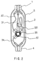
- the multi-stage type flow rate switching device may be constituted such that the liquid medicine flow inlet port 1 and the liquid medicine flow outlet port 4 are completely reversed in Fig. 1. That is, liquid medicine flows from the side of the liquid medicine flow outlet port 4 to the side of the liquid medicine flow inlet port 1 shown in Fig. 1. Also, the multi-stage type flow rate switching device may be constituted such that the device is accommodated in a housing 5 having a hole 51 for exposing a lever 331 of the three-way stopcock 33 as shown in Fig. 2.
- variable flow rate paths 3 may be assembled in parallel between a liquid medicine flow inlet port 1 and a liquid medicine flow outlet port 4 in the multi-stage type flow rate switching device.
- the flow rate can be switched in four stages when one variable flow rate path 3 is provided, the flow rate can be switched in sixteen stages when two of the variable flow rate paths 3 are provided.
- the flow rates of the constant flow rate path 2 and the flow rate control tubes 31 and 32 of the variable flow rate path 3 in Fig.1 are respectively set to, for example, 1 ml/hr, 1 ml/hr and 2 ml/hr
- the flow rates can be set to four stages of 1 ml/hr, 2 ml/hr, 3 ml/hr and 4 ml/hr.
- the flow rates can be set in sixteen stages of 1 ml/hr through 16 ml/hr by setting the flow rates of the second variable flow rate path of the two flow rate control tubes respectively to 4 ml/hr and 8 ml/hr.
- the multi-stage type flow rate switching device of the present invention is mainly used by being combined with a liquid transfusion line as shown in Fig. 3.
- notation E designates the multi-stage type flow rate switching device
- notation C designates a clamp
- numerals 6 and 7 designate connection tubes
- numerals 8 and 9 designate connectors.
- the connector 8 on the upstream side is connected to a liquid medicine injecting device, not shown, which utilizes the elastic force of a balloon, and the connector 9 on the downstream side is connected to a retaining needle, not shown.
- the clamp C is initially closed. When the clamp C is detached after setting the flow rate by operating the lever 331, a liquid medicine can be injected into blood vessels of a patient.
Landscapes
- Health & Medical Sciences (AREA)
- Biomedical Technology (AREA)
- Hematology (AREA)
- Vascular Medicine (AREA)
- Engineering & Computer Science (AREA)
- Anesthesiology (AREA)
- Physics & Mathematics (AREA)
- Heart & Thoracic Surgery (AREA)
- Fluid Mechanics (AREA)
- Life Sciences & Earth Sciences (AREA)
- Animal Behavior & Ethology (AREA)
- General Health & Medical Sciences (AREA)
- Public Health (AREA)
- Veterinary Medicine (AREA)
- Infusion, Injection, And Reservoir Apparatuses (AREA)
Applications Claiming Priority (3)
| Application Number | Priority Date | Filing Date | Title |
|---|---|---|---|
| JP187682/96 | 1996-07-17 | ||
| JP18768296 | 1996-07-17 | ||
| JP18768296A JP3266901B2 (ja) | 1996-07-17 | 1996-07-17 | 多段式流量切換装置 |
Publications (3)
| Publication Number | Publication Date |
|---|---|
| EP0819444A2 true EP0819444A2 (de) | 1998-01-21 |
| EP0819444A3 EP0819444A3 (de) | 1998-04-29 |
| EP0819444B1 EP0819444B1 (de) | 2001-09-19 |
Family
ID=16210304
Family Applications (1)
| Application Number | Title | Priority Date | Filing Date |
|---|---|---|---|
| EP97112027A Expired - Lifetime EP0819444B1 (de) | 1996-07-17 | 1997-07-15 | Mehrwegeschalteinrichtung für Durchflussmengen |
Country Status (4)
| Country | Link |
|---|---|
| US (1) | US5927326A (de) |
| EP (1) | EP0819444B1 (de) |
| JP (1) | JP3266901B2 (de) |
| DE (1) | DE69706778T2 (de) |
Families Citing this family (11)
| Publication number | Priority date | Publication date | Assignee | Title |
|---|---|---|---|---|
| JP4010005B2 (ja) | 2000-02-29 | 2007-11-21 | ニプロ株式会社 | 薬液注入器の注入速度調整装置 |
| ES2173042B1 (es) * | 2001-02-28 | 2003-06-16 | Lucas Victor Grifols | Dispositivo y procedimiento para el control de caudal para productos medicamentosos. |
| WO2007024798A2 (en) * | 2005-08-22 | 2007-03-01 | Applera Corporation | Apparatus, system, and method using immiscible-fluid-discrete-volumes |
| JP4765721B2 (ja) * | 2006-03-30 | 2011-09-07 | 住友金属工業株式会社 | 鉄道車両用空気ばねの高さ調整装置 |
| US7690396B2 (en) * | 2006-07-20 | 2010-04-06 | Baxter International Inc. | Multirate tubing flow restrictor |
| JP2007330800A (ja) * | 2007-07-20 | 2007-12-27 | Nipro Corp | 薬液注入器の注入速度調整装置 |
| US8919425B2 (en) * | 2008-09-02 | 2014-12-30 | Halla Visteon Climate Control Corporation | Flow control valve and heat exchanger equipped with same |
| US20120259291A1 (en) * | 2011-04-06 | 2012-10-11 | Navilyst Medical, Inc. | Medical flow device for multi-lumen catheters |
| AU2014214890A1 (en) * | 2013-02-11 | 2015-08-20 | California Institute Of Technology | Multi-path multi-stage erosion-resistant valve for downhole flow control |
| EP2956190A4 (de) * | 2013-02-15 | 2016-08-24 | Repro Med Systems Inc | Universeller mehrfachströmungs-tubussatz |
| US9258949B2 (en) | 2013-06-19 | 2016-02-16 | National Diversified Sales, Inc. | Adjustable drip emitter |
Family Cites Families (11)
| Publication number | Priority date | Publication date | Assignee | Title |
|---|---|---|---|---|
| US2509456A (en) * | 1949-03-19 | 1950-05-30 | Powers Regulator Co | Automatic restriction valve |
| US3010316A (en) * | 1957-12-16 | 1961-11-28 | Anning Johnson Company | Fluid flow regulating and indicating apparatus |
| US3298367A (en) * | 1964-01-10 | 1967-01-17 | Richard I Bergman | Apparatus for administering parenteral liquids |
| US3788602A (en) * | 1972-07-19 | 1974-01-29 | Becton Dickinson Co | Stopcock |
| US4276904A (en) * | 1976-09-01 | 1981-07-07 | The United States Of America As Represented By The United States Department Of Energy | Adjustable flow rate controller for polymer solutions |
| US4219021A (en) * | 1978-02-27 | 1980-08-26 | Fink Joseph L | Multi-position stop-cock valve for intravenous administration of multiple medications |
| US4237879A (en) | 1979-02-28 | 1980-12-09 | Abbott Laboratories | Equipment sets for the sequential administration of medical liquids at dual flow rates employing parallel secondary liquid tubing and a 3-way valve |
| US4573974A (en) * | 1982-12-01 | 1986-03-04 | Baxter Travenol Laboratories, Inc. | Medical administration set enabling sequential delivery of two liquids at different flow rate |
| US4643224A (en) * | 1985-09-04 | 1987-02-17 | Victaulic Company Of America | Alarm test device for a sprinkler system |
| US5356379A (en) * | 1993-08-03 | 1994-10-18 | Vaillancourt Vincent L | Disposable ambulatory infusion pump assembly |
| JP3203636B2 (ja) * | 1996-04-10 | 2001-08-27 | ニプロ株式会社 | 流量制御装置 |
-
1996
- 1996-07-17 JP JP18768296A patent/JP3266901B2/ja not_active Expired - Fee Related
-
1997
- 1997-07-14 US US08/892,159 patent/US5927326A/en not_active Expired - Lifetime
- 1997-07-15 EP EP97112027A patent/EP0819444B1/de not_active Expired - Lifetime
- 1997-07-15 DE DE69706778T patent/DE69706778T2/de not_active Expired - Lifetime
Also Published As
| Publication number | Publication date |
|---|---|
| DE69706778T2 (de) | 2002-07-04 |
| JPH1028741A (ja) | 1998-02-03 |
| EP0819444A3 (de) | 1998-04-29 |
| EP0819444B1 (de) | 2001-09-19 |
| DE69706778D1 (de) | 2001-10-25 |
| JP3266901B2 (ja) | 2002-03-18 |
| US5927326A (en) | 1999-07-27 |
Similar Documents
| Publication | Publication Date | Title |
|---|---|---|
| US5839470A (en) | Three-way stopcock and flow rate control device in use thereof | |
| EP0805694B1 (de) | Anti-cross-kontaminationsventil und seine verwendung in einem flüssigkeitsverabreichungssystem | |
| US5927326A (en) | Multi stage type flow rate switching device | |
| US6158467A (en) | Four-port, four-way, stopcock for intravenous injections and infusions and direction of flow of fluids and gasses | |
| US4451255A (en) | Dual flow rate intravenous administration set with single pump chamber | |
| US7172572B2 (en) | Manifold system for a medical device | |
| US7695445B2 (en) | Three-way stopcock, and liquid transfusion circuit or blood transfusion circuit either using the three-way stopcock | |
| EP0836859B1 (de) | Mehrstufige Vorrichtung zur Durchflussmengenänderung | |
| JP2007236964A (ja) | 流体流速切替え装置 | |
| WO1993001859A1 (en) | Multi-valve manifold for drug infusion systems | |
| KR20160029411A (ko) | 주입량 및 주입방향 조절형 밸브 | |
| US4738265A (en) | Dual stop cock | |
| JPH09225028A (ja) | 薬液の流量切換器 | |
| JP3398058B2 (ja) | 薬液の流量調整装置、およびそれを備えた薬液注入装置 | |
| EP0405907A1 (de) | Einrichtung zur intravaskulären Infusion | |
| JPH0626584B2 (ja) | 分岐バルブ | |
| JPH10179735A (ja) | 薬液注入器具 | |
| GB2233563A (en) | Multiple interconnection apparatus for infusion lines | |
| JP2003190280A (ja) | 脳内血管治療用液体灌流システム | |
| JP2001190664A (ja) | 薬液持続注入器用送液チューブ | |
| HK1004377A1 (en) | Apparatus for controlling flow of biological/medical fluids to and from a patient |
Legal Events
| Date | Code | Title | Description |
|---|---|---|---|
| PUAI | Public reference made under article 153(3) epc to a published international application that has entered the european phase |
Free format text: ORIGINAL CODE: 0009012 |
|
| AK | Designated contracting states |
Kind code of ref document: A2 Designated state(s): BE DE FR GB IT |
|
| PUAL | Search report despatched |
Free format text: ORIGINAL CODE: 0009013 |
|
| AK | Designated contracting states |
Kind code of ref document: A3 Designated state(s): AT BE CH DE DK ES FI FR GB GR IE IT LI LU MC NL PT SE |
|
| RHK1 | Main classification (correction) |
Ipc: A61M 5/14 |
|
| 17P | Request for examination filed |
Effective date: 19980928 |
|
| AKX | Designation fees paid |
Free format text: BE DE FR GB IT |
|
| RBV | Designated contracting states (corrected) |
Designated state(s): BE DE FR GB IT |
|
| 17Q | First examination report despatched |
Effective date: 20000127 |
|
| GRAG | Despatch of communication of intention to grant |
Free format text: ORIGINAL CODE: EPIDOS AGRA |
|
| GRAG | Despatch of communication of intention to grant |
Free format text: ORIGINAL CODE: EPIDOS AGRA |
|
| GRAH | Despatch of communication of intention to grant a patent |
Free format text: ORIGINAL CODE: EPIDOS IGRA |
|
| GRAH | Despatch of communication of intention to grant a patent |
Free format text: ORIGINAL CODE: EPIDOS IGRA |
|
| GRAA | (expected) grant |
Free format text: ORIGINAL CODE: 0009210 |
|
| RAP1 | Party data changed (applicant data changed or rights of an application transferred) |
Owner name: NIPRO CORPORATION |
|
| AK | Designated contracting states |
Kind code of ref document: B1 Designated state(s): BE DE FR GB IT |
|
| ITF | It: translation for a ep patent filed | ||
| REF | Corresponds to: |
Ref document number: 69706778 Country of ref document: DE Date of ref document: 20011025 |
|
| REG | Reference to a national code |
Ref country code: GB Ref legal event code: IF02 |
|
| ET | Fr: translation filed | ||
| PLBE | No opposition filed within time limit |
Free format text: ORIGINAL CODE: 0009261 |
|
| STAA | Information on the status of an ep patent application or granted ep patent |
Free format text: STATUS: NO OPPOSITION FILED WITHIN TIME LIMIT |
|
| 26N | No opposition filed | ||
| REG | Reference to a national code |
Ref country code: FR Ref legal event code: PLFP Year of fee payment: 19 |
|
| REG | Reference to a national code |
Ref country code: FR Ref legal event code: PLFP Year of fee payment: 20 |
|
| PGFP | Annual fee paid to national office [announced via postgrant information from national office to epo] |
Ref country code: IT Payment date: 20160725 Year of fee payment: 20 Ref country code: DE Payment date: 20160722 Year of fee payment: 20 Ref country code: GB Payment date: 20160721 Year of fee payment: 20 |
|
| PGFP | Annual fee paid to national office [announced via postgrant information from national office to epo] |
Ref country code: FR Payment date: 20160721 Year of fee payment: 20 |
|
| PGFP | Annual fee paid to national office [announced via postgrant information from national office to epo] |
Ref country code: BE Payment date: 20160720 Year of fee payment: 20 |
|
| REG | Reference to a national code |
Ref country code: DE Ref legal event code: R071 Ref document number: 69706778 Country of ref document: DE |
|
| REG | Reference to a national code |
Ref country code: GB Ref legal event code: PE20 Expiry date: 20170714 |
|
| PG25 | Lapsed in a contracting state [announced via postgrant information from national office to epo] |
Ref country code: GB Free format text: LAPSE BECAUSE OF EXPIRATION OF PROTECTION Effective date: 20170714 |