EP0819640A2 - Trennvorrichtung für Folienbahnen - Google Patents
Trennvorrichtung für Folienbahnen Download PDFInfo
- Publication number
- EP0819640A2 EP0819640A2 EP97111919A EP97111919A EP0819640A2 EP 0819640 A2 EP0819640 A2 EP 0819640A2 EP 97111919 A EP97111919 A EP 97111919A EP 97111919 A EP97111919 A EP 97111919A EP 0819640 A2 EP0819640 A2 EP 0819640A2
- Authority
- EP
- European Patent Office
- Prior art keywords
- separating member
- bracket
- cutting edge
- supply roll
- web section
- Prior art date
- Legal status (The legal status is an assumption and is not a legal conclusion. Google has not performed a legal analysis and makes no representation as to the accuracy of the status listed.)
- Granted
Links
Images



Classifications
-
- B—PERFORMING OPERATIONS; TRANSPORTING
- B65—CONVEYING; PACKING; STORING; HANDLING THIN OR FILAMENTARY MATERIAL
- B65H—HANDLING THIN OR FILAMENTARY MATERIAL, e.g. SHEETS, WEBS, CABLES
- B65H35/00—Delivering articles from cutting or line-perforating machines; Article or web delivery apparatus incorporating cutting or line-perforating devices, e.g. adhesive tape dispensers
- B65H35/0006—Article or web delivery apparatus incorporating cutting or line-perforating devices
-
- B—PERFORMING OPERATIONS; TRANSPORTING
- B26—HAND CUTTING TOOLS; CUTTING; SEVERING
- B26D—CUTTING; DETAILS COMMON TO MACHINES FOR PERFORATING, PUNCHING, CUTTING-OUT, STAMPING-OUT OR SEVERING
- B26D7/00—Details of apparatus for cutting, cutting-out, stamping-out, punching, perforating, or severing by means other than cutting
- B26D7/22—Safety devices specially adapted for cutting machines
-
- B—PERFORMING OPERATIONS; TRANSPORTING
- B26—HAND CUTTING TOOLS; CUTTING; SEVERING
- B26F—PERFORATING; PUNCHING; CUTTING-OUT; STAMPING-OUT; SEVERING BY MEANS OTHER THAN CUTTING
- B26F3/00—Severing by means other than cutting; Apparatus therefor
- B26F3/002—Precutting and tensioning or breaking
Definitions
- the invention relates to a device for severing a web section from the end of a film web wound up as a supply roll in one Training according to the preamble of claim 1.
- Devices of this type are found as household appliances in private households and for thin foils made of paper like parchment paper, metal like aluminum and plastic like PE application.
- the reel carrier forms a shaft on which the supply reel is placed.
- the shaft axis in the The distance in front of the supply roll and slightly below the shaft axis is one Separator with a downward, toothed cutting edge supported in a stationary manner, around which during an upward movement of a withdrawn path section put the foil around. Grip the web section as you pull then cut the teeth of the separator into the film and cut it along the line of intervention.
- the device is part of a roll holder that can be attached to the wall, for example in the area of kitchen niches.
- the supply roll is in one of one Folding box formed housing housed an exit slot for the film has.
- One edge of the slot forms a guide for the film when pulling off a web section.
- the folding box is included on an outer edge with a separator with toothed Provide cutting edge that takes effect when the withdrawn path section placed over the cutting edge of the separator and the pulling is continued.
- the result of a separation process can be especially when there is a lot to be desired to be cut film is one that is either particularly strong or is particularly soft and resilient, such as the former in strong parchment paper or composite film and the latter for example thin PE films are the case, as they are used as cling films.
- This is primarily due to the fact that for reasons of limitation the risk of injury from the cutting edge of the separator the edge protrudes only slightly compared to a support member and is relatively blunt. Sharp and sufficiently exposed cutting edges However, for the sake of the dangers arising from them, they prohibit themselves considerably to hurt, for example when gripping the web end to Purpose of subtracting a track section.
- the invention is concerned with the problem of a device of the type mentioned Art to create at a minimum risk of injury a safe, precise separation process for all films in the household he brings.
- the invention solves the problem with a device with the Features of claim 1. With regard to essential further refinements reference is made to claims 2 to 28.
- the device according to the invention provides with its shielding of the cutting edge the separator when the device is not in use and its exposure only when carrying out a separation process, that even from a sharp isolating link pose no risk of injury to a user. Because his hands are when pulling the web section and when cutting outside the danger area of the cutting edge of the Isolator. This is experienced immediately after the separation process has been carried out Isolator again automatically a shield, because with the end of the Cutting process the operating process exposing the cutting edge of the cutting member due to the track section.
- the separator can be so sharp in the device according to the invention and project so far above a support that with all usual household foils a perfect separation of web sections is guaranteed even then is when only a relatively small amount of tension is exerted on the web section to be separated becomes.
- Separating device 2 comprises a roller carrier in the embodiment according to FIGS. 1 to 4 3, which is formed by a trough open at the top, in which the supply roll 5 of a household film web is included.
- the roller carrier 3 comprises furthermore an axle rod 7 passing through the winding tube 6 of the supply roll 5, which holds the supply roll 5 in the trough 6 with its weight when on one end 8 of the film web 9 is pulled to separate one Subtract web section 31.
- the axle rod 7 carries radially End disks 10 projecting over the circumference of the supply roll 5 as axial Secure the position of the unit consisting of supply roll 5 and axle rod 7 in the trough 4. At least one of the end disks 10 is detachably fastened, to enable the winding of a supply roll 5.
- the separator further comprises a separator 11, one from the other adjacent cutting teeth 12 has formed edge 13 and on a support rail 14 is attached. That of a thin stainless steel blade
- the separator 11 formed is preferred in the cutting area 15 at least on one side but ground on two sides, so that the separator 11 has a sharp Cutting edge 13 offers.
- the separator 11 is preferably at least full Cutting depth above the support rail 14 attached to this above.
- the carrier rail 14 is connected to a bracket 16 in the region of its ends, which has a U-shaped basic shape and a straight middle leg 17 and bent from this, free side legs 18, 19. At their ends, the side legs 18, 19 are connected to the carrier rail 14, the planes of the support rail 14 and the bracket 16 under one Angle of approximately 90 °.
- the bracket 16 is on the outside its side legs 18, 19 connected to journals 20, 21, which in bearings 22, 23 are included and define a pivot axis 24 for the bracket.
- the bearings 22, 23 are supported by support struts 25, which in the 1 to 4 are part of the roll holder 1.
- the struts 25 also carry the trough 4, which faces the separating member 11 Edge with a guide rail 26 for guiding the to be removed Provided film web 9 and connected at its ends to the support struts 25 is.
- the middle leg 17 of the bracket 16 and the cutting edge 13 of the separating member 11 are aligned at least approximately parallel to the axis of rotation of the supply roll 5.
- the middle leg 17 of the bracket has a length that at least corresponds approximately to the width of a film web 9.
- the guide rail 26 is in its area of engagement with the film web 9 when pulling off a web section 31 provided with a coating that slides over the film favored. You can also slide the slide as a whole from one favoring material or have a roller (not shown).
- this is located Separator 11 normally in a shielded non-use position, in which the cutting edge 13 points towards the supply roll 5 and, accordingly, none Risk of injury justified.
- the isolator is in the non-use position also on a stop bar 27 on the cutting edge 13 of the separating member 11 on the downward-facing broadside and on the front.
- the stop bar 27 can form a special bar, but is preferred as shown part of the guide rail 26.
- the operating position of the separator 11 is defined by a stop 28 which in the illustrated Example of a connecting rod between the ends of the support struts 25 is formed and cooperates with the side legs 17, 18 of the bracket 16.
- the separating member 11 moves into the operating position after a distance pulling the strap 16 away from a web section 31 and subsequent Moving the track section down, causing it to become places on the middle leg 17 of the bracket 16 and the bracket 16 together Carrier rail 14 and separator 11 in the position illustrated in FIG. 3 panned.
- this operating position of the separating member 11 takes its Cut 13 into a position that is now exposed, in which the separating member 11 has a Alignment with the one to be separated and under tension Path section 31, in which the cutting area 15 with the Middle leg 17 of the bracket leading part of the web section 31 a includes acute angle of attack 30 of preferably about 60 °.
- the angle of attack 30 can, however, also be different in the range between 45 ° and 75 ° Get value.
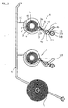
- FIG. 5 illustrates a modified embodiment with a multiple roll holder 101, which can be screwed to a wall and two separators 102 carries training according to the invention.
- the Roller support 103 is formed by a housing that has a film outlet slot 103 '. The lower edge of the film outlet slot 103 'guides the film web when pulling off a track section 131 that is in downward motion is made.
- the bracket 116 with support rail 114 and Separator 111 is between two arms 125 in bearings, only one of which Bearing 121 is visible, pivoted about a pivot axis 124, and between the shielded one illustrated in the upper separator 102
- the operating position 3 corresponds analogously.
- the shielding of the cutting edge 113 of the separating member 111 by the housing 103 and as in the embodiment according to FIGS. 1 to 4 is also in the embodiment 5 the rocker formed by parts 111, 114 and 116 by unequal Weight distribution to the pivot axis 124 biased such that the through the web section 131 similar to the embodiment according to FIGS.
- the rocker transferred to the operating position automatically returns to the starting position, in which the separator 111 its shielded non-use position occupies.
- the separator 111 points here in its operating position - Corresponding to that of the separating member 111 and the bracket 116 Guiding the film web 109 when pulling off a web section 131 obliquely downwards and is pivoted counterclockwise in Fig. 5.
- the operation of the device 102 according to FIG. 5 and that according to FIGS. 1 to 4 is basically the same. In both cases, there remains after the separation process easily graspable film end 8 or 108, the length of the distance of the Cutting edge 13 or 113 to the guide rail 26 or to the film outlet slot 103 'is determined in the operating position of the separating element 11 or 111.
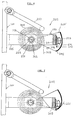
- the separator is accordingly a movable Component forms, is the separator 211 when executing the device 6 and 7 fixed to its support rail 214, which is between extends two support struts 225, which are part of a wall-side attachable Form roll holder 201.
- the supply roll 205 is in execution after 6 and 7 rotatably mounted on a carrier axis as roller carrier 203, the is supported in bearings on the inside of the support struts 225, of which only one bearing 223 is visible.
- the shielding of the cutting edge 213 of the separating member 211 takes over a shielding strip 227, the cutting edge 213 on its outside and on its downward facing front when the device as in Fig. 6 is in the non-use position. Is after subtracting a track section 231 initially towards the bottom of the track section at his pulled free end up, then the film web 209 comes into contact at the lower limit of the shielding strip 227 and takes the side Swivel arms 227 'about a swivel axis 224 that coincides with the axis of rotation for the film roll 205 but can not coincide, pivotally movable Shielding strip 227 with by folding up from its cover position is moved out. As a result, the cutting edge 213 of the separating member 211 exposed, engages with the film web 209 and cuts it along the line of engagement as the web section 231 continues to pull up becomes.
- the shielding strip then works immediately upon completion of the separation process 227 back to its cover position, as shown in Fig. 6, the can be defined by the schematically indicated stop 233.
- a shielding surface 235 at the lower edge of the shielding strip 227 227 can also be provided with a carrier bracket 236, which is between the lower edges of the side pivot arms 227 'of the shield bar 227 extends, as is only indicated schematically in FIG. 6 is.
- a hold-down bracket 237 is provided, which a jumping out of the roll carrier 203 with supply roll 205 the bearings prevented if, for example, violently on the film web 209 at Pulling off a track section 231.
Landscapes
- Life Sciences & Earth Sciences (AREA)
- Forests & Forestry (AREA)
- Engineering & Computer Science (AREA)
- Mechanical Engineering (AREA)
- Replacement Of Web Rolls (AREA)
- Processing And Handling Of Plastics And Other Materials For Molding In General (AREA)
- Winding Of Webs (AREA)
Abstract
Description
- Fig. 1
- eine schaubildliche Darstellung einer ersten Ausführung der Trennvorrichtung nach der Erfindung als Teil eines Rollenhalters für mehrere Vorratsrollen von Folienbahnen,
- Fig. 2
- eine schematische Seitenansicht zu Fig. 1 mit jeweils in abgeschirmter Nichtgebrauchsstellung befindlichem Trennglied der beiden Trennvorrichtungen,
- Fig. 3
- eine Ansicht ähnlich Fig. 1 zur Veranschaulichung der Stellung der Teile unmittelbar vor Beginn des Trennvorganges,
- Fig. 4
- eine Frontansicht zu Fig. 1,
- Fig. 5
- eine Darstellung ähnlich Fig. 2 und 3 zur Veranschaulichung einer zweiten Ausführung der Trennvorrichtung mit einmal in Nichtgebrauchsstellung und einmal in Betriebsstellung dargestelltem Trennglied,
- Fig. 6
- eine Darstellung ähnlich Fig. 5 einer dritten Ausführung der Trennvorrichtung nach der Erfindung mit in Abschirmstellung befindlicher Abschirmleiste, und
- Fig. 7
- die Vorrichtung nach Fig. 6 unmittelbar vor Beginn des Trennvorganges.
Claims (28)
- Vorrichtung zum Abtrennen eines Bahnabschnitts (31;131;231) von dem Ende einer als Vorratsrolle (5;105;205) aufgewickelten Haushaltsfolienbahn (9;109;209), mit einem Rollenträger (3;103;203) für eine drehbare Abstützung der Vorratsrolle (5;105;205) und einem Trennglied (11;111;211), das eine zumindest im wesentlichen parallel zur Drehachse der Vorratsrolle (5;105;205) ausgerichtete, gezahnte Schneide (13;113;213) aufweist, die im Abstand zum Umfang einer auf dem Rollenträger (3;103;203) abgestützten Vorratsrolle (5;105;205) angeordnet ist und in Druckeingriff mit der Folienbahn (9;109;209) diese in voller Breite durchtrennt, gekennzeichnet durch eine Abschirmung der Schneide (13;113;213) des Trenngliedes (11;111;211) bei Nichtgebrauch der Vorrichtung, die betätigt durch einen von der Vorratsrolle abgezogenen Bahnabschnitt (31;131;231) unmittelbar vor und bei dessen Abtrennung aufhebbar ist.
- Vorrichtung nach Anspruch 1, dadurch gekennzeichnet , daß das Trennglied (11) um eine zur Drehachse der Vorratsrolle (5) zumindest im wesentlichen parallele Schwenkachse (24) klappbar abgestützt und durch einen von der Vorratsrolle (5) abgezogenen Bahnabschnitt betätigbaren Bügel (16) aus einer abgeschirmten Nichtgebrauchsstellung in eine Betriebsstellung mit exponierter Schneide (13) bewegbar ist, in der diese bei fortgesetztem Abziehen des am Bügel (16) anliegenden Bahnabschnitts ein Durchtrennen der Folienbahn (9) an der Eingriffslinie der Schneide (13) herbeiführt.
- Vorrichtung nach Anspruch 2, dadurch gekennzeichnet , daß der Mittelschenkel (17) des Bügels (16) parallel zur Schwenkachse (24) des Trennglieds (11) ausgerichtet ist.
- Vorrichtung nach Anspruch 2 oder 3, dadurch gekennzeichnet , daß der Mittelschenkel (17) des Bügels (16) eine Länge aufweist, die annähernd der Breite einer Folienbahn (9) entspricht.
- Vorrichtung nach einem der Ansprüche 2 bis 4, dadurch gekennzeichnet , daß der Bügel (16) eine U-förmige Grundform aufweist und an den freien, abgebogenen Seitenschenkeln (18, 19) mit einer Trägerschiene (14) für das Trennglied (11) verbunden ist.
- Vorrichtung nach Anspruch 5, dadurch gekennzeichnet , daß der Bügel (16) an der Außenseite der Seitenschenkel (18, 19) die Schwenkachse (24) definierende Achszapfen (20, 21) trägt.
- Vorrichtung nach einem der Ansprüche 2 bis 6, dadurch gekennzeichnet , daß die Baueinheit aus Bügel (16) mit Trägerschiene (14) und Trennglied (11) eine Wippe bildet, die durch ungleiche Gewichtsverteilung zur Schwenkachse (24) für eine Bewegung in eine Ausgangsstellung vorbelastet ist, in der das Trennglied (11) seine Nichtgebrauchsstellung einnimmt.
- Vorrichtung nach einem der Ansprüche 2 bis 7, dadurch gekennzeichnet , daß das Trennglied (11) von einer dünnen Edelstahlklinge gebildet ist, die entlang einem Längsrand mit einander benachbarten, gemeinsam die Schneide (13) bildenden Schneidzähnen (12) versehen ist.
- Vorrichtung nach einem der Ansprüche 2 bis 8, dadurch gekennzeichnet , daß der Schneidenbereich (15) des Trennglieds (11) ein- oder beidseitig angeschliffen ist.
- Vorrichtung nach einem der Ansprüche 2 bis 9, dadurch gekennzeichnet , daß in der Nichtgebrauchsstellung das Trennglied (11) an einer Anschlagleiste (27) anliegt, die die Schneide (13) des Trennglieds (11) an einer Breitseite und an der Frontseite abdeckt.
- Vorrichtung nach einem der Ansprüche 7 bis 10, dadurch gekennzeichnet , daß das Trennglied (11) zumindest mit voller Schneidentiefe über die Trägerschiene (14) vorsteht.
- Vorrichtung nach einem der Ansprüche 2 bis 11, dadurch gekennzeichnet , daß der Bügel (16) in der Betriebsstellung für das Trennglied (11) an einem Anschlag (28) anliegt.
- Vorrichtung nach einem der Ansprüche 2 bis 12, dadurch gekennzeichnet , daß das Trennglied (11) in seiner Betriebsstellung eine Ausrichtung zu einem abzutrennenden, am Bügel (16) anliegenden und unter Zugspannung gehaltenen Bahnabschnitt (31) aufweist, bei der der Schneidenbereich (15) mit dem zum Bügel (16) führenden Teil des Bahnabschnitts (31) einen spitzen Anstellwinkel (30) einschließt.
- Vorrichtung nach Anspruch 13, dadurch gekennzeichnet , daß der Anstellwinkel (30) zwischen 45° und 75°, vorzugsweise 60°, beträgt.
- Vorrichtung nach einem oder mehreren der Ansprüche 2 bis 14, dadurch gekennzeichnet , daß der auf dem Rollenträger (3) abgestützten Vorratsrolle (5) eine zur Drehachse der Vorratsrolle (5) zumindest im wesentlichen parallele Führungsschiene (26) nachgeordnet ist.
- Vorrichtung nach Anspruch 15, dadurch gekennzeichnet , daß die Führungsschiene (26) in ihrem Eingriffsbereich mit einem abzuziehenden Bahnabschnitt eine das Übergleiten der Folie begünstigende Beschichtung aufweist.
- Vorrichtung nach Anspruch 15, dadurch gekennzeichnet , daß die Führungsschiene (26) in ihrem Eingriffsbereich mit einem abzuziehenden Bahnabschnitt eine das Übergleiten der Folie begünstigende Gleitrolle aufweist.
- Vorrichtung nach einem der Ansprüche 15 bis 17, dadurch gekennzeichnet , daß die Führungsschiene (26) zugleich die Anschlagleiste für das Trennglied in dessen Nichtgebrauchsstellung bildet.
- Vorrichtung nach einem der Ansprüche 15 bis 18, dadurch gekennzeichnet , daß die Schneide des Trenngliedes in dessen Nichtgebrauchsstellung auf einer Seite einer gedachten, an die Folieneingriffsflächen von Führungsschiene (26) und Bügel (16) tangential angelegten Verbindungsebene gelegen ist und in der Betriebsstellung des Trennglieds (11) eine Lage auf der anderen Seite der Verbindungsebene (29) und mit größerem Abstand zu dieser als in der Nichtgebrauchsstellung einnimmt.
- Vorrichtung nach einem der Ansprüche 2 bis 19, dadurch gekennzeichnet , daß die Ebenen des Bügels (16) und des Trennglieds (11) unter einem Winkel von etwa 90° ausgerichtet sind.
- Vorrichtung nach einem oder mehreren der Ansprüche 1 bis 20, dadurch gekennzeichnet , daß die Folienbahn (9) beim Abziehen eines Bahnabschnitts (31) das Trennglied (11) und den Bügel (16) übergreift.
- Vorrichtung nach einem der Ansprüche 1 bis 21, dadurch gekennzeichnet , daß die Folienbahn (9) beim Abziehen eines Bahnabschnitts (31) das Trennglied (11) und den Bügel (16) untergreift.
- Vorrichtung nach einem der Ansprüche 1 bis 22, dadurch gekennzeichnet , daß der Rollenträger (3) eine oberseitig offene Mulde (4) bildet und eine die Wickelhülse (6) einer Vorratsrolle (5) durchgreifende Achsstange (7) umfaßt, die an ihren Enden radial über den Umfang der Vorratsrolle (5) überstehende Endscheiben (10) als axiale Lagesicherung trägt.
- Vorrichtung nach einem oder mehreren der Ansprüche 2 bis 23, dadurch gekennzeichnet , daß der Rollenträger (103) ein Gehäuse mit einem Folienauslaßschlitz (103') bildet, dessen einer Rand die Folienbahn (109) bei Abzug eines Bahnabschnitts (131) führt, und der Bügel (116) mit Trennglied (111) an Auslegern (125) des Gehäuses (103) im Bereich vor dessen Folienauslaßschlitz (103') gelagert ist.
- Vorrichtung nach Anspruch 1, dadurch gekennzeichnet , daß die Schneide (213) des Trenngliedes (211) zumindest auf einer Breitseite und/oder auf der Frontseite durch eine Abschirmleiste (227) abgedeckt ist, die unmittelbar oder mittelbar durch Heranführen eines von der Vorratsrolle (205) abgezogenen Bahnabschnitts (231) an die Schneide (213) des Trenngliedes (211) aus ihrer Abschirmstellung in eine die Schneide (213) exponierende Freigabestellung bewegbar ist.
- Vorrichtung nach Anspruch 25, dadurch gekennzeichnet , daß die Abschirmleiste (227) klappbar abgestützt ist und eine für den Eingriff mit dem Bahnabschnitt (231) vorgesehene Anlagefläche (227'') aufweist.
- Vorrichtung nach Anspruch 26, dadurch gekennzeichnet , daß die Abschirmleiste (227) mit einem Mitnehmerstab (236) als Übertragungsglied für die Zugkraft des Bahnabschnitts (213) bei der Verlagerung in die Freigabestellung versehen ist.
- Vorrichtung nach einem der Ansprüche 25 bis 28, dadurch gekennzeichnet , daß die Abschirmleiste (227) unter Schwerkraft in ihre Abdeckstellung übergeht.
Applications Claiming Priority (2)
| Application Number | Priority Date | Filing Date | Title |
|---|---|---|---|
| DE29612436U DE29612436U1 (de) | 1996-07-17 | 1996-07-17 | Trennvorrichtung für Folienbahnen |
| DE29612436U | 1996-07-17 |
Publications (3)
| Publication Number | Publication Date |
|---|---|
| EP0819640A2 true EP0819640A2 (de) | 1998-01-21 |
| EP0819640A3 EP0819640A3 (de) | 1999-11-24 |
| EP0819640B1 EP0819640B1 (de) | 2003-02-19 |
Family
ID=8026618
Family Applications (1)
| Application Number | Title | Priority Date | Filing Date |
|---|---|---|---|
| EP97111919A Expired - Lifetime EP0819640B1 (de) | 1996-07-17 | 1997-07-14 | Trennvorrichtung für Folienbahnen |
Country Status (3)
| Country | Link |
|---|---|
| EP (1) | EP0819640B1 (de) |
| AT (1) | ATE232833T1 (de) |
| DE (2) | DE29612436U1 (de) |
Cited By (2)
| Publication number | Priority date | Publication date | Assignee | Title |
|---|---|---|---|---|
| EP1026113A3 (de) * | 1999-02-05 | 2002-04-10 | Rösle Metallwarenfabrik GmbH & Co. KG | Folienspendeeinrichtung |
| EP1792863A3 (de) * | 2005-11-30 | 2007-08-01 | Leifheit Ag | Trennvorrichtung für Folienbahnen |
Family Cites Families (11)
| Publication number | Priority date | Publication date | Assignee | Title |
|---|---|---|---|---|
| DE254964C (de) * | ||||
| US3131278A (en) * | 1962-02-16 | 1964-04-28 | Rosenthal Harry | Dispensing apparatus |
| DE1935526U (de) * | 1966-01-26 | 1966-03-31 | Theodor Kissmann | Schutzvorrichtung. |
| CH616578A5 (en) * | 1977-04-27 | 1980-04-15 | Apura Gmbh | Device for securely clamping a paper strip which is to be unrolled from a roll |
| US4454974A (en) * | 1982-04-16 | 1984-06-19 | Cct Associates | Paper towel regulator and dispenser |
| JPS6392569A (ja) * | 1986-10-02 | 1988-04-23 | Sakae Urushizaki | テ−プカツタ |
| DE8717588U1 (de) * | 1987-02-24 | 1989-03-30 | Apura Gmbh, 6502 Mainz-Kostheim | Vorrichtung zur Ausgabe von Abschnitten eines auf einer Rolle aufgewickelten bahnförmigen Materials |
| US4989769A (en) * | 1989-07-20 | 1991-02-05 | Minnesota Mining And Manufacturing Company | Blade guard |
| DE4034504A1 (de) * | 1990-10-30 | 1992-05-07 | Feldmuehle Gmbh Scott | Vorrichtung zum ausgeben von bahnabschnitten von einer abgaberolle |
| GB2255925A (en) * | 1991-02-06 | 1992-11-25 | Guardline Limited | Foil or film dispenser |
| US5146828A (en) * | 1991-03-29 | 1992-09-15 | Huang Hong Yuan | Wrap film cutter |
-
1996
- 1996-07-17 DE DE29612436U patent/DE29612436U1/de not_active Expired - Lifetime
-
1997
- 1997-07-14 AT AT97111919T patent/ATE232833T1/de active
- 1997-07-14 DE DE59709332T patent/DE59709332D1/de not_active Expired - Lifetime
- 1997-07-14 EP EP97111919A patent/EP0819640B1/de not_active Expired - Lifetime
Cited By (2)
| Publication number | Priority date | Publication date | Assignee | Title |
|---|---|---|---|---|
| EP1026113A3 (de) * | 1999-02-05 | 2002-04-10 | Rösle Metallwarenfabrik GmbH & Co. KG | Folienspendeeinrichtung |
| EP1792863A3 (de) * | 2005-11-30 | 2007-08-01 | Leifheit Ag | Trennvorrichtung für Folienbahnen |
Also Published As
| Publication number | Publication date |
|---|---|
| DE29612436U1 (de) | 1996-09-19 |
| EP0819640B1 (de) | 2003-02-19 |
| DE59709332D1 (de) | 2003-03-27 |
| ATE232833T1 (de) | 2003-03-15 |
| EP0819640A3 (de) | 1999-11-24 |
Similar Documents
| Publication | Publication Date | Title |
|---|---|---|
| DE3690545C2 (de) | Vorrichtung zur abgabe von Bandabschnitten von einer Rolle aus Bandmaterial | |
| DE69924099T2 (de) | Rollenpapierspender mit zentralem Innenabzug | |
| DE2811842C2 (de) | Abdeckmaschine | |
| DE3779925T2 (de) | Spender. | |
| DE3049686T1 (de) | Machine for producing the bodies of conical receptacles | |
| DE2232663A1 (de) | Zusatzeinrichtung an einem spender fuer klebebaender | |
| DE2945949A1 (de) | Rollo | |
| EP0819640B1 (de) | Trennvorrichtung für Folienbahnen | |
| DE3813786A1 (de) | Vorrichtung zum abschneiden eines stranges der tabakverarbeitenden industrie | |
| DE3141811A1 (en) | Holder for a roll of a material web | |
| DE3324628C2 (de) | ||
| EP0011262A1 (de) | Vorrichtung zur Ausgabe von Papierschnitten vorgegebener Länge | |
| DE69301705T2 (de) | Rollenpapierspender | |
| DE19648255C1 (de) | Schneidvorrichtung und Verschließgerät mit einer Schneidvorrichtung | |
| EP0281764B1 (de) | Verfahren und Vorrichtung zur Herstellung von geschlitzten Isolierschläuchen für Rohre oder dergleichen | |
| DE60306688T2 (de) | Vorrichtung zur ausgabe zweiseitiger klebekomponenten eines klebstoffs | |
| DE579425C (de) | Vorrichtung zum Ausstanzen und Ausgeben von Schutzauflagen fuer Klosettsitze | |
| DE952542C (de) | Verfahren und Vorrichtung zum Abtrennen von Belegungs- und/oder Dielektrikumfolien elektrischer Wickelkondensatoren | |
| DE9103605U1 (de) | Folienspender mit Trennvorrichtung | |
| DE19727198C2 (de) | Kleisterauftragsgerät für Tapetenbahnen | |
| DE628328C (de) | Hilfsvorrichtung fuer von der Unterseite eines Bogenstapels arbeitende Bogeneinzugvorrichtungen | |
| DE1965927C3 (de) | Handgerät zum Auftragen von Selbstklebebändern, insbesondere zum Verschließen von Kartons | |
| EP0046153A1 (de) | Toilettenpapierspender für die Aufnahme von mindestens zwei Papierrollen | |
| DE8913685U1 (de) | Trennvorrichtung für Würstchenpaare oder Würstchenreihen | |
| DE232318C (de) |
Legal Events
| Date | Code | Title | Description |
|---|---|---|---|
| PUAI | Public reference made under article 153(3) epc to a published international application that has entered the european phase |
Free format text: ORIGINAL CODE: 0009012 |
|
| AK | Designated contracting states |
Kind code of ref document: A2 Designated state(s): AT BE CH DE FR GB IE LI |
|
| AX | Request for extension of the european patent |
Free format text: AL;LT;LV;RO;SI |
|
| PUAL | Search report despatched |
Free format text: ORIGINAL CODE: 0009013 |
|
| AK | Designated contracting states |
Kind code of ref document: A3 Designated state(s): AT BE CH DE DK ES FI FR GB GR IE IT LI LU MC NL PT SE |
|
| AX | Request for extension of the european patent |
Free format text: AL;LT;LV;RO;SI |
|
| 17P | Request for examination filed |
Effective date: 20000111 |
|
| AKX | Designation fees paid |
Free format text: AT BE CH DE FR GB IE LI |
|
| 17Q | First examination report despatched |
Effective date: 20011107 |
|
| GRAH | Despatch of communication of intention to grant a patent |
Free format text: ORIGINAL CODE: EPIDOS IGRA |
|
| GRAH | Despatch of communication of intention to grant a patent |
Free format text: ORIGINAL CODE: EPIDOS IGRA |
|
| GRAA | (expected) grant |
Free format text: ORIGINAL CODE: 0009210 |
|
| AK | Designated contracting states |
Designated state(s): AT BE CH DE FR GB IE LI |
|
| REG | Reference to a national code |
Ref country code: GB Ref legal event code: FG4D Free format text: NOT ENGLISH |
|
| REG | Reference to a national code |
Ref country code: CH Ref legal event code: EP |
|
| REG | Reference to a national code |
Ref country code: CH Ref legal event code: NV Representative=s name: PATENTANWAELTE FELDMANN & PARTNER AG |
|
| REG | Reference to a national code |
Ref country code: IE Ref legal event code: FG4D Free format text: GERMAN |
|
| REF | Corresponds to: |
Ref document number: 59709332 Country of ref document: DE Date of ref document: 20030327 Kind code of ref document: P |
|
| REG | Reference to a national code |
Ref country code: CH Ref legal event code: PFA Owner name: HEINRICH J. KESSEBOEHMER KG Free format text: HEINRICH J. KESSEBOEHMER DRAHT- UND METALLWARENFABRIK#MINDENER STRASSE 208#49152 BAD ESSEN (DE) -TRANSFER TO- HEINRICH J. KESSEBOEHMER KG#MINDENER STRASSE 208#49152 BAD ESSEN (DE) |
|
| RAP2 | Party data changed (patent owner data changed or rights of a patent transferred) |
Owner name: HEINRICH J. KESSEBOEHMER KG |
|
| GBT | Gb: translation of ep patent filed (gb section 77(6)(a)/1977) | ||
| ET | Fr: translation filed | ||
| PLBQ | Unpublished change to opponent data |
Free format text: ORIGINAL CODE: EPIDOS OPPO |
|
| PLBI | Opposition filed |
Free format text: ORIGINAL CODE: 0009260 |
|
| PLAX | Notice of opposition and request to file observation + time limit sent |
Free format text: ORIGINAL CODE: EPIDOSNOBS2 |
|
| 26 | Opposition filed |
Opponent name: ROESLE METALLWARENFABRIK & CO. KG Effective date: 20031119 |
|
| PLAX | Notice of opposition and request to file observation + time limit sent |
Free format text: ORIGINAL CODE: EPIDOSNOBS2 |
|
| PLAX | Notice of opposition and request to file observation + time limit sent |
Free format text: ORIGINAL CODE: EPIDOSNOBS2 |
|
| PLBB | Reply of patent proprietor to notice(s) of opposition received |
Free format text: ORIGINAL CODE: EPIDOSNOBS3 |
|
| APBP | Date of receipt of notice of appeal recorded |
Free format text: ORIGINAL CODE: EPIDOSNNOA2O |
|
| APAH | Appeal reference modified |
Free format text: ORIGINAL CODE: EPIDOSCREFNO |
|
| APAH | Appeal reference modified |
Free format text: ORIGINAL CODE: EPIDOSCREFNO |
|
| APBQ | Date of receipt of statement of grounds of appeal recorded |
Free format text: ORIGINAL CODE: EPIDOSNNOA3O |
|
| PLAB | Opposition data, opponent's data or that of the opponent's representative modified |
Free format text: ORIGINAL CODE: 0009299OPPO |
|
| REG | Reference to a national code |
Ref country code: CH Ref legal event code: PFA Owner name: HEINRICH J. KESSEBOEHMER KG Free format text: HEINRICH J. KESSEBOEHMER KG#MINDENER STRASSE 208#49152 BAD ESSEN (DE) -TRANSFER TO- HEINRICH J. KESSEBOEHMER KG#MINDENER STRASSE 208#49152 BAD ESSEN (DE) |
|
| APBU | Appeal procedure closed |
Free format text: ORIGINAL CODE: EPIDOSNNOA9O |
|
| PLCK | Communication despatched that opposition was rejected |
Free format text: ORIGINAL CODE: EPIDOSNREJ1 |
|
| PLBN | Opposition rejected |
Free format text: ORIGINAL CODE: 0009273 |
|
| STAA | Information on the status of an ep patent application or granted ep patent |
Free format text: STATUS: OPPOSITION REJECTED |
|
| 27O | Opposition rejected |
Effective date: 20071113 |
|
| REG | Reference to a national code |
Ref country code: DE Ref legal event code: R082 Ref document number: 59709332 Country of ref document: DE Representative=s name: BUSSE & BUSSE PATENT- UND RECHTSANWAELTE PARTN, DE Effective date: 20120516 Ref country code: DE Ref legal event code: R081 Ref document number: 59709332 Country of ref document: DE Owner name: KESSEBOEHMER HOLDING KG, DE Free format text: FORMER OWNER: HEINRICH J. KESSEBOEHMER KG, 49152 BAD ESSEN, DE Effective date: 20120516 Ref country code: DE Ref legal event code: R081 Ref document number: 59709332 Country of ref document: DE Owner name: KESSEBOEHMER HOLDING E.K., DE Free format text: FORMER OWNER: HEINRICH J. KESSEBOEHMER KG, 49152 BAD ESSEN, DE Effective date: 20120516 |
|
| REG | Reference to a national code |
Ref country code: CH Ref legal event code: PFA Owner name: KESSEBOEHMER HOLDING E.K. Free format text: HEINRICH J. KESSEBOEHMER KG#MINDENER STRASSE 208#49152 BAD ESSEN (DE) -TRANSFER TO- KESSEBOEHMER HOLDING E.K.#MINDENER STRASSE 208#49152 BAD ESSEN (DE) |
|
| REG | Reference to a national code |
Ref country code: AT Ref legal event code: HC Ref document number: 232833 Country of ref document: AT Kind code of ref document: T Owner name: KESSEBOEHMER HOLDING E.K., DE Effective date: 20121018 |
|
| REG | Reference to a national code |
Ref country code: DE Ref legal event code: R082 Ref document number: 59709332 Country of ref document: DE Representative=s name: BUSSE & BUSSE PATENT- UND RECHTSANWAELTE PARTN, DE Ref country code: DE Ref legal event code: R081 Ref document number: 59709332 Country of ref document: DE Owner name: KESSEBOEHMER HOLDING KG, DE Free format text: FORMER OWNER: KESSEBOEHMER HOLDING E.K., 49152 BAD ESSEN, DE |
|
| REG | Reference to a national code |
Ref country code: CH Ref legal event code: PFA Owner name: KESSEBOEHMER HOLDING KG, DE Free format text: FORMER OWNER: KESSEBOEHMER HOLDING E.K., DE |
|
| REG | Reference to a national code |
Ref country code: FR Ref legal event code: PLFP Year of fee payment: 20 |
|
| PGFP | Annual fee paid to national office [announced via postgrant information from national office to epo] |
Ref country code: GB Payment date: 20160609 Year of fee payment: 20 Ref country code: IE Payment date: 20160630 Year of fee payment: 20 |
|
| REG | Reference to a national code |
Ref country code: AT Ref legal event code: HC Ref document number: 232833 Country of ref document: AT Kind code of ref document: T Owner name: KESSEBOEHMER HOLDING KG, DE Effective date: 20160802 |
|
| PGFP | Annual fee paid to national office [announced via postgrant information from national office to epo] |
Ref country code: DE Payment date: 20160602 Year of fee payment: 20 |
|
| PGFP | Annual fee paid to national office [announced via postgrant information from national office to epo] |
Ref country code: FR Payment date: 20160728 Year of fee payment: 20 Ref country code: AT Payment date: 20160727 Year of fee payment: 20 |
|
| PGFP | Annual fee paid to national office [announced via postgrant information from national office to epo] |
Ref country code: BE Payment date: 20160628 Year of fee payment: 20 |
|
| PGFP | Annual fee paid to national office [announced via postgrant information from national office to epo] |
Ref country code: CH Payment date: 20161026 Year of fee payment: 20 |
|
| REG | Reference to a national code |
Ref country code: DE Ref legal event code: R071 Ref document number: 59709332 Country of ref document: DE |
|
| REG | Reference to a national code |
Ref country code: CH Ref legal event code: PL |
|
| REG | Reference to a national code |
Ref country code: GB Ref legal event code: PE20 Expiry date: 20170713 |
|
| REG | Reference to a national code |
Ref country code: IE Ref legal event code: MK9A |
|
| REG | Reference to a national code |
Ref country code: AT Ref legal event code: MK07 Ref document number: 232833 Country of ref document: AT Kind code of ref document: T Effective date: 20170714 |
|
| PG25 | Lapsed in a contracting state [announced via postgrant information from national office to epo] |
Ref country code: GB Free format text: LAPSE BECAUSE OF EXPIRATION OF PROTECTION Effective date: 20170713 Ref country code: IE Free format text: LAPSE BECAUSE OF EXPIRATION OF PROTECTION Effective date: 20170714 |