EP0819814A2 - Schloss für den zweiten Flügel von Feuerschutztüren - Google Patents
Schloss für den zweiten Flügel von Feuerschutztüren Download PDFInfo
- Publication number
- EP0819814A2 EP0819814A2 EP97203110A EP97203110A EP0819814A2 EP 0819814 A2 EP0819814 A2 EP 0819814A2 EP 97203110 A EP97203110 A EP 97203110A EP 97203110 A EP97203110 A EP 97203110A EP 0819814 A2 EP0819814 A2 EP 0819814A2
- Authority
- EP
- European Patent Office
- Prior art keywords
- slide
- casing
- activating lever
- rods
- slides
- Prior art date
- Legal status (The legal status is an assumption and is not a legal conclusion. Google has not performed a legal analysis and makes no representation as to the accuracy of the status listed.)
- Withdrawn
Links
Images

Classifications
-
- E—FIXED CONSTRUCTIONS
- E05—LOCKS; KEYS; WINDOW OR DOOR FITTINGS; SAFES
- E05B—LOCKS; ACCESSORIES THEREFOR; HANDCUFFS
- E05B17/00—Accessories in connection with locks
- E05B17/20—Means independent of the locking mechanism for preventing unauthorised opening, e.g. for securing the bolt in the fastening position
- E05B17/2084—Means to prevent forced opening by attack, tampering or jimmying
-
- E—FIXED CONSTRUCTIONS
- E05—LOCKS; KEYS; WINDOW OR DOOR FITTINGS; SAFES
- E05B—LOCKS; ACCESSORIES THEREFOR; HANDCUFFS
- E05B15/00—Other details of locks; Parts for engagement by bolts of fastening devices
- E05B15/004—Lost motion connections
-
- E—FIXED CONSTRUCTIONS
- E05—LOCKS; KEYS; WINDOW OR DOOR FITTINGS; SAFES
- E05B—LOCKS; ACCESSORIES THEREFOR; HANDCUFFS
- E05B5/00—Handles completely let into the surface of the wing
-
- E—FIXED CONSTRUCTIONS
- E05—LOCKS; KEYS; WINDOW OR DOOR FITTINGS; SAFES
- E05C—BOLTS OR FASTENING DEVICES FOR WINGS, SPECIALLY FOR DOORS OR WINDOWS
- E05C7/00—Fastening devices specially adapted for two wings
- E05C7/04—Fastening devices specially adapted for two wings for wings which abut when closed
-
- E—FIXED CONSTRUCTIONS
- E05—LOCKS; KEYS; WINDOW OR DOOR FITTINGS; SAFES
- E05C—BOLTS OR FASTENING DEVICES FOR WINGS, SPECIALLY FOR DOORS OR WINDOWS
- E05C9/00—Arrangements of simultaneously actuated bolts or other securing devices at well-separated positions on the same wing
- E05C9/04—Arrangements of simultaneously actuated bolts or other securing devices at well-separated positions on the same wing with two sliding bars moved in opposite directions when fastening or unfastening
-
- E—FIXED CONSTRUCTIONS
- E05—LOCKS; KEYS; WINDOW OR DOOR FITTINGS; SAFES
- E05B—LOCKS; ACCESSORIES THEREFOR; HANDCUFFS
- E05B65/00—Locks or fastenings for special use
- E05B65/10—Locks or fastenings for special use for panic or emergency doors
-
- E—FIXED CONSTRUCTIONS
- E05—LOCKS; KEYS; WINDOW OR DOOR FITTINGS; SAFES
- E05B—LOCKS; ACCESSORIES THEREFOR; HANDCUFFS
- E05B65/00—Locks or fastenings for special use
- E05B65/10—Locks or fastenings for special use for panic or emergency doors
- E05B65/1006—Locks or fastenings for special use for panic or emergency doors of the vertical rod type
Definitions
- the present invention concerns a lock for the secondary leaf of fire doors.
- the secondary leaf of these fire doors is generally provided with a locking device which normally attaches it to the frame.
- this locking device usually consists of a lock which is provided with a pair of rods which slide vertically, in opposite directions, in the leaf, such that they can engage in ferrules in corresponding seats provided respectively in the door frame and in the floor.
- the said rods enable the door to be opened fully, whereas in the extended position they lock the secondary leaf.
- the rods in question are generally slid into the extended leaf-locking position by means of a mechanism which is actuated manually by a lever or handle.
- the said mechanism is preferably fitted in a seat provided in the profile of the secondary leaf.
- the activating lever is disposed in a housing which is delimited by the mechanism casing.
- the said activating lever usually has a pair of transverse pins by means of which it engages the locking rods, such as to enable them to be moved into the said extended locking position and the retracted release position.
- the leaf is both released and locked manually, by rotating the activating lever angularly, for example by an angle of 180°.
- Locks of this type nevertheless have some disadvantages of both a structural and functional nature, which restrict optimum use thereof. In fact these locks generally have relatively high production costs, as well as dimensions which are often large. In addition, manual closing of the leaf constitutes an obvious limitation in the use of fire doors.
- German Utility Model No G 87 01 630.3 in the name of BKS GmbH describes and claims a lock for a secondary leaf of fire doors which comprises a pair of rods which slide vertically, in opposite directions, between an extended locking position and a retracted release position, and which at their ends engage corresponding seats provided respectively in a door frame and in a floor, a first upper and a second lower slide which can be connected to the rods and guided in a sliding manner vertically in a casing of the lock against respective return spring means between a position of reciprocal withdrawal and a position of approach, corresponding respectively to the locking and the release positions of the rods, a rocker return device pivoted centrally on a first pivot in the casing and having at opposite ends pin coupling grooves into which project pins from the slides, for transmission of movement from the first slide to the second slide, a second pivot on the casing on which an activating lever pivots to act on the first slide against second return spring means, such as to give rise to movement of the slides into the position of reciprocal approach.
- the lock according to the BKS Utility model has the disadvantage that it is large in size, and does not protect adequately against attempted break-ins.
- the object of the present invention is to solve the aforementioned problem, by devising a small lock for the secondary leaf of fire doors, which enables the door to be closed automatically, and which also provides adequate protection against any attempted break-ins.
- a further object of the present invention is to provide a lock for the secondary leaf of fire doors which has a simple design, functions securely and reliably, is versatile, and costs relatively little.
- the present invention provides a lock for a secondary leaf of fire doors comprising a pair of rods which slide vertically, in opposite directions, between an extended locking position and a retracted release position, and which at their ends engage corresponding seats provided respectively in a door frame and in a floor, a first upper and a second lower slide which can be connected to the rods and guided in a sliding manner vertically in a casing of the lock against respective return spring means between a position of reciprocal withdrawal and a position of approach, corresponding respectively to the locking and the release positions of the rods, a rocker return device pivoted centrally on a first pivot in the casing and having at opposite ends pin coupling grooves into which project pins from the slides, for transmission of movement from the first slide to the second slide, a second pivot on the casing on which an activating lever pivots to act on the first slide against second return spring means, such as to give rise to movement of the slides into the position of reciprocal approach, characterised in that the activating lever is located within the casing and the front face of
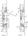
- reference numeral 1 indicates the casing of the lock in question, which is destined to be fitted in a seat provided in the secondary leaf of a fire door.
- the casing 1 has a front 2 of a shape which is extended vertically, in which there is provided an aperture 3 for extraction of a lever 4 for activation of the lock.
- the activating lever 4 is hinged at the top of the casing 1 on a transverse fulcrum 5, and has a lower folded portion 6 which enables it to be gripped.
- the lever 4 is stressed by a flexure spring 7, which is disposed at the fulcrum 5, and which acts against rotation of the lever in the opening position.
- first and second, respectively upper and lower slides 8, 9 which are connected to the casing by means of respective springs 10 which fulfil a return function along the axis of sliding of the slides; for the sake of greater clarity, in the drawing only the spring 10 relative to the upper slide 8 is shown.
- the spring 10 relative to the slide 8 is located between a projection 20 extending perpendicularly from the slide 8 itself and an abutment surface 21.
- the slides 8, 9 are advantageously made of flattened metal elements which are disposed such as to be coplanar on the vertical sliding plane. On the side facing longitudinally outwards, the slides 8, 9 have a slot 11 which is destined to be coupled with a coupling device of the respective leaf closing rods, not shown in the drawing.
- the slides 8, 9 slide longitudinally in opposite directions between a reciprocal withdrawal position and an approach position, which correspond respectively to the extended locking position and the retracted release position of the rods.
- On the top of the upper locking rod there is preferably associated a locking mechanism which can maintain the rod in the retracted position when the leaf is open, and which is preferably of the type illustrated in European Patent No 0, 547,746.
- the slides 8, 9 are articulated to one another on the side facing the inside of the casing 1, by means of a rocker return device 12, which is hinged to a fulcrum 13 transverse to the casing.
- a rocker return device 12 On opposite longitudinal ends the rocker 12 has grooves 14 destined for sliding coupling with respective pins 15 which project transversely from the slides 8, 9.
- the pins 15 are guided along respective slots 16 which are provided vertically in the casing 1.
- the activating lever 4 On its top, the activating lever 4 has a tooth 18 with a suitably rounded profile, which during the opening stage can abut a roller pin 19 which projects transversely from the upper slide 8.
- the slide 8 is provided with an extended opening or
- the pin may serve to locate the abutment surface, as in the disclosed embodiment.
- the slides 8, 9 are disposed in a position of maximum reciprocal withdrawal, corresponding to the extended position of the locking rods of the leaf ( Figure 1); the slides 8, 9 are stressed by the respective springs 10 which act longitudinally in opposite directions, and such as to draw the slides outwards.
- the activating lever 4 is rotated angularly, such that by means of the tooth 18 it acts on the roller pin 19 of the upper slide 8. It should be noted that the lever 4 travels a limited unloaded path before engaging the pin 19 ( Figure 3). This enables the lever 4 to be extracted partially from its seat without force, by means of the gripper portion 6, and thus allows the opening mechanism to be activated more easily.
- the locking mechanism which is associated with the upper locking rod maintains the rods in the retracted, release position, until the leaf is reclosed.
- the activating lever 4 is returned elastically inside its seat, by the spring 7.
- the above-described locking device automatically releases the upper locking rod, enabling the slides 8, 9 to return to the withdrawn position of extraction of the locking rods, by means of the thrust exerted by the springs 10.
- the leaf is opened manually by means of the activating lever 4, whereas closing takes place automatically, with an obvious functional advantage.
- the locking mechanism described has very small dimensions, in particular on the transverse plane, such that the possibility of fitting it in the door leaf is optimised. This is obtained in particular by production of the slides 8, 9 using flattened coplanar elements.
- the activating lever 4 and the rocker 12 in turn contribute to this reduction of size, since they are also made of flattened elements which are disposed on a vertical plane abutting that of the slides 8, 9.
- the lock provides improved protection against any attempted break-ins, since the lower slide 9 can slide upwards independently of the upper slide 8. In fact if an attempt is made to release the closing mechanism from the bottom by means of the lower closing rod, only the slide 9 slides, which, owing to the flattened portion 17, does not make the rocker 12 pivot. Thus the upper slide 8 is not moved, and the corresponding closing rod ensures that the leaf remains locked.
- the above-described possibility of independent sliding of the lower slide 9 is also advantageous in normal use of the door, in order to compensate for partial obstruction of the engagement seat of the lower closing rod ferrule, caused for example by the presence of dirt or the like.
- the upper slide 8 can complete the full raising course of the corresponding closing rod, for engagement of the ferrule of this rod in the seat provided on the door jamb, whereas the lower slide 9 can remain partially raised, without causing stress on the lock mechanism.
Landscapes
- Engineering & Computer Science (AREA)
- Mechanical Engineering (AREA)
- Special Wing (AREA)
- Power-Operated Mechanisms For Wings (AREA)
- Specific Sealing Or Ventilating Devices For Doors And Windows (AREA)
Applications Claiming Priority (3)
| Application Number | Priority Date | Filing Date | Title |
|---|---|---|---|
| ITMI930818U | 1993-10-25 | ||
| IT93MI000818U IT230668Y1 (it) | 1993-10-25 | 1993-10-25 | Serratura per l'anta secondaria di porte tagliafuoco |
| EP94307575A EP0649958B2 (de) | 1993-10-25 | 1994-10-14 | Schloss für den Standflügel von Brandschutztüren |
Related Parent Applications (1)
| Application Number | Title | Priority Date | Filing Date |
|---|---|---|---|
| EP94307575A Division EP0649958B2 (de) | 1993-10-25 | 1994-10-14 | Schloss für den Standflügel von Brandschutztüren |
Publications (2)
| Publication Number | Publication Date |
|---|---|
| EP0819814A2 true EP0819814A2 (de) | 1998-01-21 |
| EP0819814A3 EP0819814A3 (de) | 1998-02-25 |
Family
ID=11365887
Family Applications (2)
| Application Number | Title | Priority Date | Filing Date |
|---|---|---|---|
| EP94307575A Expired - Lifetime EP0649958B2 (de) | 1993-10-25 | 1994-10-14 | Schloss für den Standflügel von Brandschutztüren |
| EP97203110A Withdrawn EP0819814A3 (de) | 1993-10-25 | 1994-10-14 | Schloss für den zweiten Flügel von Feuerschutztüren |
Family Applications Before (1)
| Application Number | Title | Priority Date | Filing Date |
|---|---|---|---|
| EP94307575A Expired - Lifetime EP0649958B2 (de) | 1993-10-25 | 1994-10-14 | Schloss für den Standflügel von Brandschutztüren |
Country Status (5)
| Country | Link |
|---|---|
| EP (2) | EP0649958B2 (de) |
| AT (1) | ATE164200T1 (de) |
| DE (1) | DE69409057T2 (de) |
| ES (1) | ES2113619T3 (de) |
| IT (1) | IT230668Y1 (de) |
Families Citing this family (3)
| Publication number | Priority date | Publication date | Assignee | Title |
|---|---|---|---|---|
| DE202006014041U1 (de) * | 2006-09-13 | 2006-11-23 | Emka Beschlagteile Gmbh & Co. Kg | Klapp-Hebelverschluss |
| DE102013000968A1 (de) * | 2013-01-22 | 2014-07-24 | Assa Abloy Sicherheitstechnik Gmbh | Schlosseinrichtung mit Riegelstangen-Betätigungshandhabe |
| CN119981558B (zh) * | 2025-03-18 | 2025-10-17 | 浙江金大门业有限公司 | 一种插销机构及双扇门 |
Citations (1)
| Publication number | Priority date | Publication date | Assignee | Title |
|---|---|---|---|---|
| DE2546549A1 (de) * | 1975-10-17 | 1977-04-21 | Karrenberg Fa Wilhelm | Panikschloss mit falle und riegel |
Family Cites Families (10)
| Publication number | Priority date | Publication date | Assignee | Title |
|---|---|---|---|---|
| DE12912C (de) * | C. D. CH. brühs und H. pollack in Hamburg | Selbstschliefsender Kantenriegel für zweiflügelige Thüren | ||
| FR2252016A5 (de) * | 1973-11-15 | 1975-06-13 | Chauvat & Sofranq Reunis | |
| US4488378A (en) * | 1983-02-28 | 1984-12-18 | Kawneer Company, Inc. | Building entrance |
| DE3417054A1 (de) * | 1984-05-09 | 1985-11-14 | BKS GmbH, 5620 Velbert | Treibstangenverschluss fuer den standfluegel von zweifluegeligen tueren, insbesondere selbsttaetig schliessenden feuerschutztueren |
| US4663949A (en) * | 1985-04-02 | 1987-05-12 | Barry Yane | Door latch assembly |
| DE8701630U1 (de) * | 1987-02-04 | 1987-05-14 | BKS GmbH, 5620 Velbert | Treibstangenverschluß für den Standflügel von zweiflügeligen Türen |
| FR2650022B1 (fr) * | 1989-07-24 | 1991-10-25 | Vachette Sa | Boitier median de serrure antipanique multipoint, et serrure antipanique equipee d'un tel boitier |
| US5092144A (en) * | 1990-06-27 | 1992-03-03 | W&F Manufacturing, Inc. | Door handle and lock assembly for sliding doors |
| US5161837A (en) * | 1991-07-23 | 1992-11-10 | Thomas Industries Inc., Builders Brass Works Div. | Rod and case assembly and panic exit device |
| IT1252294B (it) * | 1991-11-15 | 1995-06-08 | Corbin Co | Dispositivo per il bloccaggio dell'asta di chiusura di porte di sicurezza |
-
1993
- 1993-10-25 IT IT93MI000818U patent/IT230668Y1/it active IP Right Grant
-
1994
- 1994-10-14 ES ES94307575T patent/ES2113619T3/es not_active Expired - Lifetime
- 1994-10-14 DE DE69409057T patent/DE69409057T2/de not_active Expired - Fee Related
- 1994-10-14 AT AT94307575T patent/ATE164200T1/de not_active IP Right Cessation
- 1994-10-14 EP EP94307575A patent/EP0649958B2/de not_active Expired - Lifetime
- 1994-10-14 EP EP97203110A patent/EP0819814A3/de not_active Withdrawn
Patent Citations (1)
| Publication number | Priority date | Publication date | Assignee | Title |
|---|---|---|---|---|
| DE2546549A1 (de) * | 1975-10-17 | 1977-04-21 | Karrenberg Fa Wilhelm | Panikschloss mit falle und riegel |
Also Published As
| Publication number | Publication date |
|---|---|
| EP0819814A3 (de) | 1998-02-25 |
| IT230668Y1 (it) | 1999-06-09 |
| EP0649958A3 (de) | 1995-09-20 |
| EP0649958B1 (de) | 1998-03-18 |
| ITMI930818U1 (it) | 1995-04-25 |
| DE69409057D1 (de) | 1998-04-23 |
| EP0649958B2 (de) | 2006-01-11 |
| ITMI930818V0 (it) | 1993-10-25 |
| ES2113619T3 (es) | 1998-05-01 |
| ATE164200T1 (de) | 1998-04-15 |
| DE69409057T2 (de) | 1998-07-02 |
| EP0649958A2 (de) | 1995-04-26 |
Similar Documents
| Publication | Publication Date | Title |
|---|---|---|
| US6266981B1 (en) | Lock, in particular mortise lock for an exterior door | |
| US3433518A (en) | Latch assembly | |
| US6174004B1 (en) | Mortise latch and exit device with concealed vertical rods | |
| US7946080B2 (en) | Lock assembly | |
| US6120071A (en) | Mortise latch vertical rod exit device | |
| US20080078216A1 (en) | Multipoint door lock system with header and sill lock pins | |
| GB2317640A (en) | Door chain security devices | |
| US8556306B1 (en) | Anti-pick latch assembly | |
| EP0644308A1 (de) | Verschluss für Schiebetür | |
| GB2270343A (en) | Multi point door lock | |
| EP0649958B1 (de) | Schloss für den zweiten Flügel von Feuerschutztüren | |
| EP1422368A1 (de) | Schloss | |
| US5080409A (en) | Garage door lock actuation mechanism | |
| DE8704036U1 (de) | Türschloß mit Verriegelungselement und Hilfsfalle | |
| EP3702557A1 (de) | Gegenschloss für einen inaktiven flügel einer doppeltür | |
| GB2391248A (en) | Folding door which can allow both parts to pivot about the main axis | |
| SE467980B (sv) | Laassystem foer bilar | |
| EP4471242A1 (de) | Scharnierverriegelungsmechanismus | |
| EP3702558A1 (de) | Gegenschloss für einen inaktiven flügel einer doppelflügeltür | |
| GB2379952A (en) | Automatic catch for a door or window | |
| AU659035B2 (en) | A lock | |
| EP1715121A2 (de) | Verriegelungsvorrichtung | |
| US833267A (en) | Latch mechanism with automatic detent. | |
| JP2023183957A (ja) | 開き窓の開口制限ストッパー装置 | |
| GB2097461A (en) | Escape door latch |
Legal Events
| Date | Code | Title | Description |
|---|---|---|---|
| PUAI | Public reference made under article 153(3) epc to a published international application that has entered the european phase |
Free format text: ORIGINAL CODE: 0009012 |
|
| PUAL | Search report despatched |
Free format text: ORIGINAL CODE: 0009013 |
|
| AC | Divisional application: reference to earlier application |
Ref document number: 649958 Country of ref document: EP |
|
| AK | Designated contracting states |
Kind code of ref document: A2 Designated state(s): AT BE DE ES FR GB IT LU NL |
|
| AK | Designated contracting states |
Kind code of ref document: A3 Designated state(s): AT BE DE ES FR GB IT LU NL |
|
| 17P | Request for examination filed |
Effective date: 19980319 |
|
| 17Q | First examination report despatched |
Effective date: 20010330 |
|
| RAP1 | Party data changed (applicant data changed or rights of an application transferred) |
Owner name: CORBIN S.R.L. |
|
| GRAP | Despatch of communication of intention to grant a patent |
Free format text: ORIGINAL CODE: EPIDOSNIGR1 |
|
| STAA | Information on the status of an ep patent application or granted ep patent |
Free format text: STATUS: THE APPLICATION IS DEEMED TO BE WITHDRAWN |
|
| 18D | Application deemed to be withdrawn |
Effective date: 20041025 |